Neuropex ENT001 User manual
0120
REF ENT001 / WL-2103A
NEUROPEX


TABLE OF CONTENTS
INTRODUCTION TO TENS
INDICATIONS AND
CONTRAINDICATIONS WARNINGS
PRECAUTIONS/ADVERSE REACTIONS
ABOUT THIS DEVICE
UNIT CONTROLS
ATTACHING THE LEAD WIRES
ELECTRODE SELECTION AND CARE TIPS
FOR SKIN CARE
CONNECTING THE TENS DEVICE
BATTERY INFORMATION
CARING FOR YOUR TENS DEVICE
TROUBLESHOOTING
SYSTEM COMPONENTS
TECHNICAL SPECIFICATIONS
OUTPUT SPECIFICATIONS
WARRANTY
ELECTROMAGNETIC COMPATIBILITY
01
01
02
03
04
04
05
05
06
06
07
08
09
09
10
10
11
12


INTRODUCTION TO TENS
What is Pain?
Pain is the body’s warning system. Pain is important because it
signals an unusual condition in the body and alerts us before
additional damage or injury can occur. However, long-lasting,
persistent pain, often called chronic pain, once diagnosed
serves no apparent purpose. TENS is developed to help relieve
some types of chronic and acute pain.
How does TENS work?
TENS is a method of treating pain that is non-invasive and
non-narcotic.
The TENS device sends comfortable impulses through the skin
that stimulate the nerve (or nerves) in the treatment area. In
many cases this stimulation will greatly reduce or eliminate the
pain sensation you feel by masking the original pain message
sent to the brain.
It is also believed that TENS stimulation helps release endorphins
into the blood stream thereby further reducing pain.
TENS devices are clinically proven to be useful in pain management
for many patients. By reading this manual and carefully following
the treatment instructions given to you by your clinician, you
will attain the maximum benefit from your TENS device.
INDICATIONS AND CONTRAINDICATIONS
Read the operation manual before using TENS.
INDICATIONS
Transcutaneous Electrical Nerve Stimulation (TENS) is intended for
pain relief.
01

CONTRAINDICATIONS
-Patients with implanted electronic devices ( for example, a
pacemaker ) or metallic implants should not undertake TENS
treatment without first consulting a physician.
-Any electrode placement that applies current to the carotid
sinus (neck) region.
-Any electrode placement that causes current to flow
transcerebrally. (through the head).
-The use of TENS whenever pain symptoms are undiagnosed,
until etiology is determined.
WARNINGS
-TENS devices must be kept out of reach of children.
-The safety of TENS devices for use during pregnancy or
delivery has not been established.
-TENS is not effective for pain of central origin (headaches).
-If TENS treatment becomes ineffective or unpleasant,
stimulation should be discontinued until re-evaluation by a
physician.
-Avoid adjusting controls while operating machinery or
vehicles.
-Always turn the TENS device OFF before applying or
removing electrodes.
-TENS may interfere with electronic monitoring equipment
(ECG monitors/alarms).
-Electrodes should not be placed over the eyes, in the mouth,
or internally.
-TENS devices have no curative value.
-TENS is a symptomatic treatment and as such suppresses
the sensation if pain which would otherwise serve as a
protective mechanism.
02
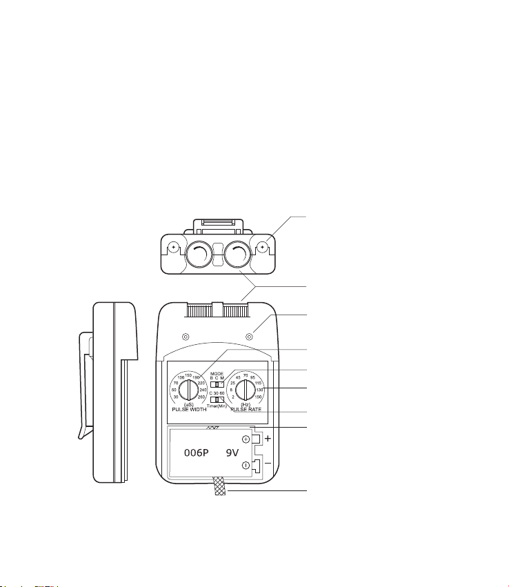
Lead Connector
Intensity Controls
Indicator Light
Pulse Width Control
Mode Selector
Pulse Rate Control
Timer Selector
Battery Compartment
Battery Strip
PRECAUTIONS/ADVERSE REACTIONS
Isolated cases of skin irritations may occur at the site of
electrode placement during long term application.
Effectiveness is highly dependent upon patient selection by a
person qualified in the management of pain patients.
Skin irritation and electrode burns are potential adverse
reactions.
03

ABOUT THIS DEVICE
Your TENS device is a battery operated device that includes two
controllable output channels. This TENS device creates
electrical impulses whose amplitude, duration, and modulation
can be altered with the controls or switches. The TENS dial
controls are very easy to use and the slide cover protects
accidental changes in settings.
UNIT CONTROLS
Panel Cover
A cover conceals the controls for Pulse Width, Pulse Rate, Mode
Selector and Modulation Selector. Press the top side of the
cover and pull down in order to open the cover.
Intensity
The intensity knobs located on the top of the unit affects the
strength of the stimulation and also functions as the ON/OFF
control.
Mode
The Mode switch is used to select the type of treatment utilized.
The three modes are Burst (B), Continuous (C), and Modulation
(M).
Pulse Width
The Pulse Width knob regulates the pulse width for both channels.
Pulse Rate
The Pulse Rate knob regulates the number of pulses per second
for both channels.
Time Control
Treatment Time of TENS can be preset with timer control. This
switch has 3 positions: 30 minutes, 60 minutes and C (continuous).
Push the mode selector until engaged in position desired.
Resetting the Timer
To resume operation or to reset the timer, simply turn the
intensity control OFF and then ON again.
04

Mode Functions
Burst (B) releases individual bursts twice per second. Pulse
width is adjustable and the pulse rate is set at 100Hz per
second.
Continuous (C) stimulation is delivered continuously at the
settings determined by intensity, rate, and width knobs.
Modulation (M) pulse width decreases from its setting by 60%
and maintains the decreased width for 2 seconds before return-
ing to the original width setting, which is maintained for 3.5
seconds. The cycle is then repeated. The intensity and pulse
rate are adjustable.
ATTACHING THE LEAD WIRES
The lead wires provided with the TENS device insert into the
jack sockets located on top of the unit. Holding the insulated
portion of the connector, push the plug end of the wire into one
of the jacks; one or two sets of the wires may be used. After
connecting the wires to the stimulator, attach each wire to an
electrode.
NOTE: Use care when you plug and unplug the wires. Pulling on
the lead wire instead of its insulated connector may cause wire
breakage.
CAUTION: Never insert the plug of the lead wire into an AC power
supply socket.
ELECTRODE SELECTION AND CARE
Your physician/clinician should decide which type of electrode is
best for your condition.
Follow application procedures outlined in electrode packaging to
maintain stimulation and prevent skin irritation. The electrode
packaging will provide instructions for care, maintenance and
proper storage of your electrodes.
05

TIPS FOR SKIN CARE
Good skin care is important for comfortable use of your TENS
device.
-Always clean the electrode site with mild soap and water
solution, rinse well and blot dry thoroughly prior to any
electrode application.
-Any excess hair should be clipped, not shaved, to ensure
good electrode contact with the skin.
-You may choose to use a skin treatment or preparation that
is recommended by your physician/clinician. Apply, let dry,
and apply electrodes as directed. This will both reduce the
chance of skin irritation and extend the life of your electrodes.
-Avoid excessive stretching of the skin when applying
electrodes. This is best accomplished by applying the
electrode and smoothly pressing it in place from the center
outward.
-When removing electrodes, always remove by pulling in the
direction of hair growth.
-It may be helpful to rub skin lotion on electrode placement
area when not wearing electrodes.
CONNECTING THE TENS DEVICE
1. Prepare the Skin
Prepare the skin as previously discussed and according to
instructions provided with your electrodes. Before attaching
the electrodes, identify the area which your physician/clinician
has recommended for electrode placement.
2. Connect lead wires to the electrodes
Connect the lead wires to the electrodes before applying the
electrodes to the skin.
NOTE: Be sure both intensity controls for Channel 1 and 2 are
turned to the “OFF” position.
06

3. Place electrodes on the skin
Place the electrodes on the skin as recommended by your
physician/clinician.
4. Insert Lead Wire Connector to TENS device
Plug end of lead wire into the channel output receptacle to be
used, pushing plug in as far as it will go.
5. Select Treatment Settings
Check and be sure your unit is still set to the proper settings
recommended by your physician/clinician.
6. Adjusting Channel Intensity Control
Locate the intensity control knob at the top of the unit. Turn
channel 1 or 2 clockwise. The indicator light will light up as
long as the unit is in operation. Slowly turn the channel control
in a clockwise direction until you reach the intensity recom-
mended by your physician/clinician. Repeat for the other
channel if both channels are to be used.
If the stimulation levels are uncomfortable or become uncom-
fortable, reduce the stimulation amplitude to a comfortable
level or cease stimulation and contact your physician if
problems persist.
BATTERY INFORMATION
If your TENS device is equipped with a rechargeable battery
system, it will contain two rechargeable Ni-Cad batteries and a
battery charger. This allows you to charge one battery while
the other one is being used in your unit. To protect the life of
your batteries, it is important to continue using a battery until
the indicator light is no longer lit. Removing the battery and
charging it after only a short usage can actually shorten the life
of the Ni-Cad battery.
When the indicator light located on the front of the unit will no
longer light, the battery has become too weak to power the unit
and it is time to charge the battery. At this point the unit will
shut off until a fresh battery is inserted.
Your unit may also be powered by a 9 volt disposable alkaline
battery. This type of battery cannot be recharged and should
be discarded when the yellow light no longer lights.
07

Changing the Battery
When the indicator light on the front of the unit does not remain
lit once the unit is turned on, the battery should be replaced
with a newly charged battery.
1. Remove the panel cover by pressing the top and sliding
down until it is completely removed from the unit. This will
reveal the battery compartment.
2. Remove the discharged battery from the device.
3. Place new battery in compartment. Note the proper polarity
alignment indicated on the battery and the compartment.
Recharging Batteries
1. Take care to note the proper polarity of the battery. If
positioned properly, it will not be necessary to force the battery.
Caution: The battery may overheat and rupture if it is inserted
backwards.
2. Plug the charger and allow it to remain undisturbed for 8 to
10 hours. Remove battery upon completion.
3. Batteries should always be stored fully charged. After being
stored for 60 days or more, the Ni-Cad batteries may lose some
or most of their charge and should be charged prior to use.
CARING FOR YOUR TENS DEVICE
Your TENS device may be cleaned by wiping gently with a damp
cloth moistened with mild soap and water. Never immerse the
device in water or other liquids.
Wipe lead wires with a damp cloth as above if they become
soiled.
To properly store the TENS device for extended period of time,
remove the battery from the unit. Put the unit and accessories
in the carrying case and store in a cool dry location.
08

TROUBLESHOOTING
SYSTEM COMPONENTS
Your TENS device may include the following components or
accessories:
- TENS unit
- Lead wires
- Electrodes
- Battery
- Carry case
- Operation Manual
If the TENS device does not function properly:
1. Make sure the battery is properly installed or replace battery.
Be sure to observe proper polarity markings when replacing the
battery. If the yellow light on the front of the unit does not stay
lit when the unit is turned on, replace the battery and check
again.
2. If the ON/OFF Indicator Light is flashing and you still feel no
stimulation, check that the lead wires are properly connected and
the electrodes are in place. If the unit appears to be functioning
and no stimulation, the lead wires or electrodes may need to be
replaced.
3. If the battery appears to be charged and the unit is not
functioning, turn both lntensity Control Knobs to the OFF
position(counter clockwise). Then gradually turn the lntensity
Control Knob to the on position.
If there is any other problem, please consult or return the device
to your distributor, Do not try to repair a defective device.
09

TECHNICAL SPECIFICATIONS
Dual, isolated between channels
Continuous, Burst, Modulation
Adjustable 0-80mA peak into 500
ohm load each channel,
constant current
2Hz-150Hz (adjustable)
30uS-260uS (adjustable)
Cont., 30 min., 60 min.
Burst consists 2 burst per sec at 100 Hz
Asymmetrical Bi-Phasic square pulse
0-100 Volt (open current)
9 volt battery (alkaline or nickel-cadium
rechargeable)
95(H) x 65(W) x 23.5 (T) mm
115 grams (battery included)
OUTPUT SPECIFICATIONS
Channel:
Modes of Operations:
Pulse Intensity:
Pulse Rate:
Pulse Width:
Timer:
Burst Mode:
Wave Form:
Voltage:
Power Source:
Dimensions:
Weight:
10
WARRANTY
This TENS device carries a two year warranty from the date of
purchase. The warranty applies to the TENS device and necessary
parts and labour relating thereto. The distributor reserves the right
to replace or repair the unit at their discretion.
The warranty does not apply to damage resulting from failure to
follow the operating instructions, accidents, abuse, alteration or
disassembly by unauthorized individuals.
Batteries and electrodes are consumable products and as such are
not included within the warranty.
11
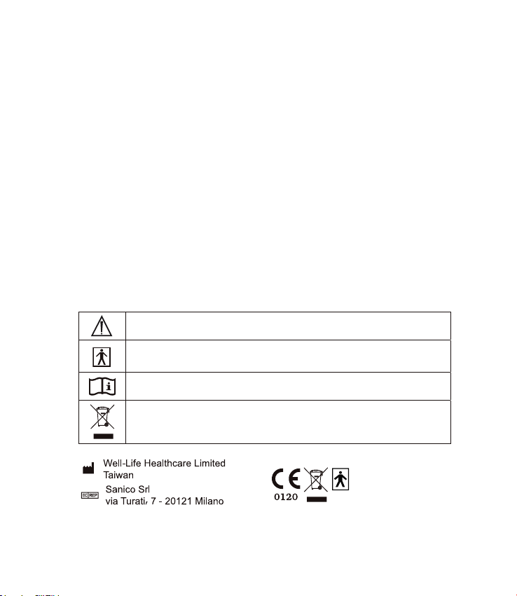
Caution (Output )
TYPE BF equipment
Follow instructions for use
Do not dispose in normal dustbin.
DESCRIPTION OF SYMBOLS:
Well Life model # WL-2103A corresponds to Neuropex Model ENT001
12
Electromagnetic Compatibility
●The device complies with current specifications with regard to
electromagnetic compatibility and is suitable for use in all premises,
including those designated for private residential purposes. The radio
frequency emissions of the device are extremely low and in all probability
do not cause any interference with other devices in the proximity.
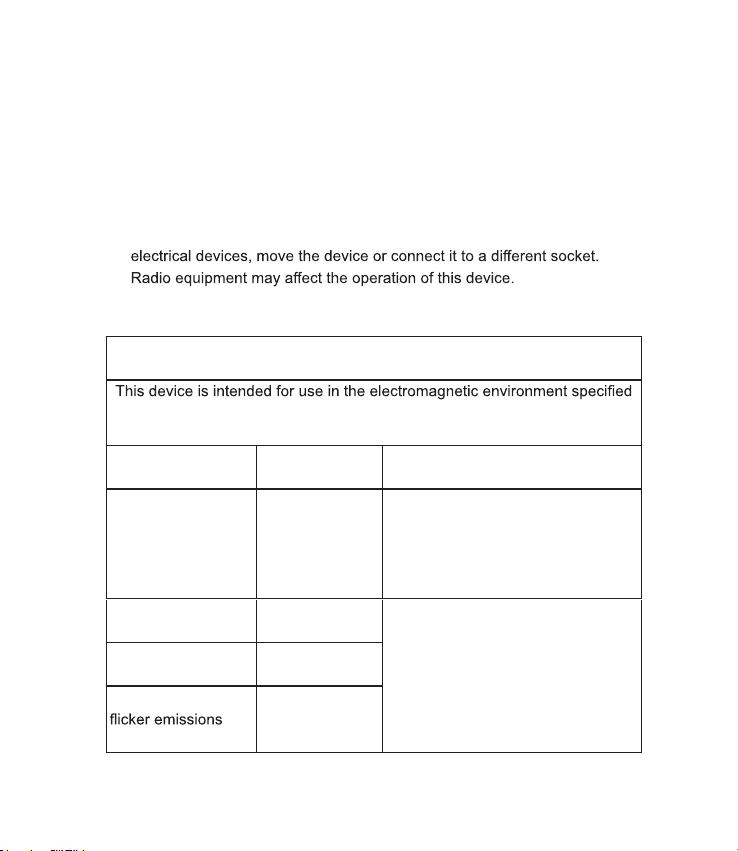
●It is recommended that you do not place the device on top of or close to
other electronic devices. Should you notice any interference with other
●
Electromagnetic Compatibility Information
Guidance and manufacturer’s declaration
– electromagnetic emissions
below. The customer or the user of this device should assure that it is used in
such an environment.
Emissions Compliance Electromagnetic environment
guidance
RF emissions CISPR
11 Group 1
This device uses RF energy only for
its internal function. Therefore, its RF
emissions are very low and are not
likely to cause any interference in
nearby electronic equipment.
RF emissions CISPR
11 Class B This device is suitable for use
in all establishments, including
domestic establishments and those
directly connected to the public low-
voltage power supply network that
supplies buildings used for domestic
purposes.
Harmonic emissions
IEC 61000-3-2 Not Applicable
Voltage fluctuations/
IEC 61000-3-3
Not Applicable

13
Guidance and manufacturer’s declaration
– electromagnetic immunity
below. The customer or the user of this device should assure that it is used in
such an environment.
Immunity
test
IEC 60601
Test level
Compliance
level
Electromagnetic
environment guidance
Electrostatic
discharge
(ESD) IEC
61000-4-2
±6 kV contact
±8 kV air
±6 kV contact
±8 kV air
Floors should be wood, concrete
with synthetic material, the relative
humidity should be at least 30%.
Electrical fast
transient/burst
IEC 61000-4-4
±2 kV for power
supply lines Not applicable
Mains power quality should be that
of a typical commercial or hospital
environment.
Surge
IEC 61000-4-5
±1 kV line(s) and
neutral Not applicable
Mains power quality should be that
of a typical commercial or hospital
environment.
Voltage
dips, short
interruptions
and voltage
variations on
power supply
input lines
IEC 61000-4-11
<5% UT
(>95% dip in UT)
for 0.5 cycle 40%
UT (60% dip in UT)
for 5 cycles 70%
UT (30% dip in UT)
for 25 cycles
<5% UT
Not applicable
Mains power quality should be
that of a typical commercial or
hospital environment. If the user
of this device requires continued
operation during power mains
interruptions, it is recommended
that this device be powered from
an uninterruptible power supply or
a battery.
Power
frequency
(50/60 Hz) 3 A/m 3 A/m
This device power frequency
characteristic of a typical location
in a typical commercial of hospital
environment.
NOTE UT is the a.c. mains voltage prior to application of the test level
14
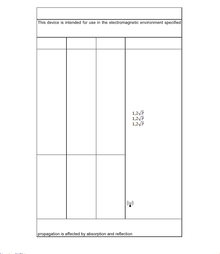
Guidance and manufacturer’s declaration
– electromagnetic immunity
below. The customer or the user of this device should assure that it is used in
such an environment.
Immunity test IEC 60601
Test level
Compliance
level
Electromagnetic
environment guidance
Conducted RF
IEC 61000-4-6
3 Vms
150 kH z to 8 0
MHz
Not applicable
Portable and mobile R F
communic a t ions equipment
should be used no closer to any
part of this device, including
cables, than the recommended
separation distance calculated
from the equation applicable to the
frequency of the transmitter.
Recommended s eparation
distance
d =
d = 80 MHz to 800 MHz
d = 800 MHz to 2.5 GHz
Where P is the maximum output
power rating of the transmitter
in watts (W) according to the
transmitter manufacturer and d
is the recommended separation
Distance in metres (m).
Field strengths from fixed RF
transmitters, as determined by an
electromagnetic site survey should
be less than the compliance level
in each frequency range.
Interference may occur in the
vicinity of equipment marked with
the following symbol:
Radiated RF
IEC 61000-4-3
3 V/m
80 MHz to 2.5
GHz
3 V/m
NOTE 1 At 80 MHz and 800 MHz, the higher frequency range applies.
NOTE 2 These guidelines may not apply in all situations. Electromagnetic
15
a. Field strengths from fixed transmitters, such as base stations for radio
(cellular/cordless) telephones and land mobile radios, amateur radio,
AM and FM radio broadcast and TV broadcast cannot be predicted
theoretically with accuracy. To assess the electromagnetic environment
due to fixed RF transmitters, an electromagnetic site survey should
be considered. If the measured field strength in the location in which
this device is used exceeds the applicable RF compliance level above,
this device should be observed to verify normal operation. If abnormal
performance is observed, additional measures may be necessary, such
as re-orienting or relocating this device.
b.
than 3V/m.
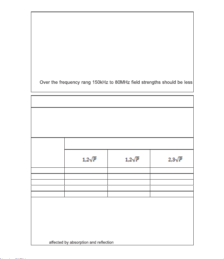
Recommended separation distance b etween portable a nd m obile RF
communications equipment and the device
This device is intended for use in an electromagnetic in which radiated RF disturbances
are controlled. The customer or the user of this device help prevent electromagnetic
interference by maintaining a minimum distance between portable and mobile RF
communications equipment (transmitters) and this device as recommended below,
according to the maximum output power of the communications equipment.
Rated maximum
output power of
transmitter
W
Separation distance according to frequency of transmitter
M
150 kHz to 80 MHz
d =
80 MHz to 800 MHz
d =
800 MHz to 2.5 GHz
d =
0.01 N/A 0.12 0.23
0.1 N/A 0.38 0.73
1 N/A 1.2 2.3
10 N/A 3.8 7.3
100 N/A 12 23
For transmitters rated at a maximum output power not listed above, the recommended
separation distanced in meters (m) can be estimated using the equation applicable to the
frequency of the transmitter, where P is the maximum output power rating of the transmitter
in watts (W) according to the transmitter manufacturer.
NOTE 1: At 80 MHz and 800 MHz, the separation distance for the higher frequency range
applies.
NOTE 2: These guidelines may not apply in all situations. Electromagnetic propagation is

NEUROPEX
IM-21-052 RevA17
WWW.NEUROPEX.CO
This manual suits for next models
1
Table of contents
Popular Medical Equipment manuals by other brands


Getinge
Getinge Arjohuntleigh Nimbus 3 Professional Instructions for use

Mettler Electronics
Mettler Electronics Sonicator 730 Maintenance manual

Pressalit Care
Pressalit Care R1100 Mounting instruction

Denas MS
Denas MS DENAS-T operating manual

bort medical
bort medical ActiveColor quick guide

AccuVein
AccuVein AV400 user manual


