HAWEKA RPV1300 User manual

Operating Instructions
Runout Measurement Device
HAWEKA AG • Kokenhorststraße 4 • D-30938 Burgwedel • Phone +49 5139 8996-0 •
Technical modifications reserved. Text and layout protected. Reprinting and copies, including extracts, are only permitted with written authorisation.
GEB 001 128
Runout measurement device for heavy vehicle tyres


RUNOUT MEASUREMENT DEVICE RPV1300
RPV1300 Operating Instructions
3
Table of Contents
1General Safety Instructions ...............................................................................5
1.1 Operator’s duty of care ................................................................................................5
1.2 Basic safety precautions..............................................................................................6
2Product Description............................................................................................7
2.1 Authorised intended use..............................................................................................8
2.2 Description of the area of application:..........................................................................8
2.3 Technical Data.............................................................................................................9
2.4 PC system requirements for RPV1300 ........................................................................9
3Equipment provided .........................................................................................10
3.1 Parts list for standard version RPV1300 ....................................................................10
4Commissioning.................................................................................................11
4.1 Mounting the laser tripods..........................................................................................11
4.2 Installing the software in Windows.............................................................................12
4.3 Installing the laser driver............................................................................................12
5The RPV1300 Program......................................................................................13
5.1 Setting up the software..............................................................................................13
5.1.1 Customer data:........................................................................................................................14
5.1.2 Language: ...............................................................................................................................14
5.1.3 Interface for laser sensor: .......................................................................................................15
5.1.4 Laser symbol information:.......................................................................................................16
5.1.5 Instructions..............................................................................................................................16
5.1.6 Data directory..........................................................................................................................17
5.1.7 Password ................................................................................................................................17
5.1.8 Saving program settings .........................................................................................................17
5.1.9 Advanced settings...................................................................................................................17
5.1.10 System overview.....................................................................................................................17
6Preparing for measurement recording............................................................18
6.1 Preparatory measures ...............................................................................................18
6.1.1 Setup of measuring device on vehicle wheel..........................................................................19
7Measurement recording ...................................................................................20
7.1 Entering vehicle, wheel and rim data in the program..................................................20
7.2 Selecting the wheel to be measured..........................................................................21
7.3 Assigning the laser sensors.......................................................................................22
7.4 Markings on the wheel...............................................................................................24
7.5 Rotational speed during measurement recording......................................................24
7.6 Start wheel measurement..........................................................................................25
7.7 Error during wheel measurement...............................................................................26
8Control measurement after matching .............................................................27
8.1 Control measurement ................................................................................................27
9Show log............................................................................................................28

RUNOUT MEASUREMENT DEVICE RPV1300
RPV1300 Operating Instructions
4
10 Servicing............................................................................................................30
11 Error description...............................................................................................30
12 Appendix............................................................................................................31
12.1 Measurement log for individual wheel........................................................................31
12.2 Measurement log for overview...................................................................................32
13 EC Declaration of Conformity..........................................................................33
HAWEKA AG
Kokenhorststr. 4 Burgwedel 11.12.17
30938 Burgwedel Release notes page 7
Phone +49 (0)5139 8996 - 0
Fax: +49 (0)5139 8996 222
info@haweka.com
www.haweka.com
RUNOUT MEASUREMENT DEVICE RPV1300
RPV1300 Operating Instructions
5
1 General Safety Instructions
1.1Operator’s duty of care
The runout measurement device RPV1300 has been designed
and built after thorough selection of applicable harmonised
standards. It therefore corresponds to the current state of the art
and offers the highest degree of safety during operation.
The device may only be structurally modified with written
authorisation by the manufacturer!
Device safety can only be implemented during practical operation
if all required applicable measures have been taken. The
operator’s duty of care includes planning such measures and
checking their implementation.
In particular, the operator has to ensure that
•the device is only used for its intended purpose
•the device is only used in a fully functioning state and free
from defects
•the complete operating instructions are permanently
available in a readable condition at the operating location of
the device
•only accordingly qualified and authorised personnel operate
the device
•personnel are regularly instructed in all relevant health and
safety issues and are familiar with the operating instructions,
in particular with the safety instructions contained therein
•all safety and warning notices attached to the machine are
not removed and are legible.
RUNOUT MEASUREMENT DEVICE RPV1300
RPV1300 Operating Instructions
6
1.2Basic safety precautions
The runout measurement device may only be used by accordingly
qualified and authorised personnel who are familiar with these
operating instructions and can work in accordance with these
instructions!
Prior to each use of the device it has to be checked for visible damage
and it must be ensured that the device is only operated when free from
defects! Any defects that are identified must be reported to a superior
immediately!
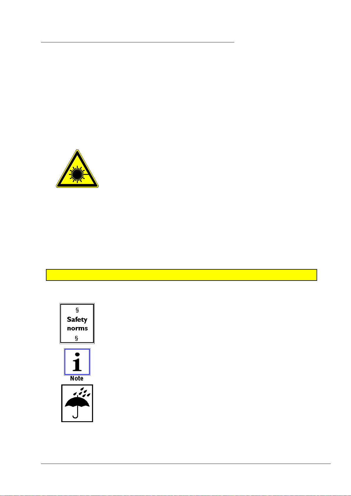
Laser product
CLASS 2
TYPE 1
Warning - laser radiation
This symbol indicates potential danger to persons. (risk of injury)
Some basic instructions must be followed for all lasers:
- Never look directly into the beam!
- Define beam paths precisely!
- Avoid dangerous reflections. Pay particular attention to reflective or
shiny surfaces as these can cause reflections.
- Turn off the laser after work has finished!
The lasers used are Class 2 laser products. The laser radiation
generated is not hazardous to the eyes for short periods of exposure
(up to 0.25 s). If you accidentally look into the laser beam for a short
period, the eye is protected by the blink reflex.
NEVER INTENTIONALLY LOOK INTO THE LASER BEAM!
If you have reason to believe that your eyes has been damaged by the laser beam,
seek the advice of an eye specialist immediately.
Please refer to the accident prevention regulation (VGB 93 Laser
radiation) for further safety instructions for working with lasers.
The user is independently responsible for proper operation and
compliance with safety regulations.
The system must be protected against moisture at all times.
This applies in particular during transport and storage of the entire
device case.
Ensure that the storage location is dry and free from dust and that the
storage temperature does not fall below 0 °C.

RUNOUT MEASUREMENT DEVICE RPV1300
RPV1300 Operating Instructions
7
2 Product Description
Runout Measurement Device RPV1300
Item No. 900 008 214 (standard)
Technical modifications reserved.
Version 1.3
Images: HAWEKA AG / D-30938 Burgwedel
Reproduction in any form is not permitted.
RUNOUT MEASUREMENT DEVICE RPV1300
RPV1300 Operating Instructions
8
2.1 Authorised intended use
•The runout measurement device RPV1300 has been developed to allow optimisation of
runout of large tractor wheels and other heavy vehicle wheels for agricultural and
earthmoving machinery.
•It is exclusively intended for quickly measuring runout of the vehicle rim while simultaneously
measuring runout of the vehicle tyre.
•Using the runout measurement device allows determination of the ideal positioning of the
tyre on the rim through measuring.
•The wheel for testing has to be clamped well centred to the vehicle (tractor) or another
suitable rotation device, e.g. a mounting machine (see page 18).
•The wheel for testing has to have a clear, countable number of tread lugs and be new or as
new.
The operator of the runout measurement device rather than the
manufacturer shall be liable for all personal injury and property damage
caused by incorrect use!
2.2 Description of the area of application:
Tolerances caused by production often cause deviations in runout of rim and tyre. These deviations
can have a negative effect on the runout of the wheel through accumulation of the tolerances,
causing the vehicle to vibrate and even “bob”.
(Vehicle vibrations)
The runout of the individual wheel is also tested and – if necessary – optimised to be able to make a
statement about this value. The laser sensors of the runout measurement device RPV1300 measure
the rim on both sides, in the area of the hump (tyre seating on the rim) and the tyre over the tread
lugs and evaluates it using the program.
The RPV1300 program uses the recorded measurement values to determine the best possible
position of the tyre in relation to the rim.
Afterwards, the smallest runout between the two components can be achieved through targeted
rotation of the tyre on the rim (matching).

RUNOUT MEASUREMENT DEVICE RPV1300
RPV1300 Operating Instructions
9
2.3 Technical Data
Functions of distance measuring
Distance measuring range 80 - 120 mm
Measuring tolerance +/- 0.01 mm
Power supply for laser sensors through USB slot of computer
Laser class 2 -> DIN EN 60825-1
Sampling rate 130 Hz
Protection rating IP 54
Temperature range 0 °C - +50 °C
2.4 PC system requirements for RPV1300
Required operating system: Windows XP, Windows 7, 8.1, 10
Minimum hardware requirements:
Processor: Pentium IV – AMD Athlon 1 GHz
RAM: 512 MB (Windows XP) / 1024 MB (Windows 7, 8.1, 10)
100 MB available hard disk space
Graphics: 1024 x 768 pixel resolution / High Colour
Sound card
Port: USB 1.1
CD-ROM drive
Recommended:
Processor: Intel or AMD with 1.6 Ghz or better
RAM: 1024 MB
Graphic card with 16 MB AMD (ATI) or NVIDIA chipset or better
1280 x 1024 pixel resolution / True Colour
Printer

RUNOUT MEASUREMENT DEVICE RPV1300
RPV1300 Operating Instructions
10
3 Equipment provided
3.1 Parts list for standard version RPV1300
2 Laser sensors including telescopic tube
Item no. 900e008 334
1 Laser sensor including support tube
Item no. 900e008 335
3 Tripods
Item no. 900e008 340
2 Tripod heads including tube 1 4-port USB hub 2.0 hub
Item no. 900e008 332 Item no. Du-US75012034
1x USB-Stick 1 operating manual 1 transport case
Program
RPV1300 Item no. GEB 001 127 Item no. 900e008 336
Please contact your sales representative for additional accessories.
RUNOUT MEASUREMENT DEVICE RPV1300
RPV1300 Operating Instructions
11
4 Commissioning
The following tasks are required for first use of the runout measurement device:
Mounting the laser tripods
Installing the software in Windows
Setting up the RPV1300 software.
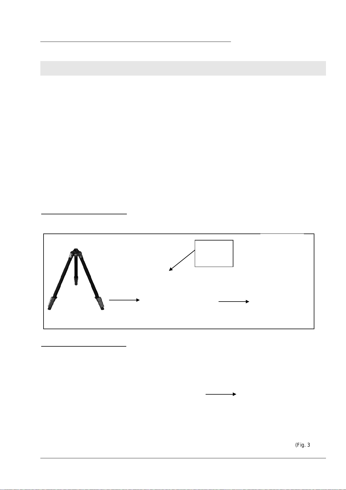
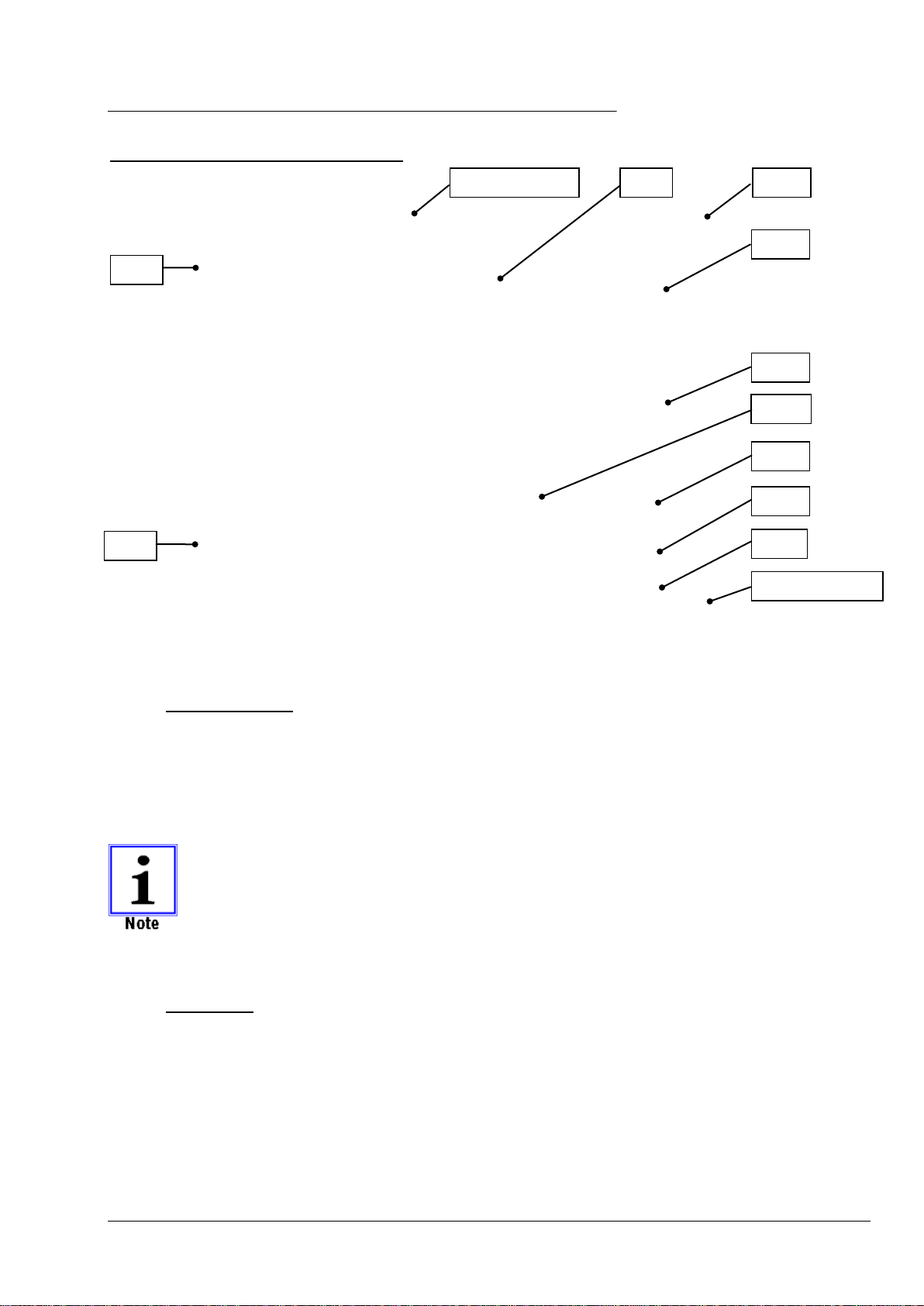
4.1Mounting the laser tripods
1 tripod for tyre measurement:
Insert the laser sensor incl. support tube into the tripod and screw in. (Fig. 1)
2 tripods for rim measurement
Insert tripod head including tube into the tripod and
screw in. (Fig. 2)
Insert the laser sensor including the telescopic tube into
the snap-in fixture on the tripod head. (Fig. 3)
(Fig. 1)
(Fig. 2)
(Fig. 3)
Check for
the
groove!

RUNOUT MEASUREMENT DEVICE RPV1300
RPV1300 Operating Instructions
12
4.2 Installing the software in Windows
•Close all open applications on the computer.
•Insert the USB-Stick (Fig. 4) into the PC.
If the installation wizard does not start automatically, click
Start on the Windows task bar and then click Run.
Enter D:\rpv1300setup_1.04.004.exe, where D is the drive
letter of the USB-Stick.
•Confirm the Windows security warning if necessary and
click Run.
•Read the licence agreement and follow the instructions of
the installation wizard on screen. (Fig. 5)
•When the installation procedure has completed, the
RPV1300 software and the driver for the laser sensors
have been installed on the computer.
•Remove the USB-Stick from the PC after installation.
4.3Installing the laser driver
The driver for the laser sensor is automatically added to the
PC system during installation of the RPV1300 program
•A Windows security information is displayed during
installation of the driver.
In this window, select “Install this driver software anyway”
(Fig. 7)
•When one or more laser sensors are connected to the free
USB ports on the USB hub of the PC after installation, the
new hardware is recognised and added to the system.
(Fig. 8)
(Fig. 4)
(Fig. 5)
(Fig. 7)
(Fig. 8)
(Fig. 6)

RUNOUT MEASUREMENT DEVICE RPV1300
RPV1300 Operating Instructions
13
5 The RPV1300 Program
We have taken great care to ensure that the entire program is straightforward and clear so that
the user can monitor and operate the device at all times with ease.
You will learn how to use this program to determine the rim and tyre geometry of a vehicle
wheel in a very short time.
In just a few steps, help texts and graphical illustrations guide you through the different parts of
the program and provide sufficient information about the program at all times.
Before you begin with your first measurement, however. the most important program
parameters have to be set up for individual use.
5.1Setting up the software
•Start the program.
Click on the RPV1300 icon on the desktop or in Windows select:
START - ALL PROGRAMS - HAWEKA – RPV1300 / RPV1300.
After program start select the option “Settings” for the first basic setting.
The “Start measurement” button only becomes active when at least 2 laser sensors are
connected to the PC.
(Fig. 9)
RUNOUT MEASUREMENT DEVICE RPV1300
RPV1300 Operating Instructions
14
Overview of the program settings page
5.1.1 Customer data:
Enter your company name on the applicable lines so that the name can be included and printed on
the measurement protocol. (Fig. 10)
Select image button:
A company logo can be saved to be displayed on the log.
Supported file types: BMP, JPG, GIF, PNG
The image size is scaled.
Image files that are too small are enlarged, reducing their quality. The smallest format
should be 400 x 200 pixels at 72 dpi.
5.1.2 Language:
Click on the Select Language button to display
menus and all instructions in a different language.
(Fig. 11)
5.1.1
5.1.2
5.1.3
Information bar
5.1.4
5.1.5
5.1.6
5.1.8
5.1.9
Cancel/Back
5.1.7
5.1.10
(Fig. 10)
(Fig. 11)

RUNOUT MEASUREMENT DEVICE RPV1300
RPV1300 Operating Instructions
15
5.1.3 Interface for laser sensor:
After successful installation, new virtual COM interfaces are added to the system, depending on
the number of connected laser sensors.
The entry with the new COM interface can be verified in Windows device manager.
Each laser sensor requires one free USB port.
The supplied USB hub (Fig. 12) is connected to a
USB port on the PC, allowing connection of the
individual laser sensors.
The program can control up to three laser sensors.
(Fig. 13)
When the program has detected a laser sensor it will
display the corresponding serial number.
Description of symbols:
Display is grey. No laser sensor detected.
Display is green. Laser sensor was connected and
detected.
Display is red: Flash test on the laser sensor.
(Fig. 13)
(Fig. 12)

RUNOUT MEASUREMENT DEVICE RPV1300
RPV1300 Operating Instructions
16
5.1.4 Laser symbol information:
During the entire program execution the connection to
the laser sensors and the measurement procedures is
verified and displayed at the top right.
(Fig. 14)
Description of symbols:
Display is grey. The laser sensor is not connected to the
system. Unknown state. (Fig. 15)
The display flashes yellow and red alternately. The program is
attempting to establish a connection with the lasers. (Fig. 16)
Display is green. Connection to laser established. (Fig. 17)
Display is green with a red centre: The connection is
established but no measuring points were found, or flashing
during setup of laser sensor (Fig. 18)
Display is green with a yellow centre: Connection is established
and wheel was detected. Ready to for measurement recording
(Fig. 19)
Display is striped grey/yellow. Laser was removed from the
interface.
(Fig. 20)
Display is red. Error in of measurement recording.
(Fig. 21)
5.1.5 Instructions
Specifying the default for displaying/hiding operating
instructions during measurements. (Fig. 22)
The instructions window can be
displayed/hidden at any point in the
program. Click on the Instructions button
on the program page.
(Fig. 15)
(Fig. 16)
(Fig. 17)
(Fig. 18)
(Fig. 19)
(Fig. 21)
(Fig. 22)
(Fig. 20)
(Fig. 14)
RUNOUT MEASUREMENT DEVICE RPV1300
RPV1300 Operating Instructions
17
5.1.6 Data directory
All vehicle measurements are saved in a log file. The
preset file path is:
My_Documents\UserName\AppData\Haweka\
RPV1300\Database\(Fig. 23)
To change the file location, click on “Folder”:
To reset the default path, click on “Reset”:
5.1.7 Password
This function is used only by our service personnel
to carry out system diagnostics.
This option allows our service personnel to implement
program-specific changes. (Fig. 24)
5.1.8 Saving program settings
All settings must be confirmed by
clicking “Apply settings”.
5.1.9 Advanced settings
Under advanced settings, the user has the
option of personalising the program. (Fig. 25)
To customise settings, select the applicable
parameter in the table and change the value.
The modified entries must be confirmed by
clicking “Accept values” (Fig. 26).
5.1.10System overview
The system overview provides a list of the components
used, the PC, the sensor and the program versions.
This information is used by the service technician to
gain an overview of the system in the event of errors.
(Fig. 27)
(Fig. 23)
(Fig. 26)
(Fig. 24)
(Fig. 27)
(Fig. 25)

RUNOUT MEASUREMENT DEVICE RPV1300
RPV1300 Operating Instructions
18
6 Preparing for measurement recording
Different preconditions have to be met on the vehicle wheel for correct measurement.
•Drive the tyre for approx. 15 min. to warm it up and prevent flat spots
•Check that the vehicle has rims and tires of the same size
•Check that the tire pressure is correct
•Remove any dirt from wheel and tyre and clean these.
•Check wheel for sufficient tread depth (tread lugs have to be clearly visible)
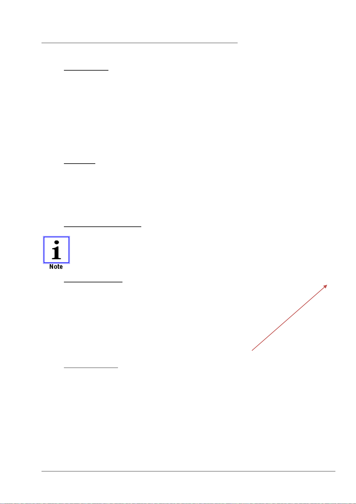
6.1Preparatory measures
Variant 1
Jacking up the car
(Fig. 28)
•Secure vehicle against rolling away.
•Lift the vehicle at the axle to be measured
using a suitable lifting device until the wheel
can be rotated freely.
•Prevent vehicle from inadvertent lowering.
(e.g. support stands)
Variant 2
Vehicle wheel on tyre mounting machine
(Fig. 29)
•Clamp the vehicle wheel using a suitable* lorry
tyre mounting machine, following instructions
and ensuring exact centring.
•The wheel has to rotate freely.
∗
Observe the rotational speed of the
tyre mounting machine.
See table on page 24.
(Fig. 28)
(Fig. 29)
RUNOUT MEASUREMENT DEVICE RPV1300
RPV1300 Operating Instructions
19
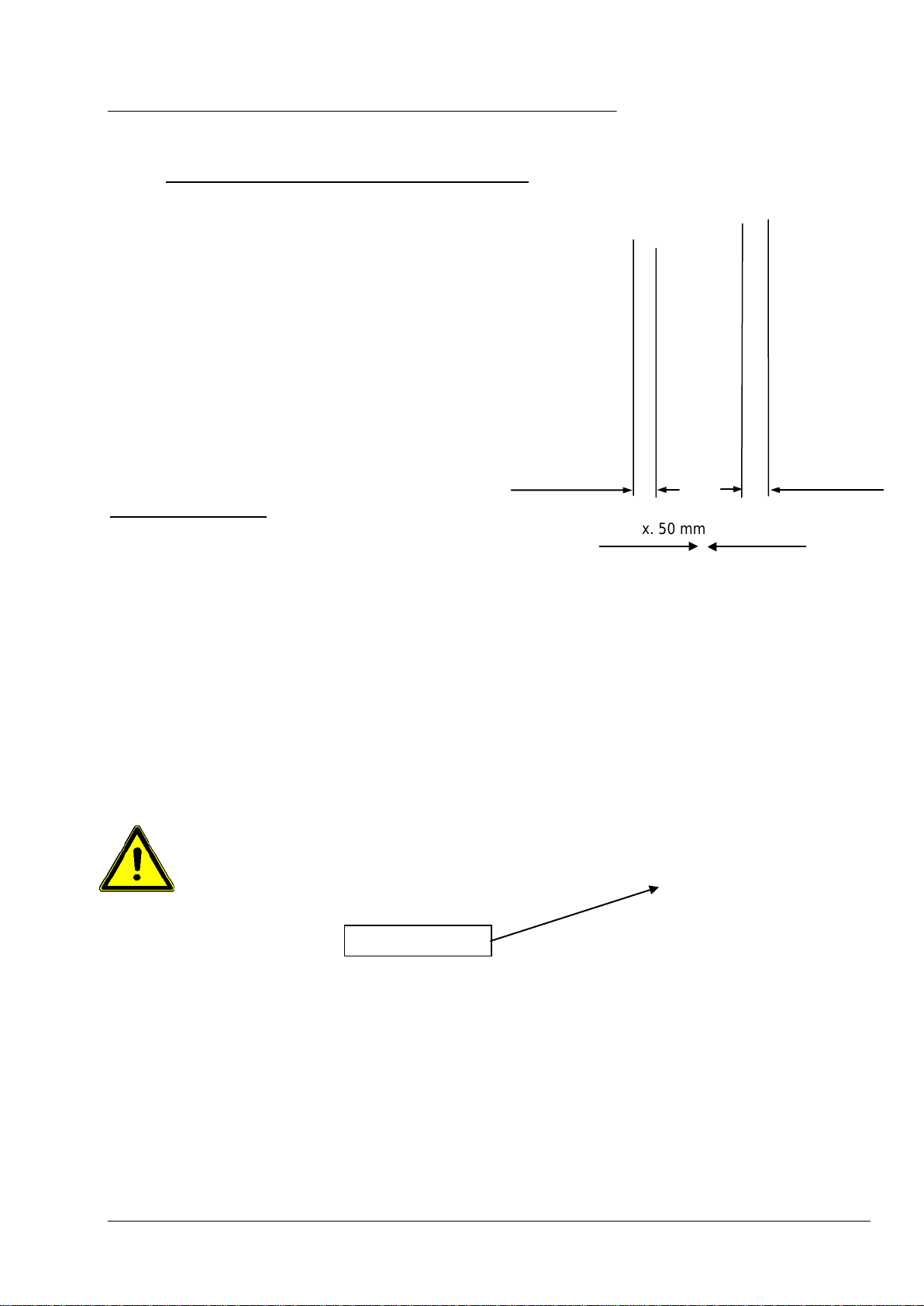
6.1.1 Setup of measuring device on vehicle wheel
Depending on the version, 2 or 3 sensors are
placed at the vehicle wheel.
The positions of the laser sensors on the wheel
are determined to create a distance (A) between
sensor and measuring point in the range of 80 to
120 mm.
(Fig. 30)
Laser sensor for tyre
The laser sensor is placed approx. 50 mm away
from the centre (to the left or right) of the tread so
that it faces a tread lug. (Fig. 31)
When setting up the laser sensors
ensure that all laser sensors are
aligned on a level passing through
the vehicle axle.
The measuring points have to be on a level with the
vehicle axle, with a tolerance of ±1 cm (Fig. 32).
(Fig. 31)
(Fig. 30)
(A)
(A)
Rim measurement
Tyre measurement
(Fig. 30)
approx. 50 mm
Measuring level
(Fig. 32)
Attention
RUNOUT MEASUREMENT DEVICE RPV1300
RPV1300 Operating Instructions
20
7 Measurement recording
7.1 Entering vehicle, wheel and rim data in the program
At least two laser sensors are connected to the PC and the PC is switched on. The program
rpv1300 is running and is set to the start page.
•Click on “Start measurement”.
•Enter vehicle data. (Fig. 33)
Entering the correct wheel geometry with
number of tread lugs and wheel diameter is
absolutely required for evaluation.
•Click “Next” to finish vehicle entry and continue to
the next program page. (Fig. 34)
•Select front or rear axle on the model on the right.
•Enter tyre and rim information in the corresponding
fields.
Information about centring:
How well is the wheel mounted on the hub? (Fig. 35)
GOOD: The distance between inside rim
opening and wheel hub is the same for
the entire circumference.
BAD: The wheel is not fixed centrally on the
wheel hub, the gap is not the same all
around.
NOT TESTED: No information about concentric fit
between wheel and hub.
GAP VALUE: You can enter a value (mm) for the gap measurement here. This information will
later appear as a note on the log.
The gap value has NO influence on the result of the evaluated measuring points!
SUSPENSION: This note field can be used for entering details about the actual situation of the
axle suspension on the vehicle. This information will be displayed on the log.
(Fig. 33)
(Fig. 34)
(Fig. 35)
Table of contents
Other HAWEKA Measuring Instrument manuals


Popular Measuring Instrument manuals by other brands


Kaman
Kaman KDM-8206 Reference manual

GE
GE EPM6000 instruction manual

Johnson Controls
Johnson Controls FMS-1655M installation instructions

Concoa
Concoa Advantium 16 Installation and operating instructions

Renishaw
Renishaw RP1 Installation and user guide

KROHNE
KROHNE OPTIFLEX 2200 Supplementary instructions