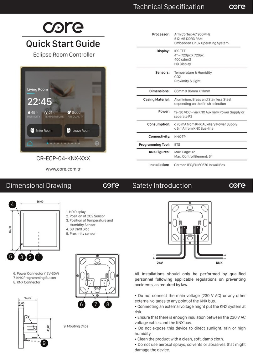
HAWK-I Security 8630B User manual

HAWK-I
USER MANUAL
™
Model 8630B
Hardware Manual
AMOT
CONTROLS
HAWK-I
USER MANUAL
™
Model 8630B
Hardware Manual
AMOT
CONTROLS

HAWK-I
USER MANUAL
i
© 1998 AMOT Controls Corp.
All Rights Reserved
Printed in USA
Trademarks used in this text:
Hawk-I and HawkWin are trademarks of AMOT Controls Corp. Windows and
Windows␣ 95 are registered trademarks of Microsoft Corporation. Modbus is a
registered trademark of Modicon Ltd. Other trademarks and trade names may be
used in this document to refer to either the entities claiming the marks and
names or their products. AMOT Controls Corp. disclaims any proprietary
interest in trademarks and trade names other than its own.
This document is based on information available at the time of its publication.
While efforts have been made to be accurate, the information contained herein
does not purport to cover all details or variations in hardware or software, nor to
provide for every possible contingency in connection with installation, operation,
or maintenance. Features may be described herein which are not present in all
hardware and software systems. AMOT Controls Corp. assumes no obligation of
notice to holders of this document with respect to changes subsequently made.
AMOT Controls Corp. makes no representation or warranty, expressed, implied,
or statutory with respect to, and assumes no responsibility for the accuracy,
completeness, sufficiency, or usefulness of the information contained herein. No
warranties of merchantability or fitness for purpose shall apply.
Use of DANGER, WARNING, CAUTION, and NOTE:
This publication includes DANGER, WARNING, CAUTION, and NOTE
information where appropriate to point out safety related or other impor-
tant information.
DANGER: Hazards which could result in severe personal injury or death.
WARNING: Hazards which could result in personal injury.
CAUTION: Hazards which could result in equipment or property damage.
NOTE: Alerts user to pertinent facts and conditions.
Although DANGER and WARNING hazards are related to personal injury,
and CAUTION hazards are associated with equipment or property damage,
it should be understood that the operation of damaged equipment could,
under certain conditions, result in degraded system performance leading to
personal injury or death. Therefore, comply fully with all DANGER,
WARNING, AND CAUTION NOTICES.

Table of Contents
ii
1. INTRODUCTION
1.1 Easy and Flexible Programming............................. 1-1
1.2 Other Key Features................................................. 1-1
1.3 Scaling and Signal Processing................................. 1-2
1.4 RS–232C Communications Port ............................ 1-2
2. SPECIFICATIONS
2.1 Inputs..................................................................... 2-1
2.2 Outputs .................................................................. 2-1
2.3 Communications.................................................... 2-2
2.4 Display ................................................................... 2-2
2.5 Environment .......................................................... 2-2
2.6 Power Supply.......................................................... 2-3
2.7 Hawk-I Specification Sheet .................................... 2-4
3. INSTALLATION
3.1 Installation Overview ............................................. 3-1
3.2 Recommended Environment .................................. 3-1
3.3 Mechanical Installation .......................................... 3-1
3.4 Wiring Requirements ............................................. 3-4
3.5 Grounding Requirements ....................................... 3-4
3.6 Digital Inputs......................................................... 3-6
3.6.1 Selecting Fault Sensing Switches ........................ 3-6
3.6.2 Dry Contacts ..................................................... 3-6
3.6.3 Sealed and Precious Metal Contacts ................... 3-6
3.6.4 Normally Open and Normally Closed ............... 3-6
3.6.5 Using Relay Contacts as Sensor Switches............ 3-7
3.6.6 Connecting The Digital Inputs .......................... 3-7
3.7 The Thermocouple Inputs...................................... 3-8
3.7.1 Connecting the Thermocouple Inputs ............... 3-8
3.8 The 4-20 mA Sensor Inputs.................................... 3-9
3.8.1 Connecting the 4-20 mA Sensor Inputs ............. 3-9
3.9 The Tachometer Input............................................ 3-9
3.9.1 Connecting the Tachometer Input ................... 3-10
3.10 The Start and Stop Inputs .................................. 3-10
3.10.1 Connecting the Start and Stop Inputs ............ 3-10
3.11 The Power Supply .............................................. 3-10
3.11.1 Connecting the Power Supply ........................ 3-10
3.12 The RS232C Communications Port................... 3-11
3.12.1 Connecting the RS232C Port for Programming 3-11
3.12.2 Connecting the RS232C Port for Monitoring 3-12
3.13 The Configuration Link Input ........................... 3-12
3.13.1 Connecting the Configuration Link Input ..... 3-13
3.14 The Pulse Input.................................................. 3-13
3.14.1 Connecting the Pulse Input ........................... 3-13
3.15 The Standard Relay Outputs .............................. 3-13
3.15.1 Connecting the Standard Relay Outputs ........ 3-13
3.16 The Optional Digital Outputs............................ 3-13
3.16.1 Connecting the Optional Digital Outputs ..... 3-13
3.17 The 4-20 mA Analog Outputs ............................ 3-14
3.17.1 Connecting the 4-20 mA Analog Outputs ..... 3-14
4. TEST AND OPERATION
4.1 Pre-Operation Test Procedure ............................... 4-1
4.2 Initial Check of Hawk-I Operation........................ 4-2
4.2.1 Configure Mode and Run Mode ........................ 4-2
4.3 Troubleshooting the Installation ............................ 4-3
4.3.1 LED Status Indicator ......................................... 4-3
4.4 Hawk-I Does Not Operate ..................................... 4-3
4.5 Digital Input Channel Does Not Function............. 4-3
4.5.1 Common Wiring Problems ................................ 4-4
4.5.2 Intermittent Wiring Problems............................ 4-5
4.5.3 Swapping Channels............................................ 4-6
4.6 Electromagnetic Interference (EMI)....................... 4-6
4.6.1 Symptoms of EMI ............................................. 4-6
4.6.2 Grounding ......................................................... 4-7
4,6,3 Ground Loops ................................................... 4-7
4.7 Before Contacting AMOT ...................................... 4-7
iii

5. MAINTENANCE AND REPAIR
vi
5.1 Maintenance........................................................... 5-1
5.1.1 Cleaning ............................................................ 5-1
5.1.2 Battery Replacement .......................................... 5-1
5.1.3 Fuse replacement ............................................... 5-2
5.2 Repair..................................................................... 5-3
5.2.1 Returning Equipment for Repairs ...................... 5-3
6. CHANGING THE HAWK-I’S CONFIGURATION
6.1 The Hawk-I Keypad ............................................... 6-1
6.2 Gaining Access to the Configuration Menus .......... 6-1
6.3 Moving Up and Down Between Menus.................. 6-2
6.4 Moving From Side to Side in a Menu..................... 6-2
6.5 Revising Data Within a Menu Box......................... 6-2
6.6 Exiting Configuration Mode .................................. 6-3
6.7 Precautions............................................................. 6-3
6.8 Descriptions of Individual Menu Boxes ................. 6-4
6.8.1 Controllers...................................................... 6-4
6.8.2 Analog User Input .......................................... 6-4
6.8.3 Hours Run/Power Down ................................ 6-4
6.8.4 Fault Logging .................................................. 6-4
6.8.5 Digital Inputs ................................................. 6-4
6.8.6 Analog Inputs ................................................. 6-4
6.8.7 Digital Outputs .............................................. 6-4
6.8.8 Analog Outputs .............................................. 6-5
6.8.9 Timers ............................................................ 6-5
6.8.10 Tachometer ..................................................... 6-5
6.8.11 Time of day .................................................... 6-5
6.8.12 User Switches .................................................. 6-5
6.8.13 Average Groups ............................................... 6-5
6.8.14 Split Ranges .................................................... 6-5
6.8.15 User Setpoints ................................................. 6-5
6.8.16 Communications ............................................ 6-5
6.8.17 Test Mode Timer ............................................ 6-6
6.8.18 Diagnostics ..................................................... 6-7
6.8.19 Lock/Unlock ................................................... 6-8
7.VIEW MODE
7.1 Descriptions of Individual Menu Boxes ................. 7-1
7.1.1 Controllers...................................................... 7-1
7.1.2 Analog User Input .......................................... 7-1
7.1.3 Unhealthy Channels ....................................... 7-1
7.1.4 Hours Run/Power Down ................................ 7-1
7.1.5 Fault Logging .................................................. 7-1
7.1.6 Digital Inputs ................................................. 7-1
7.1.7 Analog Inputs ................................................. 7-2
7.1.8 Digital Outputs .............................................. 7-2
7.1.9 Analog Outputs .............................................. 7-2
7.1.10 Timers ............................................................ 7-2
7.1.11 Tachometer ..................................................... 7-2
7.1.12 Time of day .................................................... 7-2
7.1.13 User Switches .................................................. 7-2
7.1.14 Average Groups ............................................... 7-2
7.1.15 Split Ranges .................................................... 7-2
7.1.16 User Setpoints ................................................. 7-2
7.1.17 Run Diagnostics.............................................. 7-3
7.1.18 Lock/Unlock ................................................... 7-4
7.1.19 Test Mode ....................................................... 7-4
vii

1-1
1.INTRODUCTION
The Hawk-I system is a unique, highly advanced, programmable
controller combining the power of a PLC with the easy to use functional-
ity of an embedded control system. This system allows safe, localized
scanning of digital inputs, temperatures, pressures, flows, electrical
currents and voltages, and fluid levels in machinery and industrial
processes. Built-in communications make the Hawk-I a powerful and safe
front end for hazardous-area data acquisition and alarm annunciation.
1.1 Easy and Flexible Programming
The graphical programming interface to the Hawk-I system allows the
user to overcome the rigid constraints of conventional EPROM-based
equipment. AMOT’s innovative Ladder Logic lets even the novice
programmer set up new system functions easily and quickly.
HawkWin, the Windows 95, 98, NT based configuration software used to
program the Hawk-I system, was developed from AMOT’s long experience
in embedded controllers. The most critical problem with embedded control-
lers is the inability to make fast, on-site software changes, because the
programming of a typical embedded controller is contained in an EPROM
chip that cannot be altered. Software changes in such a system must be made
at the factory, not in the field, taking up to several weeks to implement.
Hawk-I and HawkWin were created to overcome this limitation. Almost
any safety shutdown, data monitoring, or alarm function can be rapidly
programmed on-site using HawkWin. Then the function sequence is
downloaded into Hawk-I through a standard RS232 Null Modem cable
from the PC.
1.2 Other Key Features
The Hawk-I is based on an expandable platform. The basic system
supports 16 discrete inputs, 4 power relay outputs, and a speed input to
sense RPM. It can be expanded to include 8 or 16 thermocouples, 8 or
16 4-20 mA loop inputs, 2 PID 4-20 mA loop outputs, and 8 low power
relays. (NOTE: Unit may be configured with no more than 24 analog
inputs total and no more than 16 of one specific type).
A communications option allows connection to a modem or Distributed
Control System (DCS) via Modbus/RTU protocol.
The Hawk-I module features a tactile keyboard (NEMA 4) and a large,
high-contrast, 32-character display with backlight.
1-2
1.3 Scaling and Signal Processing
The Hawk-I contains scaling and linearizing circuits that provide
individual channel readouts in software selectable units such as Centi-
grade and Fahrenheit temperatures, psig, psia, psid, feet and inches,
meters and centimeters, inches of water, etc. Individually set alarm and
shutdown setpoints are available for each channel, as well as multiple
user-defined setpoints. Any channel can be configured to trip when the
channel input is less than or greater than the setpoint. Timer class logic
can also be associated with channels on an individual basis.
Input channels can be grouped together for signal averaging. The Hawk-I
can generate an alarm or shutdown based on the deviation of any single
channel from the average. Each input channel setpoint or averaging
group setpoint can be assigned to any selected digital output.
1.4 RS-232C Communications Port
The RS232C serial data port and Modbus/RTU protocol allow easy
interfacing to many types of PLCs and distributed control systems,
including Modicon, Allen-Bradley, and Fisher Provox. Modbus supports
one master and multiple slave units. Baud rate and Modbus ID number
can be set from the Hawk-I keypad.

2-1
2.SPECIFICATIONS
The Hawk-I is an expandable-platform digital controller with many
available options that allow the user to select a powerful yet economical
control system.
2.1 Inputs
The sixteen discrete digital inputs used in the Hawk-I have volt-free contacts
and are non-incendive; any kind of input switching device can be used. There
is not enough energy in the circuit to ignite any gas mixture that may be
present. The minimum loop resistance for an ‘off’ state is 15kΩ, the scan rate
is 100 msec, and the response time is 100 msec.
The Hawk-I provides a speed input designed for use with an AMOT
magnetic pickup, which senses gear teeth to determine RPM.
The optional J and/or K-type thermocouple inputs may be used with an
expanded Hawk-I system. The available temperature range is -346º to 1940º
F, or -210º to 1060º C. Accuracy is better than 1% of FSD with a 100 ms
scan rate. The thermocouple input field connections are classified as non-
incendive, since a thermocouple is a simple device that cannot store energy.
The field wiring is 37-Way D Type through a DB-37 connector.
The Hawk-I can provide optional 4-20 mA/two-wire analog inputs. These
inputs have an accuracy of ±0.5% of indicated parameter value with a scan
rate of 100 ms. Loop power of 15 Vdc (open circuit) is provided. These
analog inputs are designed for use with transmitters that are approved for use
in a Class I, Division 2 area and are non-incendive. The field wiring is 25-
Way D Type through a DB-25 connector. For hazardous area installations, if
non-approved end devices are used, wiring must pass through an approved
barrier.
2.2 Outputs
The basic Hawk-I system has four relay outputs. The outputs are solid-
state (non-sparking) relays rated at 36Vdc, 1.75A. An external snubber
network is required when switching inductive loads. These outputs are
accessed through two-part Phoenix connectors on the back of the Hawk-I
module. The connectors can accept wire as large as 12 AWG, allowing
long wire runs without excessive signal loss.
2-2
WARNING
SINCE THESE RELAYCIRCUITSTRANSMIT POWER FROM
AUXILIARYEQUIPMENT, THEYARE CLASSED
INCENDIVE. ALL ASSOCIATED WIRING MUST BE
SEPARATED FROM NON-INCENDIVE WIRING BYAN
APPROPRIATE DISTANCE.
A further option allows for eight low power, solid state relays. These
outputs are rated at 100 mA/36 V. Connections are made through a 9-
way, D type connector. One side of the relays is bussed common.
Two optional analog outputs can also be provided. These 4-20 mA
outputs can be used to transmit selected data to a remote receiver. The
accuracy is better than 0.75% of FSD with an update rate of 100 msec.
These analog outputs are designed to be attached to a 4-20mA receiver
that has been approved or recognized for use in a Class I, Division 2 area.
If a non-approved receiver is used, the analog output wiring must pass
through an approved barrier, when used in a hazardous area.
2.3 Communications
In addition to the I/O options, the Hawk-I has a 9-pin RS232C connec-
tor that can be used to connect the Hawk-I system with a modem, DCS,
or a PC for programming and configuration changes. The protocol is
Modbus/RTU. This additional programming capability is further
discussed in a separate AMOT manual that describes the HawkWin
computer program.
Signal levels on the RS232C port may be incendive. Any attached device
within a hazardous area must be approved or recognized for use within
that area.
2.4 Display
The Hawk-I controller has a large, high-contrast, backlit, 32-character
display on a NEMA 4 faceplate. This LCD is 16 character by 2-line.
System faults are identified in plain English, and display messages can be
configured into the Hawk-I unit by the user.
2.5 Environment
The Hawk-I is suitable for use only in Class I, Division 2, Groups A, B,
C and D, or non-hazardous locations. Wiring should be installed by
qualified personnel in compliance with local electrical codes.

Electrical and RF interference immunity is designed into the Hawk-I,
with RFI screening in the case. The unit has a high reliability due to
conservative derating of electronic components. The internal printed
circuit boards are conformally coated for extra environmental protection.
The Hawk-I can operate in temperatures between -20º and 65º Centigrade.
The humidity limits are 5% to 95% non-condensing. The controller is
weather and UV protected, and will withstand vibration up to 10G at 100
Hz. The protective case is sealed to NEMA 4 (IP65, dust tight and protected
from water jets) from the front panel when properly installed.
2.6 Power Supply
The Hawk-I can be powered by either 12Vdc or 24Vdc. The 12-V input
can accept DC ranging from 9V to 18V. The 24-V input can accept DC
ranging from 18V to 36V. The supply should be capable of delivering 1A.
Maximum ripple should be 1V P-P. Power is supplied through a terminal
block on the rear of the Hawk-I.
2-3 2-4
Hazardous Approvals:
ETL:Class 1, Division 2
Groups A, B, C, & D
ETLFM 3810 CETL
FM 3611
CAN/CSA C22.2 No. 142
CAN/CSA C22.2 No. 2B
B.A.S.E.E.F.A.: Ex N II C
Power Requirements: Table A
Voltage: 24 Vdc (18-36 Vdc)
12 Vdc (9-18 Vdc)
Current: 500 mA max.(24V)
800 mA max. (12V)
Ripple: <1V pk-pk
Environment:
ETL B.A.S.E.E.F.A.
Temperature: 0°to 150°F 0°to 122°F
(-18°to 65°C) (-18°to 50°C)
Vibration: 0-10g @ 100 Hz
Sealing: NEMA4 from Front Panel
EMC: IEC 801-2(ESD), 801-3(RF Immunity)
Display:Table E
Type:Backlit LCD
Characters: 16 Chars X 2 Lines
Char Size: 8.05 X 5.5mm
Digital Inputs (Non-Incendive):
Type:Volt-Free Contacts
Number:16
Open Circuit: > 15 k ohms
Hawk-I™Hardware Specifications

2-4
Hazardous Approvals:
ETL: Class 1, Division 2
Groups A, B, C, & D
ETL FM 3810 CETL
FM 3611
CAN/CSA C22.2 No. 142
CAN/CSA C22.2 No. 2B
B.A.S.E.E.F.A.: Ex N II C
Power Requirements: Table A
Voltage: 24 Vdc (18-36 Vdc)
12 Vdc (9-18 Vdc)
Current: 500 mA max.(24V)
800 mA max. (12V)
Ripple: <1V pk-pk
Environment:
ETL B.A.S.E.E.F.A.
Temperature: 0°to 150°F 0°to 122°F
(-18°to 65°C) (-18°to 50°C)
Vibration: 0-10g @ 100 Hz
Sealing: NEMA4 from Front Panel
EMC: IEC 801-2(ESD), 801-3(RF Immunity)
Display: Table E
Type: Backlit LCD
Characters: 16 Chars X 2 Lines
Char Size: 8.05 X 5.5mm
Digital Inputs (Non-Incendive):
Type: Volt-Free Contacts
Number:16
Open Circuit: > 15 k ohms
Hawk-I™Hardware Specifications
2-5
Speed Input (Non-Incendive):
Type: Magnetic Pickup
Number: 1
Signal: Zero Crossing >2V pk-pk
Analog Inputs (Optional): Table C
Type: 4-20mA, 2-wire Transmitter,
(Non Incendive)
Number: 8 or 16
Accuracy: Better than 1% of FSD
Loop Power: 15 Vdc provided by the Hawk-I™
Thermocouple Inputs (Optional): Table C
Type: J and/or K, (Non Incendive)
Number: 8 or 16
Accuracy: Better than 1% of FSD
Relay Outputs: Table B
Type: DC Solid State Relay
Number: 4
Rating: 3-36 V at 1.75 A (Continuous)
Isolation: 4 kV
Digital Outputs (Optional): Table B
Type: Solid State Relay, Common Ground
Number: 8
Rating: 36 V at 100 mA
Isolation: 1.5 kV (min)
Analog Outputs (Optional): Table D
Type: 4-20 mA (2-wire)
Number: 1 or 2
Accuracy: Better than 0.75% of FSD
Communications: Table F
Standard: RS232C
Protocol: MODBUS-RTU
Baud Rates: 300-19,200 Baud
Hawk-I™Hardware Specifications

2-6
8630B 1 1 0000
Basic
Model
Number
Model Code
Table C
Table D
Table E
Table F
Table A
Power Source
Code Input Power Options
1 24 VDC (18-36)
5 12 VDC (9-18)
Table B
Relays
Code Relay Options
1 4 DC Relays
3 4 DC Relays + 8 Aux. Outputs
Table C
Extended Board
Code Extended Input Options
0 Extended Board not Fitted
1 16TC Inputs
2 8 (4-20mA) Inputs
3 16TC Inputs + 8 (4-20mA) Inputs
4 8TC Inputs
5 16 (4-20mA) Inputs
6 8TC + 16 (4-20mA) Inputs
Table D
Analog Output
Code PID Options
0 PID Board not Fitted
1 Qty. 1 - PID for Grounded Load
2 Qty. 2 - PID for Grounded Load
Note: Extended Input Board must be
Fitted for use with PID Options 1 & 2
Table E
LCD
Code LCD Options
0 without Backlight
1 with Backlight
Table F
Communications
Code Options
0 HawkWin
1 HawkWin + Data Out
2 HawkWin + MODBUS
Basic Unit

3.INSTALLATION
This chapter covers only the physical installation of the Hawk-I. The
Hawk-I digital controller must be programmed with a set of user-selected
functions before it can be put into service. The user first creates a
customized program for the Hawk-I with AMOT’s HawkWin software,
which is installed in an IBM-type host computer. Then the customized
program is downloaded from the PC into the Hawk-I. Once the Hawk-I
is in service, the program can be updated using the built-in keypad.
For further information about programming your Hawk-I with HawkWin
software, please consult AMOT’s HawkWin Programming Manual.
3.1 Installation Overview
The Hawk-I is often installed in a conventional equipment cabinet of the
enclosed type that can be used to hold a variety of electronic and
pneumatic control equipment. Mounting brackets are provided to hold
the unit in place. The environmental limitations listed on the Specifica-
tions Sheet should be observed. The Hawk-I is designed to be non-
incendive for hazardous atmospheres, but retaining the non-incendive
characteristics of the equipment depends critically on proper installation,
good wiring practices, and the use of certified (or listed) end devices.
3.2 Recommended Environment
The Hawk-I is designed for continuous use (100% duty cycle) in an
ambient temperature ranging from 0º F to 150º F (-18º C to 65º C)
with a humidity of 5% to 95% (non-condensing). Site vibration must
not exceed 10G at 100 Hz.
3.3 Mechanical Installation
The Hawk-I enclosure requires a 1⁄2 DIN cutout of 3.7 ±0.1” by
7.3 ±0.1”, as dimensioned in Fig. 3-1.
To install the unit in a panel:
1. Insert the Hawk-I unit from the front of the panel.
2. Slide the two mounting brackets into the grooves along the
sides of the enclosure.
3. Install the two socket-head screws into the grooves to clamp
the unit in place. Note that to avoid stripping the threads, the
screws must not be overtightened.
4. See Figs. 3-1 and 3-2 (AMOT Drawing No. 68630B-SD)
and the following text for wiring connections.
3-1

3-2
4–20mA INPUTS / OUTPUTSTHERMOCOUPLES
DISCRETE INPUTS–VOLT FREE CONTACTS
CONFIG
LINK
PLS
IN
N/O
START
N/C
STOP
MAGNETIC
PICK-UP
C
O
M
C
O
M
C
O
M
C
O
M
C
O
M
16151413121110987654321
NON–INCENDIVE FIELD WIRING CONNECTIONS FOR CLASS 1, DIVISION 2, GROUPS A, B, C & D
+–
36 VDC 1.75A MAX 36 VDC 100mA MAX
AUX.
OUTPUTSRS232C
DC POWER
18–36V
++
––+–+–+–
N/C N/C
RELAY 1 RELAY 2 RELAY 3 RELAY 4
WARNING AVERTISSEMENT
EXPLOSION HAZARD – DO NOT DISCONNECT WHILE CIRCUIT
IS LIVE UNLESS AREA IS KNOWN TO BE NON–HAZARDOUS
RISQUE D'EXPLOSION–NE PAS DEBRANCHER TANT QUE LE CIRCUIT EST SOUS
TENSION, A MOIN QU'IL NE S'AGISSE D'UN EMPLACEMENT NON DANGEREUX
Panel Cutout
7.3 + 0.1"
Panel Cutout
3.7 + 0.1"
–
–
Figure 3-1. Back view of the HAWK-I, showing connection points and panel cutout dimensions for mounting.
[

68630B–SD
DWG
NO. SHEET 1 OF 2
SHEET 1 OF 2
2
3
13
16
15
14
12
11
10
9
8
7
6
5
4
1+
+
+
+
+
+
+
+
+
+
+
+
+
+
+
+
-
-
-
-
-
-
-
-
-
-
-
-
-
-
-
-
1TC
2TC
3TC
4TC
5TC
6TC
7TC
8TC
9TC
10TC
11TC
12TC
13TC
14TC
15TC
16TC
20
21
22
23
24
25
26
27
28
29
30
31
32
33
34
35
16
THERMO -
COUPLES
10
9
9
8
8
7
7
6
6
5
5
4
4
3
3
2
2
1
1
9
8
7
6
5
4
3
2
1
TACHO (ELECTROMAGNETIC
PICKUP HEAD) COMMON
STOP N/C
START N/O
+
–
S1
S1
PULSE INPUT (TTL LEVELS)
CONFIG. LINK
TO MODEM
RS232C PORT
4
CD
DSR
RXD
TXD
CTS
DTR
RI
COMMON
RTS
AUX 1
AUX 2
AUX 3
AUX 4
AUX 5
AUX 6
AUX 7
AUX 8
AUX _COM
3 5
24V
+
–
LOAD
8 AUXILLARY
OUTPUT S
MATL :
FINISH :
TITLE :
HAWK - I SYSTEM DIAGRAM
AMOT
CONTROLS
SIZE
B68630B - SD
DWG NO
RICHMOND, CA USA – BURY ST. EDMUNDS, SUFFOLK, ENGLAND
DWG CONTROL USA
DRAWN: EW
CHKD:
DATE:
FILE:
APPROVAL:
SCALE:
2 MAY 97
68630BSDS1r4.DWG
MODEL
8630B
REDRAWN/ADDED SHEET 2
REVISION RECORD
4
REV
09/09/98
DATE
DKH
BY REMOVE ALL BURRS AND SHARP EDGES
SURFACE
ROUGHNESS
DO NOT SCALE DRAWING
.XX
.XXX
.XXXX
+
–
+
–
+
–+
–
+
–
ANGLES
FRACTIONS
TOLERANCES UNLESS OTHERWISE SPECIFIED
DIMENSIONS ARE IN INCHES [MILLIMETERS]
AUX OUTPUTS RS232C
DB9 FEMALE DB9 MALE
5 9 4 23 1 1 7
82 3 4
6
6
6
78 9 5
POWER CHASSIS
GND
++
––+–+–+–
+
+–
–+–+–+–
RELAY
1 2 3 4
RELAY OUTPUTS
1 3 4 5 6 7 8
21 3 4 5 62
18–36V DC
1CHASSIS
GND
3 3 3 3 3 3 2 2 2 2 2 2 2 2 2 2
5 4 3 2 1 0 9 8 7 6 5 4 3 2 1 0
123456789
1
0
1
1
1
2
1
3
1
4
1
5
1
6
16
53
489 76 5 3 2 2 2
90 0 0
00 8 7
1
66
53
442
99 8 7
15
34
2
9 8 8
77165
34
21
53 21 3 21
3333
333 2
2
2 2
2
222 1
1
11
1 1
1 1 2
2 1 1
1
222
11
2
0
0
4
44 4
9
9
6
66
8
8
7
7
5
55
3
33 3
1
1
11
11 1 1 1 11
12
22
2
04 96 87531 12 04 96 87531 12
111111 1
65 4 3 247
THERMOCOUPLES
DB37 FEMALE
4–20mA INPUTS/OUTPUTS
DB25 FEMALE
DISCRETE INPUTS
C CCC
C1, C2, C3, C4,
COMMON
CH1
CH2
CH3
CH4
CH5
CH6
CH7
CH8
CH9
CH10
CH11
CH12
CH13
CH14
CH15
CH16
16
DISCRETE
INPUTS
VOLT FREE
CONTACTS
14
1, 2, 3, 4, 5, 6, 7, 8
15
16
17
18
19
20
21
10
11
12, 13
1LP
2LP
3LP
4LP
5LP
6LP
7LP
8LP
LOOP POWER (15V MAX)
8 LOOP INPUTS
4–20mA
ANALOG OUT 1 (0–24mA)
ANALOG OUT 2 (0–24mA)
ANALOG OUTPUT RETURN
MA
–+
+
THIRD ANGLE PROJECTION
NOTES: UNLESS OTHERWISE SPECIFIED
DC INPUT POWER: 36V 500mA MAX
(18V 800mA MAX 12V INPUT)
SOLID STATE RELAY OUTPUTS RATED 5–36V 1.75A MAX
AUXILLARY OUTPUTS– 36V 100mA MAX
NULL–MODEM TYPE CONNECTION REQUIRED FOR
INTERFACE TO A COMPUTER
PIN 5 OF AUXILLARY OUTPUT CONNECTOR MUST BE
CONNECTED TO AUX POWER GROUND
SNUBBER DIODE REQUIRED FOR INDUCTIVE LOADS
UNDOCUMENTED PINS SHOULD REMAIN DISCONNECTED
1.
2.
3.
4.
5.
6.
7.
MODEL NO. SHEET NO.
8630B__3___
8630B__6___
1
2
AMOT CONTROLS CORPORATION RESERVES
PROPRIETARY RIGHTS TO THIS DRAWING
AND THE DATA SHOWN THEREON.
IT IS SUBMITTED IN CONFIDENCE FOR QUOTATION
OR ORDER OF THE PRODUCT SHOWN ONLY
SAID DRAWING AND/OR DATA ARE NOT
TO BE USED OR REPRODUCED FOR
ANY PURPOSE WITHOUT THE CONSENT OF
AMOT CONTROLS CORPORATION
Figure 3-2, Sheet 1

THIRD ANGLE PROJECTION
LOOP POWER #1 (15V MAX)
LOOP POWER #2 (15V MAX) 9,25
22, 23, 24
14
15
16
17
18
19
20
10
11
12.13
21
1
2
3
4
5
6
7
8
1LP
2LP
3LP
4LP
5LP
6LP
7LP
8LP
LP9
LP10
LP11
LP12
LP13
LP14
LP15
LP16
8 LOOP INPUTS
4–20mA
8 LOOP INPUTS
4–20mA
ANALOG OUT 1 (0–24mA)
ANALOG OUT 2 (0–24mA)
ANALOG OUTPUT RETURN
MA
–+
+ +
4–20mA INPUTS/OUTPUTS
DB25 FEMALE
3
15
22
14
21
13
20
1 2
2 9 2
180
266
5 4 49 8
77 5
3
1 1 2
11
1 1 1 16
389 76 5 3 2 2 2
90 0 08 7
1 3 29 8 7
15
34
21 65
34
21 3 21 3 21 33
33 2
2
2 2
2
1
1
11
1 1 1
65 4 3 247
THERMOCOUPLES
DB37 FEMALE
04 96 87531 1204 96 87531 12
0 4 4
9653 3
1
11 1 1 1 11 2CC
DISCRETE INPUTS
RELAY
4 6 8753 1
12
2CC
04 96 87531 12
C1, C2, C3, C4,
COMMON
CH1
CH2
CH3
CH4
CH5
CH6
CH7
CH8
CH9
CH10
CH11
CH12
CH13
CH14
CH15
CH16
16
DISCRETE
INPUTS
VOLT FREE
CONTACTS
+–
18–36V DC
1CHASSIS
GND
POWER CHASSIS
GND+ –
1 3 4 5 62
6
+–+–+–+–
+–+–+–+–
1 2 3 4
RELAY OUTPUTS
7 81 3 4 5 62
AUX OUTPUTS
DB9 FEMALE
RS232C
DB9 MALE
5 9 4 23 1 1 7
82 3 4
66
78 9 5
9
8
7
6
5
4
3
2
1
TO MODEM
RS232C PORT
4
CD
DSR
RXD
TXD
CTS
DTR
RI
COMMON
RTS
10
9
8
7
6
5
4
3
2
1
TACHO (ELECTROMAGNETIC
PICKUP HEAD) COMMON
STOP N/C
START N/O
+
–
S1
S1
PULSE INPUT (TTL LEVELS)
CONFIG. LINK
8
THERMO-
COUPLES
2
3
8
7
6
5
4
1+
+
+
+
+
+
+
+-
-
-
-
-
-
-
-
1TC
2TC
3TC
4TC
5TC
6TC
7TC
8TC
20
21
22
23
24
25
26
27
2 2 2 2 2 2 2 2
7 6 5 4 3 2 1 0
12345678
68630B–SD
DWG
NO. SHEET 2 OF 2
9
8
7
6
5
4
3
2
1AUX 1
AUX 2
AUX 3
AUX 4
AUX 5
AUX 6
AUX 7
AUX 8
AUX _COM
3 5
24V
+
–
LOAD
8 AUXILLARY
OUTPUT S
SHEET 2 OF 2
MATL :
FINISH :
TITLE :
HAWK - I SYSTEM DIAGRAM
AMOT
CONTROLS
SIZE
B68630B - SD
DWG NO
RICHMOND, CA USA – BURY ST. EDMUNDS, SUFFOLK, ENGLAND
DWG CONTROL USA
DRAWN: EW
CHKD:
DATE:
FILE:
APPROVAL:
SCALE:
2 MAY 97
68630BSDS2r4.DWG
MODEL
8630B
09/09/98
DATE
DKH
BY REMOVE ALL BURRS AND SHARP EDGES
SURFACE
ROUGHNESS
DO NOT SCALE DRAWING
.XX
.XXX
.XXXX +
–
+
–
+
–+
–
+
–
ANGLES
FRACTIONS
TOLERANCES UNLESS OTHERWISE SPECIFIED
DIMENSIONS ARE IN INCHES [MILLIMETERS]
REDRAWN/ADDED SHEET 2
REVISION RECORD
4
REV
AMOT CONTROLS CORPORATION RESERVES
PROPRIETARY RIGHTS TO THIS DRAWING
AND THE DATA SHOWN THEREON.
IT IS SUBMITTED IN CONFIDENCE FOR QUOTATION
OR ORDER OF THE PRODUCT SHOWN ONLY
SAID DRAWING AND/OR DATA ARE NOT
TO BE USED OR REPRODUCED FOR
ANY PURPOSE WITHOUT THE CONSENT OF
AMOT CONTROLS CORPORATIONFigure
Figure 3-2, Sheet 2

3.4 Wiring Requirements
The Hawk-I is Class I, Division 2 non-incendive equipment. The wiring
to the fault and sensing switches does not require explosion proof conduit
and housings. Such wiring cannot be the cause of a fire or an explosion.
The wiring must be kept separate from that of other electrical systems. If
the Hawk-I wiring is in the same enclosure as other wiring, keep a
minimum of two inches (2 in.) separation from the other wiring, and
securely hold the wiring in place by tie wraps or other means. Even
though explosion-proof conduit is unnecessary, give the wiring proper
mechanical protection. Use wire of good quality and of an insulation type
suitable for the environment.
WARNING
POWER AND HAZARDOUS AREA WIRING SHOULD BE
INSTALLED ONLY BY QUALIFIED PERSONNEL
Because of the small currents and voltages used, keep the sensor wiring
dry and keep splices to a minimum. If crimp-type wire terminations are
installed, use a crimping tool rated for use with the wire size and the lug.
Mismatch of a crimping tool to the wire and lug is a major source of poor
connections. Inspect each lug for correct compression of the crimp on the
cable conductor and the insulation.
Where conduit is used for protection of wiring, position it to avoid the
collection of moisture. In junction boxes or sensor enclosures where open
terminals are present, drain holes are recommended. The sensitivity of
the system to wiring practices is very low, but the value of good wiring
cannot be overestimated in the installation of electrical equipment.
3.5 Grounding Requirements
The back of the Hawk-I has 5 circuit ground terminals (see Fig. 3-1) that
are labeled COM (common), and 2 equipment ground terminals that are
labeled with an earth ground symbol.
There is also a power supply return terminal labeled with a minus (-)
sign. These terminals are not interchangeable, and if they are improperly
connected, the Hawk-I may not function properly.
There are three basic purposes for a ground or common terminal. The first
purpose is to ensure safety for operating personnel by providing electrical
equipment with a direct connection or short circuit to the earth. The second
purpose is to provide a direct connection to a circuit return point in a signal
circuit, and the third purpose is to provide a return circuit for a power supply.
These three different types of grounds must not be carelessly connected
together, even though they are all referred to as grounds.
3-4
For example, on the back of the Hawk-I, the sixteen discrete digital
switching inputs have four interconnected circuit return points labeled
COM. The circuit returns for the digital inputs can be connected to any
of these COM points. The COM terminals are input circuit grounds,
and serve to complete the digital switching circuits. They are not power
supply grounds or equipment safety grounds, and they must not be
connected to the dc power supply or the protective or chassis earth
ground connection.
The protective or chassis ground connection should be kept completely
separate from the circuit ground. The protective ground is intended to
keep the metal chassis of the Hawk-I at the same voltage as its surround-
ings, thus protecting the user from accidental electrical shock. This
requires a separate grounding wire (minimum size 14 AWG) that is not
connected to any other grounds. This protective ground wire should be
connected to the earth-ground terminal bolt on the Hawk-I’s back panel
and then bonded to a good earth ground connection point.
The negative ground for the dc power supply connection is a power
supply ground, and should be connected to the terminal labeled with a
minus (-) sign just below the word POWER on the back panel.
If shielded cable is used to run input wires to the Hawk-I, the shields of
the cables should be connected to the protective ground, not COM. Note
also that cable shields should be grounded only at the Hawk-I and
nowhere else. If a cable shield is grounded at more than one point,
“ground loop” currents may flow through the shield, making it useless.
Under normal conditions, shielded cable is recommended for the
RS232C, thermocouple, and analog loop connections.
The user should follow these simple guidelines and avoid improper intercon-
nections between circuit ground, protective ground, power supply ground,
and cable shield ground. Many hard-to-diagnose equipment problems,
including intermittent problems caused by transient electrical interference,
can be prevented by careful and effective grounding.
If your installation has unusually high levels of electrical interference,
special grounding arrangements may be required. Consult your AMOT
service representative for further details.
3-5
Table of contents
Popular Controllers manuals by other brands

Superior Electric
Superior Electric STABILINE WHR34 S Series instructions
Navien
Navien HotButton NPE-ODC installation manual
Siemens
Siemens 7SR224 manual

Integra
Integra PIPETBOY acu 2 operating instructions

Norac
Norac UC4+ New Navigator 2007+ installation manual
Parker
Parker ER032 Maintenance Instructions & Parts List
