Table of Contents
Gladiator Doppler Microwave Series
2
Contents
PROPRIETARY NOTICE
The information contained in this publication is derived in part from proprietary
and patent data. This information has been prepared for the express purpose
of assisting operating and maintenance personnel in the efficient use of the
instrument described herein. Publication of this information does not convey any
rights to use or reproduce it, or to use for any purpose other than in connection
with the installation, operation and maintenance of the equipment described
herein.
WARNING
This instrument contains electronic components that are susceptible to damage
by static electricity. Proper handling procedures must be observed during the
removal, installation, or handling of internal circuit boards or devices:
Handling Procedure:
1. Power to unit must be removed prior to commencement of any work.
2. Personnel must be grounded, via wrist strap or other safe, suitable means,
before any printed circuit board or other internal devices are installed,
removed or adjusted.
3. Printed circuit boards must be transported in a conductive bag or other
conductive container. Boards must not be removed from protective container
until the immediate time of installation. Removed boards must be placed
immediately in a protective container for transport, storage, or return to
factory.
Overview 3
Principle of Operation 3
Typical Uses 3
Function 3
Features 3
Dimensions 4
Remote Microwave System 4
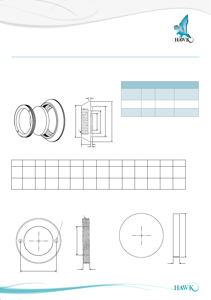
MA Series Weldments and Windows (UHMW / PTFE) 5
MA Series Weldments and Windows (Ceramic) 6
MD Series Weldments and Windows 7
Weldments and Windows (Ceramic Tile & Firebrick
Assemblies) 8
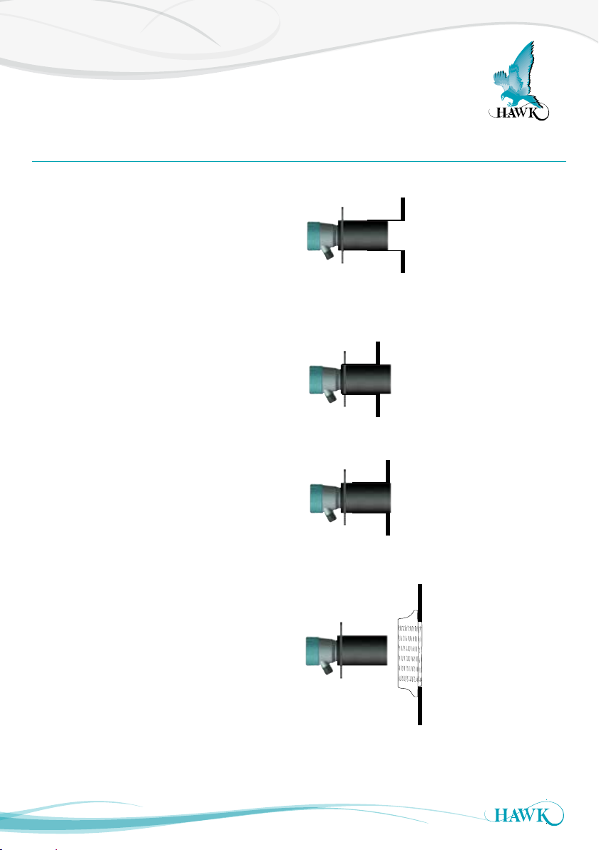
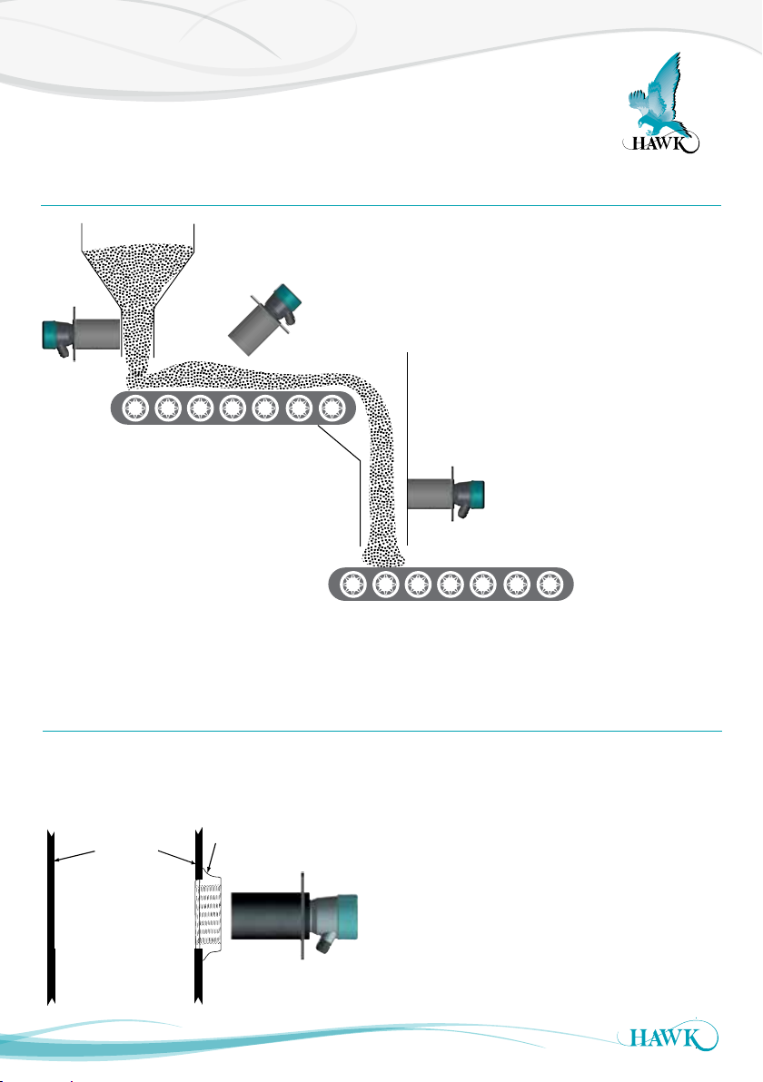
Mounting 9
General Guidelines 9
Mounting 10
Mounting With Windowed Weldments 10
Wiring 11
Remote System Connection - HAWK Supplied Cable 11
Remote System Connection - Customer Supplied Cable
12
Alternate Cable Type Between
Amplifier and Sensors 12
Integral System Connection 13
Wiring - Relay Functions 14
Functionality Layout 15
Integral System 15
Commissioning 16
Remote System 16
Integral System 17
Remote Software 18
Operational Diagnostics 18
Remote Software 19
Main Menus & Interface 19
Quickset Menu - Parameters 20
Advanced Menu - Parameters 21
Integral Test Switch 22
Integral Receiver Test Switch Functions 22
Troubleshooting 23
Troubleshooting 23
Error Codes 24
Safety Information 25
FCC Regulations 25
Part Numbering 26
Remote Version 26
Integral Version 27
Accessories 27
MA Series Mounting Accessories 28
MD Series Mounting Accessories - Kit 28
MD Series Mounting Accessories - Parts 29
Specications 30
A Higher Level of Performance 31