Hawker EnerSys LifeSpeed IQ User manual
ENGLISH
SAFETY INSTRUCTIONS
GOALS OF THIS MANUAL
This manual is aimed at any authorized personnel wanting
to use a 3-phase LifeSpeed IQTM charger to recharge lead
acid motive power batteries (vented, Hawker XFCTM, Gel or
Water Less®/Water Less®20 ranges)
This manual contains information on:
• Charger functionality.
• Use and setting of charger parameters.
• Technical specifications of the LifeSpeed IQ chargers.
EnerSys®intends to provide clear and simple information
in this manual, and assumes no responsibility for misunder-
standing or improper interpretation of the information.
The owner of the equipment is required to preserve this
manual during the life of the equipment and to transfer said
manual to any subsequent purchaser.
WARRANTY
Warranty is offered by the manufacturer based on local
regulations. Please contact your local distributor for further
information.
RECOMMENDATIONS
Recommendations for safe operation
This manual should be carefully read, prior to using the
equipment, by anyone intending to use the charger.
The
LifeSpeed IQ
:
• Must not have its air circulation impaired in any way,
primarily around the air inlet areas.
• Dust accumulation must be removed every 12 months.
• Must be used within its protection norms, and never
be directly in contact with water.
• Must be used only within the temperature range
specified in the technical specifications.
• Internal connection torques must be checked once a
year.
• Must not be installed on a surface subject to high
vibration levels (proximity of motors, compressors, etc.).
• Must not be installed close to the batteries in order to
avoid any gassing that could damage it prematurely.
• Must not be installed in arduous environments such as:
• Harbour applications (saline environment)
• Close to cold stores
• External locations with exposure to wind and rain
Operator safety
All proper precautions must be observed when the
equipment is used in areas where accidents are possible.
Ensure proper ventilation when the charger is used with
lead-acid batteries, due to gassing. Never disconnect the
battery during the charging process.
General warnings
Requirements for use:
• The equipment must be properly grounded (earthed).
• The input voltage must match the charger requirements.
• The battery voltage must match the charger’s
capabilities.
• The battery capacity is within the charger’s range.
ELECTRICAL SAFETY
Safety regulations and requirements must be observed.
Safety devices installed on the electrical supply to the
chargers must be of the proper type and rating. It is
important to ensure that only fuses of the proper
capacity should be used if they need to be replaced.
The equipment must be totally disconnected from all power
sources (mains supply and battery) before it can be opened
for inspection or servicing. The battery can only be discon-
nected after the charge has been stopped by pushing the
Stop/Start button. Access to the inside of the charger
should be restricted to authorized maintenance personnel.
Please consult a qualified factory representative about any
problems or questions related to the installation of this
unit.
LIMITS OF USE
This charger is designed to be used in a sheltered area.
It is designed exclusively to recharge lead batteries in an
industrial environment.
PRODUCT RECYCLING - DESTRUCTION
When this charger becomes obsolete, it can be recycled
or destroyed by authorized facilities. Local regulations will
prevail and must be followed.
MODIFICATIONS AND IMPROVEMENTS
EnerSys reserves the right, at any time, to modify or
improve its products, without any obligation to update
this product or this manual accordingly.
The customer is not permitted to modify the product from
its original design and configuration (e.g. fitting additional
modules).
Any changes made by the customer could affect the
product performance and invalidate the warranty.
RECEIVING - STORAGE
Upon receipt, please inspect visually the exterior of the
charger for any physical damage. If necessary, proceed
within 24 hours with the usual claims procedure with the
transport company.
If the charger is to be stored before use, it should remain
in the original packaging, carefully closed. Store in a clean,
dry area at a moderate temperature (0 °C to +40 °C). If the
equipment is stored at a temperature below 15°C, it must
be gradually (24 hours) restored to operating temperature
before use, to prevent the risk of condensation that could
cause electrical faults and short-circuits.
INFORMATION PLATE
Located on either side of the charger.
EC DECLARATION OF CONFORMITY
EnerSys hereby declares that the chargers in the
LifeSpeed IQ range covered by this declaration
conform to European Directives:
Directive 2006/95/EC (Low Voltage Directive):
EN60950-1
Directive 2004/108/EC (ElectroMagnetic Compatibility):
EN61000-6-2, EN61000-6-4:
Immunity and emissions limits for industrial electronics
(class A- Industrial Environments)
Directive 2002/95/EC (RoHS)
Safety and use instructions LifeSpeed IQ
TM
- 3-phase chargers
DESCRIPTION & USE
INTRODUCTION
The LifeSpeed IQTM range of chargers is designed to recharge
24 V, 36 V, 48 V, 72V or 80 V batteries with 3-phase mains
supply. The microprocessor-controlled unit automatically
recognises the battery (voltage, capacity, charge level, etc.)
and very effectively analyses its condition for optimum
handling. Several charging profiles are available (vented
lead/acid batteries, Hawker®XFCTM batteries, gel batteries
or
Water Less®
/
Water Less®
20 batteries) depending on the
configuration selected by the user. The capability for
desulphation, equalisation and refresh charging is also
included.
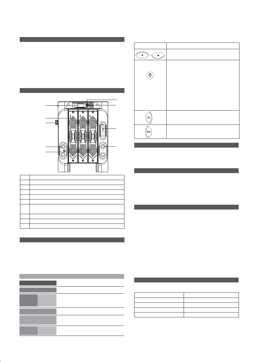
EXTERNAL COMPONENTS
Presented below:
Ref. Function
1. Control Panel with LCD display
2. USB port
3. Navigation button
4. Modules
5. Input cable
6. Connectors for options:
Ethernet, Electrovalve, Lifenetwork IQ
7. Output cables
8. Output cables (dual harness only)
9. Ventilation panels
Figure 1: Principal components of the charger.
CONTROL PANEL
Incorporates LCD Display, USB port and navigation button.
LCD Display
The display is fitted with 5 different colours indicating the
status of the charger:
Navigation button
Functions of the keys
The keys offer the following general functions:
Key Function
Navigation in the menu.
Start/End of list (Press 2 seconds)
The central button is equipped with
a two-coloured LED Green/Red
(Green: charger is waiting, Red charger
operating)
GREEN/RED Stop or Start of charge
Selection of active menu or validation
of value stored
Cancel the value stored
(Press 2 seconds)
Start an equalisation charge.
Access to a sub-menu.
Access to the menus (press 3 seconds)
Close the window.
UNPACKING
The charger is delivered with the following:
• 2 m AC mains cable.
• 3 m DC battery cable.
• This technical manual.
MECHANICAL INSTALLATION
The charger is intended to be floor standing and must be
installed in the vertical orientation. The distance between
2 adjacent chargers should be at least 0.3 m.
See paragraph
Recommendations
and avoid areas where
the chargers may be splashed with water, or saline
environments.
ELECTRICAL CONNECTIONS
3-phase input
Connection to the mains supply is 400V AC 3-phase and
must be connected using a suitable plug and adequately
sized circuit breaker (not included). Current requirements in
Amps are indicated on the charger information plate.
Battery output
It is essential to ensure correct polarity. However, reversed
polarity will result in blowing the output fuse, inability to
charge and the fault code DF2 will be displayed.
See Fault
Codes.
Connection to the battery should be done using the cables
supplied:
• RED cable: battery POSITIVE.
• BLACK cable: battery NEGATIVE.
FACTORY SETUP
The charger is delivered with a factory setup as follows:
Profile: As ordered
Output DC cable length: 3 m
Configuration: As ordered
Automatic equalisation: No
Delayed start enabled: No
FUNCTION
Waiting status until battery connected
Battery on charge
Alternating, on charge indicating a pump
defect, overdischarge, thermal fault or
module failure
Battery charged
Charger faults DF1, DF2, DF3, TH,
WRG MOD
Alternating, battery charged with pump
defect, overdischarge or module failure
COLOUR
Dark blue
Light blue
Light blue Orange
Green
Red
Green Orange
1
2
3
5
4
6
7
8
9

MODULES MANAGEMENT
• There are two types of the modules:
24/36/48V and
72/80V.
•
It is not allowed to mix both models in a single system.
•
The modules are plug and play: if the user needs to replace
a module, he just needs to plug the new module into the
cabinet and the system will operate. It is obligatory to
follow safety rules and disconnect the system from AC
and DC sides.
The module management system ensures optimization of the
electrical efficiency & performance of the product.
•
If one module fails then the system keeps on charging in
a reduced power mode. It allows the battery to be charged
even in the case of module failure.
•
There are 3 status LED's on the modules:
•
Red: OFF - normal status / ON - internal module fault
•
Yellow: OFF - absence of AC supply / ON - normal
status when AC supply present
•
Green: OFF - module OFF / ON - module ON
(in function - charging)
CHARGING THE BATTERY
It is now assumed that the charger has been properly set up.
Charging can only begin with a battery of the proper type,
capacity and voltage connected to the charger.
Off-charge display
With the charger in waiting mode, the display shows
information concerning the charger (top and bottom lines):
1. Charger type (Battery voltage + current).
2. Last selected charging profile.
3. Software version.
4. Waiting indication.
5. Date and time of the charge.
6. Set up battery operating temperature.
Alternating battery temperature/capacity if the ‘manual’
capacity mode is selected.
Starting the charge
1. If Autostart is On (default ON), the charge starts auto-
matically when the battery is connected to the charger.
To stop the charge, press the central button .
If Autostart is OFF the charge will start only if the
central button is pressed. To stop the charge, press the
central button .
The display shows information relative to the connected
battery and counts down the time remaining until the
effective charge begins.
Ref. Without Wi-IQ®With Wi-IQ
1. Charger status (CHARGE, AVAIL, DEFAULT, EQUAL..),
possible pump fault or DF4.
2. Alternating display of battery voltage, voltage per
cell, Ah restored, charging time, remaining charging
time, percentage of battery charge.
3. Set up operating battery Battery temperature and
T°C, and battery capa- capacity given by the
city if manual mode set Wi-IQ (*).
4. Charging current
5. Programmed charging Detected charging
profile. profile (*).
6. Various information can be displayed: equalisation
symbol required at the end of charge, USB
connection symbol, Wi-IQ link symbol, possible
battery default DF4. See more under messages and
fault codes chapter.
7. Empty line. Alternating, detected serial
number, as information is
received and alarms if
present. See
§ Fault codes
.
(*) as information is received.
As soon as the countdown time has elapsed, the display
shows the information relative to the charge.
To induce the start of the charge if the delayed charge has
been programmed:
1. Connect the battery
2. Press the central button to stop the charger.
3. Press and hold the central button for 3 seconds.
Release.
Defaults DF1, DF2, DF3 and TH inhibit the charge. Refer to
section
Fault codes
.
End of charge without equalisation
1. The backlight of the screen becomes green at the end of
a correct charge and the indication AVAIL is displayed.
Possible alternating display between DF5 default and
pump default and DF4 (ref.1). The displays shows
alternately: (ref. 2):
• charging time achieved
• number of Ah restored
If the battery remains connected, and in order to
maintain it in a fully charged condition, refresh charges
followed by equalisation charges will be automatically
initiated according to the battery technology.
010
WAIT
012
Red
Yellow
Green
Location of the wrong module in the system (here 3rd
module from the right side on a 6-slot cabinet)

2. If an equalisation charge has been programmed (vented
battery), it will start automatically. Alternatively, an
equalisation charge can be triggered manually; go to
section
End of charge with equalisation
.
3. Press the central button or disconnect the battery that is
now ready for use.
End of charge with equalisation
Equalisation only applies to vented batteries. Start can be
manual or automatic.
Manual start
1. At the end of charge (green display light on), press
the key .
The start of the equalisation charge is indicated by the
message EQUAL. During the equalisation charge, the
charger displays the current (ref 4) and alternating, the
battery voltage, voltage per cell, remaining time (ref 2).
2. The battery will be available as soon as the screen
becomes green.
Automatic start
If the equalisation charge has been programmed
(
Configuration/Equalisation
menu), the equalisation charge
is initiated automatically.
If the battery remains connected, and in order to maintain it
in a fully charged condition, refresh charges followed by an
equalisation charge will be automatically initiated according
to the battery technology. Similar indications to those
displayed in manual start (see above) are displayed.
www.enersys-emea.com
Subject to technical modification without any prior notice.
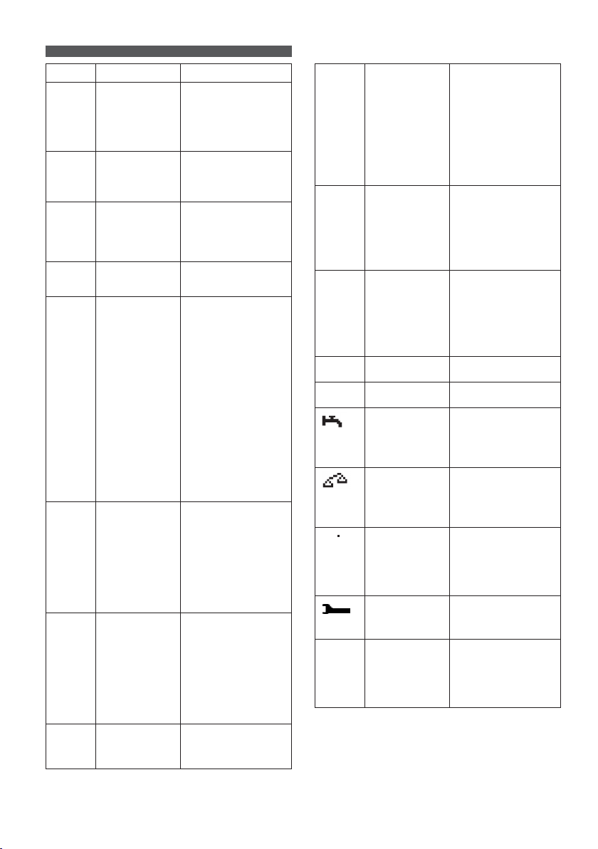
Fault
DF1*
DF2*
DF3*
DF4
DF5
DF PUMP
TH*
STOP*
Cause
Charger or mains
supply problem.
Output default.
Wrong battery.
Battery discharged
more than 80% of
its capacity.
Battery requires
inspection.
Fault in the air
circuit of the elec-
trolyte circulation
system.
Thermal problem
in charger resul-
ting in charge
interruption.
Critical battery
electrolyte level
Solution
DF1 appears when
the charger is not able
to supply its output
current. Follow the
breakdown procedure
for the charger, mains
voltage.
Check the correct
connection of the
battery (reversed
polarity cables) and
the output fuse.
Too high or too low
battery voltage. Battery
voltage must be within
the acceptable range.
Use proper charger for
battery.
Charge continues.
DF5 appears when the
charging profile has
been achieved with
a fault condition,
that can be a current
increase in regulation
phase demonstrating
a battery heating or a
badly programmed
regulation voltage, or
the charging time is too
long and has exceeded
the safety limit.
Check charging
parameters: profile,
temperature, capacity,
cables.
Check the battery
(defective cells, high
temperature, water
level..).
Check the proper
operation of the pump
via the menu
Option-
Option test
.
Check the air circuit
(pump, tubes).
If this fault occurs, the
charger will adapt the
battery charging profile
for an optimised charge.
Verify the proper
operation of the fans
and/or too high ambient
temperature, or wether
there is poor natural
ventilation to the
charger.
The charge process resu-
mes when the ambient
temperature decreases
below the correct value.
Top up battery electro-
lyte to the level speci-
fied in the battery
Instruction for Use.
BAT
TEMP*
DF MOD
WRG
MOD*
IQ SCAN
IQ LINK
T
NO
Wi-IQ
Critical battery
temperature.
One or more
modules are not
working correctly.
One or more
modules are
not the correct
specification.
Looking for
presence of Wi-IQ
Set the link
Wi-IQ-Charger
Low electrolyte
level
Default of balance
voltage detected
by the Wi-IQ
Too high battery
temperature.
Preventive
maintenance
indicator.
The Wi-IQ on the
battery is not func-
tioning correctly.
The charger will
charge the battery
with the default
setting.
Wait until the battery
temperature cools
down, check the battery
state (water, profile)
Verify the set up of
temperature in the
menu
Configuration-
Battery-High tempera-
ture
.
Check the temperature
sensor of the Wi-IQ®.
This fault will not
prevent the charger
from operating as long
as at least one module
is working correctly.
If all modules are not
working correctly, the
fault code displayed
will be DF1.
It could be due to a mix
of 24/36/48V and 72/80V
modules (not allowed)
or due to an incorrect
voltage setting in the
charger menu (eg
72/80V modules with
48V battery setting in
the menu)
Battery water topping
up required after
charging or check that
the Wi-IQ is functioning -
if in doubt, contact
EnerSys.
Check each battery
cell during discharge.
Check if the Wi-IQ is
properly adjusted, if in
doubt, contact EnerSys.
Verify the battery
electrolyte level or the
correct set up of the
charger.
Check the temperature
sensor of the Wi-IQ.
Consult a qualified
factory representative
to conduct preventive
maintenance operation.
Check if the Leds of the
Wi-IQ are flashing, if
yes, try to restart the
charge process, if not
or in doubt contact
EnerSys.
(*) : blocking fault preventing charging from continuing.
WARNING:
The electrical characteristics of the product are given according to its factory configuration. The user is responsible for any
modification to the product which may affect its characteristics.
03.2012
MESSAGES AND FAULT CODES
Table of contents
Other Hawker Batteries Charger manuals


