Hawker Lifetech User manual

Instructions for use Hawker Lifetech®Modular ENGLISH
SafEty INStructIoNS
aIM of tHIS MaNuaL
This manual is designed for use by any skilled worker wishing
to use Hawker Lifetech®Modular battery chargers for rechar-
ging lead/acid vented, (with or without electrolyte mixing),
valve regulated AGM and gel batteries.
This manual provides details of:
• Thechargers’functions.
• Anyadjustmentsrequiredandhowtousethechargers.
When producing this manual, EnerSys®has aimed to provide
its information in as simple and precise a manner as possible
but cannot assume any responsibility for any misinterpreta-
tion. The owner of the equipment is required to retain this
manual throughout the equipment’s life and to pass it on
to any purchaser in the event of its resale.
The manufacturer covers the guarantee in accordance with
the local regulations (contact local sales organization).
Recommended use
This manual should be read through carefully before using
the equipment and also read by anyone likely to use the
equipment.
Theequipment:
• Presentsnoobstaclestothefreecirculationofairthrough
the air inlet and outlet but, nevertheless, should be cleaned
ofdusteverysixmonthsbyaqualiedperson.
• Must be used in conformance with its indicated level of
protection and never come into contact with water.
• Must be used within the temperature limits stated in the
technical characteristics.
• Mustnotbeinstalledonsurfacessubjecttovibration(near
to compressors, engines, motors).
• Mustbeinstalledsothatthegasesfromthebatterybeing
charged, do not get sucked into the charger by its fan.
This appliance is not intended for use by persons (including
children) with reduced physical and mental capacities, who
are not experienced in their use, unless instructed to do so by
a person responsible for their safety.
Operator safety
Take all necessary precautions when the equipment will
be used in areas where there is the possible risk of an
accident occurring. Ensure appropriate ventilation accor-
ding to standard EN 62485-3 to allow any gases released to
escape. Never disconnect the battery while it is being charged.
ELEctrIcaL SafEty
The prevailing safety regulations must be observed. The sys-
tem protection installed on the power supply to the charger
must conform to the charger’s electrical characteristics. The
installation of a suitable circuit breaker is recommended. It is
imperative to ensure that when fuses are being replaced only
fuses of the specied type and of the correct are used. It is
strictly forbidden to use inappropriate fuses or to short-circuit
thefuseholders.ThisequipmentconformstoClass1safety
standards, which means that the appliance must be earthed
andrequirestobepoweredfromanearthedsupply.
Never open the equipment: High voltage could be still present
even turning off the charger.
Any adjustment, maintenance or repairs to the equipment
while it is open must only be carried out by an appropriately
skilled person who is aware of the risks involved.
Contact one of the company’s trained technicians if any prob-
lem is encountered when putting the charger into operation.
Thisequipmenthas beendesignedfor indooruse.It isonly
designed to recharge lead/acid batteries on industrial premises.
Whentheequipmentbecomesobsolete,thecasingsandthe
other internal components can be disposed of by specialist
companies. Local legislation takes precedence over any inst-
ructions in this document and must be scrupulously observed
(WEEE2002/96EC).
EnerSys reserves the right to make any improvements and/or
modicationstotheproductdescribedinthismanualatany
time and without prior notice and is not obliged under any
circumstances whatsoever to update the contents of this
manualnortheequipmentconcerned.
Theequipment’sproductionnumbermustbesuppliedwhen
requiringaservice.
If the charger is to be stored before its use, it must be
kept carefully sealed in its original packaging. It must be
stored in a clean and dry location at a moderate tempera-
ture (-20°C to +40°C). Equipment stored at a temperature of
less than 15°C must be brought progressively to operating
temperature (over a period of 24 hours) to avoid any risk of
condensation causing electrical faults (particularly short-
circuits).
Eu DEcLaratIoN
EnerSys hereby declares that the chargers in the
Lifetech Modular range covered by this declaration
conform to the descriptions laid down in:
• European Directive 2014/35/EU:
Low Voltage Directive
European Standard:
EN60950-1:2006+A11:2009+A12:2011+A1:2010+A2:2013
• European Directive 2014/30/EU:
ElectromagneticCompatibility
European Standards:
- EN61000-6-2:2006
- EN61000-6-4:2007+A1:2011
• European Directive 2011/65/EU:
ROHS
• European Directive 2013/35/EU:
Electromagneticelds
European Standards:
- EN62311:Oct2008
Note:DCcablesofthechargeremitlowpowermagneticelds
in their surroundings (<5cm). Even if emissions are below
the standard limits, people bearing medical implants should
avoid operating close to the charger during recharge.

PrESENtatIoN & uSE
INtroDuctIoN
The Lifetech®Modular range of chargers enable batteries to
be recharged from the mains supply. The microprocessor con-
trol automatically recognizes the battery’s voltage, capacity,
state of charge, etc., providing optimum battery control from
highlyefcientanalysesofitscondition.
1ph 3ph
12V
24V 24/36/48V
36/48V 72/80V
Several charging proles are available vented lead/acid
batteries: standard/Water Less®and heavy duty, electrolyte
circulation, valve-regulated: AGM and gel in a separate ver-
siondependingontheuser’sconguration.
Moreover, desulphation, equalizing and refreshing charges
are also integrated.
froNt PaNEL
Ref Button/LED Function Function
1Start/Stop button Start/Stop charge Cancelvalue(pressduring3s),
select of active menu
2 Greed LED Battery available
3 Yellow LED Battery in charge
4 Red LED Fault
5 Blue LED ACsupplyON(light) ACsupplyOFF(ACmissing)
6 Arrows Navigation buttons Return to top of list (press for 2 sec)
7 Equalizationbutton Startanequalization Access a sub menu
8 Esc Access a sub menu Closewindows
9LCDpanel Showsdetails(refertoLCDdisplaypar.)
10 USB port Download memories Uploadrmware
8
10 43 5
1
7
6
6
9
2
Single phase stand alone 1kW
Ref Function
1 ACinputcable
2DCoutputcable
3Cableholder
4 Ventilation openings
5LCDpanel
6 Navigation buttons
1
2
5 6
4
3

Phase 3 bay cabinet (2-3kW) & three phase
MEcHaNIcaL INStaLLatIoN
The charger can be wall or floor mounted. If wall mounted
make sure that the surface is free of vibrations and the char-
ger is mounted in a vertical position; if floor mounted make
sure that the surfaces are free of vibration, water, humidity.
You must avoid areas where the chargers may be splashed
with water.
Thechargermustbeheldby2or4xingssuitableforthetype
of support. The drilling pattern varies according to the model
of charger (please refer to the technical data sheet).
ELEctrIcaL coNNEctIoN
To the mains supply
You may only connect to the 1-phase 230Vac or 3-phase
400Vac mains supply (depending on the type of the charger)
by means of a standard socket and an appropriate circuit
breaker (not supplied). The current consumption is shown on
thecharger’sinformationplate.
To the battery
Polaritymustbeobserved.Anyreversalofpolaritywillblow
the output fuse, prevent charging and cause DF2 fault code to
bedisplayed.PleaserefertotheFaultmessagescodes.
Connection to battery
The charger must be connected to the battery by the cables
supplied:
• TheREDcable:tothebattery’sPOSITIVEterminal.
• TheBLACKcable:tothebattery’sNEGATIVEterminal.
Initiating charging
1. Connect the battery. If Default setting (autostart ON) then
the charge will start automatically else press the Start/
Stop button.
The display will show 3 different screens alternating
Completion of charging
1. The LCD screen will give you the message of availability
(AVAIL)
The battery is charged and ready to use.
2. STOP the charge and disconnect the battery.
To stop the charge press the Stop/Start button.
Never disconnect the battery during charge without stopping
the charging process.
This could lead to dangerous sparks or to charger damage.
3. Completion of charging with equalization
Manualequalizationonlyconcernsventedlead/acidbatteries.
It will be initiated manually or automatically by switch. All
othertechnologieswillhaveanautomaticpresetequalization
time.
To force manual equalization keep pressed the equalization
button (right button) and contemporary click the On/Off (only
chargingprolesforooded).Ifautomaticthenthescreenwill
also show the following message:
Ref Function
1 ACinputcable
2DCoutputcable,only
3 Option port
4 Ventilation openings
5LCDpanel
6 Navigation buttons
7 Cableholder(onlyonsinglephase)
1
3
2
56
4
Line1 Chargemode/chargingprole/
equalsymbol(ifselected)ornoblockingfault
Line 2 Chargingcurrent/totalvoltage/Ah+
Screen 1:
Line1 Chargemode/chargingprole/
equalsymbol(ifselected)ornoblockingfault
Line 2 Chargingcurrent/voltage/cell/chargingtime
Screen 2:
Line1 Chargemode/chargingprole/
equalsymbol(ifselected)ornoblockingfault
Line 2 Chargingcurrent/%stateofcharge/
estimated remaining time
Screen 3:
• Equalizationmodeauto
• Daysoftheweek(thesymbolbelowindicateswhenthe
equailzationisprogramed(e.g.SaturdayandSunday)
• Duringequalization
• Line1.modeequal
• Current/totalvoltage/remainingtime
1
3
2
5 6
4
7

4. Completion of charging with Float
If the oat function has been selected the screen will show
Themessageoating:
5. Completion of charging without equalization
The green ‘charging complete’ light is illuminated and
the message AVAIL is displayed. The display shows, in alter-
nation:
• Duringequalization
• Line1.modeoating
• Current/voltagepercell
• ThenumberofAhrecharged
Fault Cause Remedial action
No display and
blue LED off
No mains supply. Checkthepowersupplyandtheinputfuse(s).
DF CURRENT AppearsbeforeaDF1faultisdisplayed.
DF1* Chargerfault. Checkthepowersupplyvoltage.
DF2* Chargerfault. Checkthatthebatteryiscorrectlyconnected(thatthecablesare
not reversed) and check the output fuse.
DF3* Unsuitable battery. Batteryvoltagetoohighortoolow.Connectthecorrectbattery
to the charger.
DF4 The battery has been discharged more
than80%ofitscapacity.
Chargingcontinues.
DF5 Batteryrequiresinspection. DF5appearswhenthechargingprolehasbeenachievedwith
a fault condition, that can be a current increase in regulation phase
demonstratinga batteryheating ora badlyprogrammed regulation
voltage, or the charging time is too long and has exceeded the
safety limit. Check charging parameters (prole, temperature,
capacity,cables).Checkthebattery(defectivecells,hightempe-
rature, water level).
DF7 Pneumatic mixing air circuit fault (the
redlightashes).
Checktheaircircuit(pump,tubing).
TH* Thermal fault resulting in interruption of
charging.
Check that the fan(s) is (are) working correctly and/or that the
ambient temperature is not too high or whether there is poor
natural ventilation to the charger.
MOD TH Alternating with charge parameters -
one or more modules in thermal fault -
the charge process continues - the faulty
module(s) is (are) displayed + red led
ashing.
Check that the fan(s) is (are) working correctly and/or that the
ambient temperature is not too high or whether there is poor
natural ventilation to the charger.
If all modules are in thermal fault then a TH* fault will follow.
MOD DFC Alternating with charge parameters -
oneor moremodulesin DF1fault- the
charge process continues - the faulty
module(s) is (are) displayed + red led
ashing.
Checkpowersupply.
IfallmodulesareinDF1faultthenaDF1*faultwillfollow.
DEF ID Blocking fault - one or more modules
are not compatible with the charger
conguration (for example 24V charger
with one 48V module). This can happen
if the user replaces one module with
another one with a different voltage
setting.
Use correct module.
LcD fauLt MESSaGES coDES
(*) A blocking fault preventing charging from continuing.
PleasecontactEnerSys®Service.
Subject to technical modification without any prior notice. E&OE
www.enersys.com
06.2017
• Non-blockingfaultsifpresent
• Thechargingtimetaken.
Other Hawker Batteries Charger manuals

Hawker
Hawker MotionLine User manual
Hawker
Hawker MultiLine W0Wa User manual
Hawker
Hawker LIFESPEED MOD3 User manual
Hawker
Hawker EnerSys LifeSpeed IQ User manual
Hawker
Hawker MasterLine puls/EU User manual
Hawker
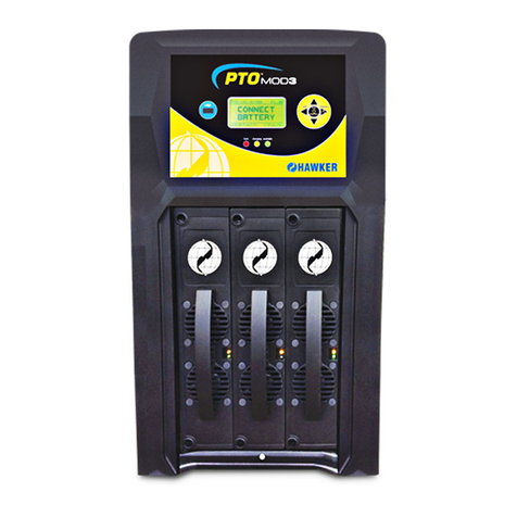
Hawker LIFEPLUS MOD3 Series User manual
Hawker
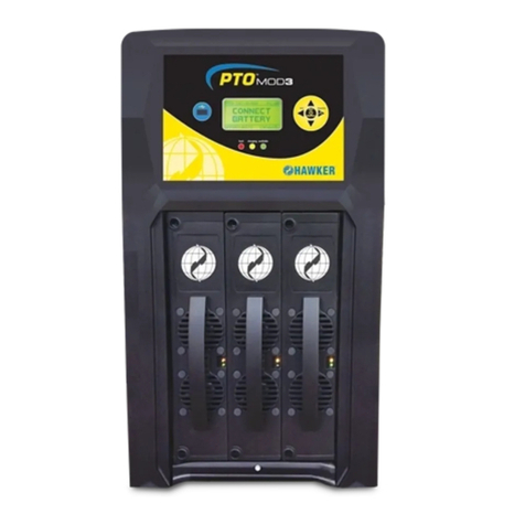
Hawker PTO MOD3 User manual

Hawker
Hawker Life IQ User manual


