Hawker LIFESPEED MOD3 User manual

For local parts, sales and service, call toll-free 1-800-251-6560.
AM-HLSM3-OM
Rev AB October 2019
Model:
S/N:
AC Input Voltage
Installed by
Date
IMPORTANT
Read and understand your user’s manual before installing, operating, or servicing this
product.
DO NOT DESTROY THIS BOOK
Battery Charger
with Wireless Communications
Owner’s Manual
LIFESPEED
MOD3
Models: LSM3 (Standard)
LSM3C (CEC)

LIFESPEED MOD3
Owner’s Manual
AM-HLSM3-OM
Rev AB October 2019
1
TABLE OF CONTENTS
Important Safety Instructions ............................3
Technical Information.........................................4
Part Number...................................................4
Cabinet Size/Gauge Letter Codes ..........4
AC Line Voltage Letter Codes.................4
Specialty Charger Options List................5
Serial No........................................................5
Battery Type...................................................5
Max AH..........................................................5
No. Cells ........................................................5
Max Modules..................................................5
Config Modules..............................................5
Hertz ..............................................................6
Phase.............................................................6
AC Volts.........................................................6
Config AC Amps.............................................6
Max AC Amps................................................6
Max DC Amps................................................6
DC Volts.........................................................6
Config DC Amps ............................................6
CEC ...............................................................6
cULus.............................................................6
Installation ...........................................................7
Location .........................................................7
Wall/Floor Mount Cabinet Chargers...............7
Electrical Connections....................................7
Connecting Input Power.................................7
AC Circuit Protection......................................7
Breaker/Fuse Chart ……………………………7
DC Plug Polarity.............................................8
Grounding the Charger ..................................8
Description of Operation ....................................9
General..........................................................9
Auto Start Charge ..........................................9
Charging Current............................................9
AC Power Fail................................................9
Series Charging .............................................9
Glossary...............................................................10
Battery Boss WC (BBWC™)..........................10
Block Out Time...............................................10
Charging Profile .............................................10
Cold Storage..................................................10
Equalization Charging....................................10
Gel Profile......................................................10
Float Charge ..................................................10
Ionic Profile....................................................10
OPPOR Profile...............................................10
Fast Charg ……………………………………...10
Refresh Charging...........................................11
Abbreviations and Acronyms ............................11
Operating Instructions........................................12
Control Panel .................................................13
Menu Access..................................................14
Idle Screen..............................................14
Main Menu Display .................................14
Main Menu..............................................14
System Setup ......................................................15
Date ...............................................................15
Time...............................................................15
Daylight Savings Time ………………………...15
Language.......................................................15
Displayed Units..............................................15
Energy Saver.................................................15
Display Brightness.........................................15
Network ………………………………………....15
Reset History …………………………………...15
Enter Password...................................................16
Change Password ………………………………....16
USB …………………………………………………..16
History Data ….………………………………...16
Save Setup Parameters ….………………..….17
Load Setup Parameters ……………………….17
Load Control Firmware ………………………..17
Load Module Firmware ………………………..17
Charge Profile Configuration ……………………17
Battery Capacity ……..………………………...17
Auto Capacity ……..…………………………...17
Battery Temperature ……..…………………...18
High Battery Temperature ……………………18
Restart Temperature ……..…………………...18
Charge Profile ……..…………………………..18
Ionic Charge Coefficient ……..……………....18
AGV Offset ……..………………………..........18
Constant Current Configuration ……………….18
Equalize Configuration …………………………..18
Equalize Days ……..…………………………..18
Equalize Time ……..…………………………..18
Equalize Duration ……..………………………18
Start Charge Configuration ……………………..19
Charge Delay …….………………..................19
Charge Blockout …………………..................19
Condition Charge %……………….................19
Opportunity Daily Charge .……….................19
Fast Voltage Regulation ……………………..19
Post Charge Configuration ……………………..19
Cool Down On/Off …….………………..........19
Cool Down Time …….…………....................19
Float On/Off …….………………....................20
Float Current …….………………..................20
Refresh On/Off …….………………...............20
Charger Configuration …………………………..20
Cabinet Bay Size …….………………............20
Number of Modules …….………………........20
Module Type …….………………...................20
72/80V Module Battery Voltage ....................20
DC Cable Setup …….………………..............20
Charger Options …….……………….............20
BBWC Communications …….……………….21
Electrovalve …….………………....................21
Enter Charger Serial Number …….…...........21
Customer Asset Number …….………….......21
Charging the Battery …………………………….22
Charger Idle Display …………………………22
Starting a Charge Cycle……………………...22
Delayed Start ………………………………....22
Count Down …………………………………..23
Charging Display ……………………………..24
End of Charge Display ……………………….25
Equalization ……………………………………25
Manual Equalize …………………………25
Automatic Equalize ……………………...25
Charger Information ……………………………...26

LIFESPEED MOD3
Owner’s Manual
AM-HLSM3-OM
Rev AB October 2019
2
Charger Serial #.............................................26
Asset #...........................................................26
Connects........................................................26
Complete Equalizes.......................................26
Complete Charges.........................................26
AH Returned ..................................................26
Faults.............................................................27
Modules................................................................28
Module Status Display ...................................28
Info........................................................................28
Module Information ……………………………28
Module LED Status..............................................28
Mounting Dimensions.........................................29
6 Bay Wall Mounting Dimensions...................29
12 Bay Wall Mounting Dimensions.................31
Maintenance and Service ...................................32
Component Locations ........................................33
Technical Specifications for 208/220/240V .......34
Technical Specifications for 440V .....................35
Technical Specifications for 480V .....................42
Technical Specifications for 600V .....................49
Maintenance Log.................................................53

LIFESPEED MOD3
Owner’s Manual
AM-HLSM3-OM
Rev AB October 2019
3
IMPORTANT SAFETY INSTRUCTIONS
WARNING: THE SHIPPING PALLET MUST BE REMOVED FOR PROPER AND SAFE OPERATION.
1. This manual contains important safety and operating instructions. Before using the battery charger, read all
instructions, CAUTIONs and WARNINGs on the battery charger, the battery and the product using the battery.
2. This battery charger is designed to charge flooded and sealed lead-acid batteries. Read and understand all
setup and operating instructions before using the battery charger to prevent damage to the battery and to the
charger.
3. Do not touch non-insulated parts of the output connector or the battery terminals to prevent electrical shock.
4. During charge, batteries produce hydrogen gas which can explode if ignited. Never smoke, use an open flame,
or create sparks in the vicinity of the battery. Ventilate well when the battery is in an enclosed space.
5. Do not connect or disconnect the battery plug while the battery is charging. Doing so will cause arcing and
burning of the connector resulting in charger damage or battery explosion.
6. Lead-acid batteries contain sulfuric acid which causes burns. Do not get in eyes, on skin, or on clothing. In
cases of contact with eyes, flush immediately with clean water for 15 minutes. Seek medical attention
immediately.
7. Only factory qualified personnel can service this equipment. De-energize all AC and DC power connections
before servicing the charger.
8. The charger is not for outdoor use.
9. Do not expose the charger to moisture. Operating conditions should be 32º to 113º F (0º to 45º C); 0 to 70%
relative humidity.
10. Do not operate the charger if it has been dropped, received a sharp hit, or otherwise damaged in any way.
11. For continued protection and to reduce the risk of fire, install chargers on a floor of non-combustible material
such as stone, brick, or grounded metal.

LIFESPEED MOD3
Owner’s Manual
AM-HLSM3-OM
Rev AB October 2019
4
TECHNICAL INFORMATION
There are two nameplates located on the outside of the charger and should be used to
check the application before installation. The “Main” nameplate includes the UL Model number
and the ratings of the cabinet at its full capacity, while the “Configured Ratings” nameplate
includes the Part number and the ratings of the cabinet as configured. The Configured Ratings
nameplate label must be replaced when adding or removing modules permanently in the field.
Part Number and UL Model Number
The UL Model Number specifies the characteristics of a full cabinet charger, while the Part
Number specifies the characteristics of the cabinet as configured, plus all options. The Part
Number is required in any discussion or correspondence regarding this unit.
LSM3 - 48F –240YR
Model type
Phase
(-) for Standard or (C) for CEC
Max DC Volts
Cabinet Size
Max DC Current @ Max DC V
Input Voltage Code
Options
Cabinet Size/Gauge Letter Codes
The following table describes the letter codes to be used in charger part numbers to
indicate the number of slots and size of DC cables.
Letter
Code
Module
Positions
Standard Cable
Gauge
Comments
F
6
3/0
Six slot, 3.5kW cabinet
L
12
3/0
12 slot, 3.5kW cabinet

LIFESPEED MOD3
Owner’s Manual
AM-HLSM3-OM
Rev AB October 2019
5
AC Line Voltage Letter Codes
The following table describes the letter codes used in the charger part number to indicate
the nominal AC line voltage(s) and frequency at which the charger is designed to operate.
Letter
Code
Voltage(s)
(volts rms)
Line
Frequency
(Hertz)
Comments
C
600
50/60
600 VAC only
G
208/220/240
50/60
208/220/240 VAC
H
440
50/60
440 VAC only
Y
480
50/60
480 VAC only
SPECIALTY CHARGER OPTIONS LIST
Suffix
Description
1
15 Ft of DC cable.
2
20 Ft of DC cable.
3
25 Ft of DC cable.
4
30 Ft of DC cable.
E
LAN (Ethernet Compatible)
F
Red/Green Next Battery Capable –used in conjunction with
BSI and BSS
R
Remote control capable ( order remote control separately)
V
PLC capable
Serial No.
This is the serial number that indicates complete information about the charger. It must be
supplied with the part number on any correspondence or discussion regarding this charger.
Battery Type
The chemical content of the battery this charger is designed to charge:
L-A = Lead Acid.
Max AH
This number indicates the maximum Amperes-Hours (AH) capacity of this charger. Charging
batteries of AH capacities not specified here will cause the charger to deviate from the
specifications.
No. Cells
This is the number of cells this charger is designed to charge.
Max Modules
This is the maximum number of power modules that can be installed into the charger cabinet.
Config Modules
This is the actual number of power modules installed in the charger cabinet.

LIFESPEED MOD3
Owner’s Manual
AM-HLSM3-OM
Rev AB October 2019
6
Hertz
This is the frequency in cycles per second of the AC input voltage this charger is designed to
operate on. Do not operate charger at a different frequency or from a generator with unstable
frequency.
Phase
Number "1" indicates a Single Phase Charger and number “3” indicates a Three Phase Charger.
AC Volts
This is the input voltage accommodated by this charger.
Failure to use the correct voltage will result in damage to the charger and/or the battery.
IMPORTANT: THE CHARGER WILL OPERATE ONLY ON NOMINAL AC LINE VOLTAGES
INDICATED ON THE NAMEPLATE.
Config AC Amps
This is the AC current that this charger will draw with the number of power modules shown in
Config Modules on the nameplate.
Max AC Amps
This is the Maximum AC current this charger will draw from AC power. This charger must be
connected to a branch circuit protection in accordance with the National Electrical Code
NFPA70 and local codes. (AC breaker/fuse values can be found on a decal outside the
charger.)
Max DC Amps
This is the maximum DC current that this charger cabinet will deliver to a discharged battery
when fully populated with power modules.
DC Volts
This is the rated DC output voltage of the charger.
Config DC Amps
This is the DC current that this charger will deliver to a discharged battery with the originally-
furnished (Config Modules) number of power modules.
CEC
This logo is applied to chargers that are certified with the California Energy Commission in
compliance with Appliance Efficiency Regulations:
cULus
This logo is applied to chargers that have been tested to applicable standards and requirements
by Underwriters Laboratories (UL) and the Canadian Standards Association (CSA):

LIFESPEED MOD3
Owner’s Manual
AM-HLSM3-OM
Rev AB October 2019
7
INSTALLATION
WARNING: THE SHIPPING PALLET MUST BE REMOVED FOR PROPER AND SAFE
OPERATION
Location
For maximum trouble-free service, choose a location which is free of excess moisture, dust and
corrosive fumes. Also, avoid locations where temperatures are high or where liquids will drip on
the charger. Follow charger warning label when mounting on or over a combustible surface. Do
not obstruct the ventilating openings.
Wall/Floor Mount Cabinet Chargers
The charger must be permanently mounted in a vertical position. The lower part of the charger
must be at least 12 inches from the charger below if installed above another charger, and the
upper part 12 inches from the ceiling. The distance between two chargers must be no less than
12 inches. Use the mounting kit supplied with the charger. See the Mounting Dimensions section
at the end of this manual for proper Wall and Floor mounting.
NOTE: Ambient temperature cannot exceed 113° F (45° C).
Electrical Connections
To prevent failure of the charger, be sure it is connected to the correct line voltage.
WARNING: MAKE SURE THE POWER TO THE CHARGER IS OFF AND THE BATTERY IS
DISCONNECTED BEFORE CONNECTING THE INPUT POWER TO THE TERMINALS OF
THE CHARGER.
Connecting Input Power
Connect the input power to the appropriate terminals, including ground. For screw type
terminals, torque to 15 in.lbs. Follow your local and National Electric Code in making these
connections.
AC Circuit Protection
The user must provide suitable branch circuit protection and a disconnect method from the AC
power supply to the charger to allow for safe servicing.
Breaker/Fuse Chart
AC Amps
(A)
Breaker/Fuse size
(A)
1 - 12
15
12.1 - 16
20
16.1 - 20
25

LIFESPEED MOD3
Owner’s Manual
AM-HLSM3-OM
Rev AB October 2019
8
20.1 - 24
30
24.1 -28
35
28.1 - 32
40
32.1 - 36
45
36.1 - 40
50
40.1 - 48
60
48.1 - 56
70
56.1 - 64
80
64.1 - 72
90
72.1 - 80
100
80.1 - 88
110
88.1 - 100
125
DC Plug Polarity
The charging cables are connected to the DC output of the charger with the red cable to the
positive bus bar, and the black cable to the negative bus bar. The red cable is terminated into
the “+” side of the battery connector, and the black cable is terminated into the “-“side of the
connector. The output polarity of the charger must be observed when connecting to the battery.
Improper connection will open the DC fuses in the power modules.
DANGER: FAILURE TO GROUND THE CHARGER COULD LEAD TO FATAL ELECTRIC
SHOCK. Follow local and National Electric Code for ground wire sizing.
Grounding the Charger
Connect incoming grounding conductor to the ground lug provided on the charger support panel.
Torque the Ground wire to 15 in.lbs. This lug is marked as shown:

LIFESPEED MOD3
Owner’s Manual
AM-HLSM3-OM
Rev AB October 2019
9
DESCRIPTION OF OPERATION
General
The LIFESPEED MOD3 series of chargers are compatible with batteries at 24, 36, 48 volts or
72, 80 volts, depending on model.
Battery recognition (voltage, capacity, state of charge, temperature, etc.) is accomplished by
wireless communication from the Battery Boss®. Battery management is optimized through
use of the Battery Boss®. Three charging profiles are available based on the configuration
chosen by the operator. Furthermore, desulfation, equalization and compensation charges are
integrated.
Auto Start Charge
When a battery is connected to the charger, the control board senses the voltage and after a 20
second delay, the charger starts charging the battery automatically.
Charging Current
Charging current is determined by the charger based on battery voltage and its state of charge.
Charging current declines automatically as battery voltage rises during the charge. As the battery
charges, the graphical LCD display will output various charge parameters including the charging
current.
AC Power Fail
If the AC power fails with a battery connected to the charger during a charge cycle, the charger
will reset and start a new charge cycle when power is restored. All charger settings as well as
the time and date are preserved.
Series Charging
In series charging, the voltages of both batteries add up and must match charger’s nameplate
rating. The charger’s amp-hour rating must be equal to each of the batteries’ amp-hour rating.
Charge cycle will not start unless both batteries are connected.

LIFESPEED MOD3
Owner’s Manual
AM-HLSM3-OM
Rev AB October 2019
10
GLOSSARY
Battery Boss WC (BBWC™)
This is a compact wireless electronic device that is installed on the battery to provide real-time
battery diagnostics. The device monitors the battery parameters such as capacity,
temperature, voltage and state of charge, allowing the user to maximize battery performance
and life.
Blockout Time
This function prevents the charger from charging the battery during the block out time window.
If a charge cycle has started before the block out window it is inhibited during the block out
window and will automatically restart the charge cycle at the end of the block out window.
Charging Profile
The charging profile defines the rate of current charge over time. The charger adapts to the
battery’s condition and level of discharge.
Cold Storage
This is a charging profile that allows the configuration of the charger for use with batteries in cold
storage application. The profile is an IEI (constant current, constant voltage, constant current)
type with a number of user configurable parameters.
Equalization Charging
Equalization charging is performed after normal charging. It balances the electrolyte densities in
the battery’s cells.
Float Charge
A float charge at the end of standard charge is intended to compensate for consumption by the
truck electronics that are left on when truck is not being operated.
Ionic Profile
Also called “ionic mixing”, this type of charging profile consists of sending short pulses of current
to stimulate gas formation in the active material, causing sulfuric acid to be distributed outside
the plates. This system of mixing the electrolyte enables more rapid charging of flooded cell
batteries subject to very high demands and balances out differences in density, homogenizing
the electrolyte across the surface of the plates.
Opportunity Profile
The OPPOR charge profile is used when opportunity charging is desired. It has a start rate of
25% of the batteries rated amp hour capacity, requires one complete recharge in every 24 hours
of service and must have an equalize charge done once a week which is programmed to run
automatically.
Operation:
During opportunity charging the user can plug the battery in and charge it during breaks,
lunch or any work stoppage time. One time per day the battery must receive a full
standard Ionic recharge. The charger real time clock must be adjusted and set for this
switch in charging profile to occur automatically at a predetermined time. Sufficient time
should be scheduled after the full charge to allow the batteryto completely cool to ambient
temperatures before use.

LIFESPEED MOD3
Owner’s Manual
AM-HLSM3-OM
Rev AB October 2019
11
Note: The user must configure the charger for the time of day that the full recharge is to
take place, they must also configure the day of the week that the equalize charge will take
place.
Fast Charge Profile
Utilizing a patented algorithm, the electronic circuits of the LifeSpeed charger reduce the
natural resistance of the battery by introducing short discharge cycles into the charging profile.
This homogenization of the ions around the plates allows for a better distribution of the active
ions in the charging zones. Therefore, a substantially larger current can be applied and
sustained, resulting in a much faster charging process while maintaining full temperature
control during the charge.
Refresh Charging
Refresh or maintenance charging enables the battery to be maintained at maximum charge all
the time that it is connected to the charger. Refresh charge is applied at a predetermined
intervals after charge is complete and battery remains connected to charger.
ABBREVIATIONS AND ACRONYMS
AH Amp-Hour
AWG American Wire Gauge
AVAIL Available
BBWC™ Battery Boss Wireless Connection
CEC California Energy Commission
DoD Depth of Discharge
GND Ground
kW Kilowatt
L-A Lead Acid
RFI Radio Frequency Interface
LCD Liquid Crystal Display
LED Light Emitting Diode
TFT Thin Film Transistor
USB Universal Serial Bus

LIFESPEED MOD3
Owner’s Manual
AM-HLSM3-OM
Rev AB October 2019
12
OPERATING INSTRUCTIONS
The LIFESPEED MOD3 series of chargers are compatible with batteries at 24, 36, 48 and 72 or
80 volts (depending on the version supplied).
Battery recognition (voltage, capacity and state of charge) is accomplished automatically by the
microprocessor. Several charging profiles are available (Fast, Opportunity, Ionic) based on the
configuration chosen by the operator. Furthermore, equalization and compensation charges are
integrated.
The LIFESPEED MOD3 includes an adapter to communicate to a BBWC™. The BBWC™ is an
advanced battery module that measures, tracks and stores important battery parameters such
as temperature, electrolyte level, voltage and AH throughput. This data is wirelessly transmitted
to the LIFESPEED MOD3 to optimize charging, alert the operator to battery issues and
safeguard the battery from being permanently damaged.
LIFESPEED MOD3
Owner’s Manual
AM-HLSM3-OM
Rev AB October 2019
13
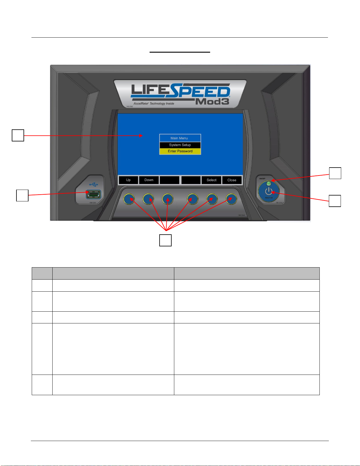
CONTROL PANEL
Ref
Function
Description
1.
Graphical TFT LCD Display
Displays charger operation info and Menus
2.
Navigation buttons
Each navigation button corresponds with the
rectangle located directly above it
3.
STOP and START button
Stop and restart battery charge
4.
LED indicator
Solid RED, fault indicator
Blinking RED, charge stopped
Solid YELLOW, charging
Solid GREEN, charger idle
Blinking GREEN, charge complete
5.
USB port
Logs charge data, updates firmware and
saves setup parameters
1
5
2
3
4

LIFESPEED MOD3
Owner’s Manual
AM-HLSM3-OM
Rev AB October 2019
14
Menu Access
Idle Screen
When the charger is idle, select Setup, the Main Menu is then displayed. The main menu is
automatically exited after 120 seconds of inactivity or can be exited voluntarily by pressing the
Close button.
Main Menu Display
Main Menu
All menus are accessed from Main Menu. The menus that require a password are not displayed
until the correct password has been entered.
1. Select a menu option using the Up/Down navigation buttons.
2. Display the highlighted menu screen by pressing the Select navigation button.
3. Return to the main menu by pressing the Close button.
System Setup

LIFESPEED MOD3
Owner’s Manual
AM-HLSM3-OM
Rev AB October 2019
15
Enter Password
System Setup
Date
Sets the date of the charger (MM/DD/YY).
Time
Sets the time of the charger (24 Hr Clock).
Daylight Savings Time
Enables or disables automatic clock adjustment for daylight savings time. When enabled, time
will move ahead one hour at 02:00 on the second Sunday in March and will move back one
hour at 02:00 on the first Sunday of November. The charger must be powered up at the time of
the change for it to take affect.
Language
Selects the language displayed in the menus.
Displayed Units
Selects metric (EU) or imperial (US) units for temperature, length and size of DC cables.
Energy Saver
Enables or disables energy saver mode. When enabled, if the charger is left in idle mode for
5 minutes, the display backlight and power modules will shut off to save energy.
Display Brightness
Adjusts the brightness of the display screen.
Network
This can only be accessed by entering a password. If you don’t know the password then a
service technician will need to set this up.
Type: Wired, Wireless: Select network type
Charger IP Address: Enter address
Subnet Mask: Enter Subnet Mask
Gateway Address: Enter Gateway Address
Wireless Settings: Set SSID, Security, and Passphrase
Modbus: Enable or Disable Modbus
Transceiver Address: Enter address
Reset History
This can only be accessed by entering a password. If you don’t know the password then a
service technician will need to clear history.
Select Yes to delete all history or No to exit without deleting history

LIFESPEED MOD3
Owner’s Manual
AM-HLSM3-OM
Rev AB October 2019
16
Enter Password
This is where the password is entered to gain access to service level menus by an authorized
Hawker service personnel only. Some of the items are accessible by all service personnel,
others are only accessible through a higher level password controlled by the individual dealer’s
service manager.
1. Use the Up/Down buttons to select the correct alphanumeric character.
2. Use the Left/Right buttons to move the cursor either left or right.
3. Once the correct password is entered press the Select button.
If the correct password is entered, the display will automatically jump to the main menu with the service level
menu displayed.
System Setup
Enter Password
Change Password
USB
Charge Profile Configuration
Constant Current Configuration
Equalize Configuration
Start Charge Configuration
Post Charge Configuration
Charger Configuration
erord
Change Password
This can only be accessed by entering the admin password. If you don’t know the admin
password then you will not be able to change any passwords.
Change Tech Password Use this to change the main password
Change Admin Password Use this to change the admin password
erord
USB
History Data
Enables the storage of charge History Data to a USB data storage device (aka memory stick, thumb drive).
To save charge history data:
1. Insert the data storage device in the USB port on the front of the charger.
2. Go to Setup->USB->History Data.
3. Select Filter History Data and set the number of days (30, 60, 90, 180, 360, All) Defaults to all if no
filter is selected.
4. Select Save Memo History Data to create a file to save History Memo Data. Default filename is
the charger serial number. Use the Up/Down buttons to change the alphanumeric character
and the Right/Left buttons to move the cursor. When you have entered the desired file name
press save.
5. Remove data storage device from USB port. The file, in CSV format will be stored in the data storage
device.

LIFESPEED MOD3
Owner’s Manual
AM-HLSM3-OM
Rev AB October 2019
17
Save Setup Parameters
Enables the storage of the charger Setup Parameters to a USB data storage device (aka memory stick, thumb
drive).
Load Setup Parameters
Enables the uploading of the charger Setup Parameters from a USB data storage device (aka memory stick,
thumb drive).
Load Control Firmware
Enables the updating of the charger’s internal firmware. Firmware updates will be provided by Hawker.
Load Module Firmware
Enables the updating of the power modules’ internal firmware. Firmware updates will be provided by Hawker.
erord
Charge Profile Configuration
Battery Capacity
Without BBWC: this adjusts the battery AH capacity used by the charger to determine start and finish
rates, and should match the AH capacity of the battery being charged.
With BBWC: the battery AH capacity will be automatically transmitted from the BBWC.
When running in ionic: In ionic with Auto Capacity is enabled, the value is not used and it automatically
calculates the Ah capacity of the battery. If using ionic and Auto Capacity is disabled the charger will use this for
the Ah capacity of the battery.
Auto Capacity
Select either Disable or Enable. Only used for ionic. All other profiles are manual all the time and will either
use the battery Ah programmed into Battery Capacity or the value the charger reads from the BBWC. When
enabled in ionic the charger will automatically adjust to battery Ah sizes within the range it covers. (depending
on number of modules installed)
Battery Temperature
This parameter adjusts the regulation voltages on the charging profile (values between 5° and 149° F (–15°
and 65° C).
Without BBWC: defines the average operating battery temperature before the charge. It is recommended
the average electrolyte temperature be entered, especially in cold areas.
With BBWC: the battery operating temperature will be automatically transmitted from the BBWC. The
battery temperature will be analyzed during the charge; if it increases too much, the charger will stop to prevent
any possible damage.
High Battery Temperature
Defines a battery temperature safety limit.
Without BBWC: not used.
With BBWC: If the battery temperature, during the charge, reaches the programmed limit, the charger will
stop the charge cycle and wait until the temperature decreases.

LIFESPEED MOD3
Owner’s Manual
AM-HLSM3-OM
Rev AB October 2019
18
Restart Temperature
Without BBWC: not used.
With BBWC: Defines the temperature at which the charge will restart, if the programmed limit is reached, and
the charge stops.
Charge Profile
Select Fast, Opportunity, or Ionic. This setting will be overridden by the BBWC programming
so make sure the BBWC is set to tell the charger the profile you desire the charger to run.
Ionic Charge Coefficient
This is only accessible through high level password.
If you do have access to this setting make sure you understand what you are doing. If adjusted incorrectly it
could eventually damage a battery if not corrected.
This is the amount of overcharge built into the Ionic charge profile to compensate for losses in the battery
during recharge. (factory set to 15%, means total of 115%)
AGV_offset
For AGV applications, enter amount of Amps onboard electronics draw during charging. Allowed range is 0 to
20A. Entering 0 disables
erord
Constant Current Configuration
Caution: This mode is for use by trained service technicians only. For instructions on use see
charger service manual.
erord
Equalize Configuration
Equalize Days
Select day or days of the week to equalize the battery. You may select none, or as many days as you need.
Equalize Time
Equalize Time of Day: Sets the time of day the Equalize charge will start (24hr clock).
Equalize Delay: Sets the delay between the normal charge and the equalization charge from 0 to 24 hrs.
Equalize Duration
Sets the equalization time from 00:01 to 23:59. (hh:mm)
erord

LIFESPEED MOD3
Owner’s Manual
AM-HLSM3-OM
Rev AB October 2019
19
Start Charge Configuration
Charge Delay
Charge Delay Type:
- OFF (no delay)
- Charge Delay Time of Day
- Time After Battery Connect
Charge Delay On Days: Selects day or days of the week to delay charge. One or more days may be
selected, or none.
Charge Delay Time of Day: Charge will not start until the time of day stored in VALUE (24 Hour format) is
reached.
Delay Time After Battery Connection: Start of charge is delayed by the amount of time stored in
VALUE (0 to 24 Hours).
Charge Blockout
Blockout Days: Selects day or days of the week to block out charge. One or more days may be selected,
or none.
Blockout Start Time: Sets block out start time.
Blockout End Time: Sets block out end time.
Conditional Charge %
Set conditional charge %. The charger will only charge if the battery has reached the limit of depth of
discharge (DoD) of more than x%. For example if the user wants to charge the battery only if it is discharged
more than 30%, the parameter 30 has to be entered in the conditional charge. The 0 value disables the
function.
Opportunity Daily Charge
Start Daily Charge Time: Sets daily charge start time.
End Daily Charge Time: Sets daily charge end time.
Fast Voltage Regulation
This is only accessible through high level password. If you do have access to this setting make sure you
understand what you are doing. If adjusted incorrectly it could eventually damage a battery if not corrected.
Enter value between 2450 and 2750 in mVPC. Usually not
necessary to change. Factory default is 2650.
erord
Post Charge Configuration
Cool Down ON/OFF
Turns the cool down ON or OFF.
Cool Down Time
Sets the period of cool down time.
This manual suits for next models
2
Table of contents
Other Hawker Batteries Charger manuals

Hawker
Hawker Life IQ User manual

Hawker
Hawker Lifetech User manual

Hawker
Hawker EnerSys LifeSpeed IQ User manual

Hawker
Hawker MultiLine W0Wa User manual

Hawker
Hawker MotionLine User manual

Hawker
Hawker PTO MOD3 User manual

Hawker
Hawker LIFEPLUS MOD3 Series User manual

Hawker
Hawker MasterLine puls/EU User manual


