ADVANSEA Speed s400 User manual

SPEED S400
User manual
Manuel utilisateur
Other languages available on the CD-Rom or at :
Autres langues disponibles sur CD-Rom ou sur:
www.advansea.com

S400 advanSea instruments comply with regulations in force.
Important
It is the owner’s sole responsibility to ensure that this appliance is installed and used in
such a way that will not cause any accidents, personal injury or property damage. The
user of this appliance is solely responsible for observing safe boating practices.
Installation: if not installed correctly, the appliance will not operate to the best of its
ability. In the event of doubt, please contact your advanSea retailer. Ensure that all
holes made to mount the appliance are drilled in places without risk and that they do
not weaken the structure of the boat. If in doubt, contact a qualified boat builder.
PLASTIMO SHALL NOT BE HELD LIABLE IN THE EVENT THE USE OF THIS APPLIANCE
CAUSES ACCIDENTS, DAMAGE OR INFRINGEMENT OF THE LAW.
Reference language: this statement, instruction and user manuals and other
information documents regarding the appliance, hereinafter referred to as
"documentation", may be translated into other languages. In the event of a dispute
regarding interpretation of the documentation, the French version shall be binding.
This manual presents the procedures for installing and operating the appliance at the
date of printing. AdvanSea reserves the right to modify the technical characteristics of
the appliance without notice.
Copyright © 2009 Plastimo, France, all rights reserved. AdvanSeaTM is a
registered trademark of Plastimo.
Warnin
g

Installation and Operation Manual S400 series 2
1. Introduction
1.1. General presentation ........................................ p.4
1.2. Components supplied with your Speed S400 ...... p.5
1.3. Technical characteristics ................................... p.5
2. General operation
2.1. Powering on..................................................... p.7
2.2. Operation in normal mode ................................ p.7
2.2.1. Selecting information on the display
2.2.2. Selecting units of measurement
2.2.3. Resetting data
2.2.4. Countdown timer
2.2.5. Backlighting
2.3. Alarms ............................................................. p.9
2.3.1. Setting the speed alarm thresholds
2.3.2. Setting the battery alarm threshold
2.4. Configuration.................................................... p.11
2.4.1. Speed damping
2.4.2. Calibrating the water temperature
2.4.3. Calibrating by speed
2.4.4. Calibrating by log
2.4.5. Configuring the countdown timer
2.4.6. Simulation mode
2.4.7. Key beeps
2.4.8. Resetting data in the memory
2.5. Standby ........................................................... p.16
2.6. Network operation (Bus AS-1) ........................... p.16
2.7.1. Displaying multiple data
2.7.2. Remote access
2.7. Messages......................................................... p.17
3. Installation
3.1. NMEA 0183 interfacing...................................... p.18
3.1.1. NMEA 0183 input interface
3.1.2. NMEA 0183 output interface
3.2. Mounting and connections................................. p.19
3.2.1. Mounting the Speed S400 unit
Table of contents

Installation and Operation Manual S400 series 3
3.2.2. Description of electrical connections
3.2.2.1. Bus connection
3.2.2.2. Speed connection
3.2.3. Connections
4. Troubleshooting ...................................... p.22

Installation and Operation Manual S400 series 4
Thank you for choosing an AdvanSea product. We are convinced your S400 instrument
will provide you with many safe and happy years of navigation. This manual describes
how to install and operate the Speed S400 AdvanSea.
1.1. General presentation
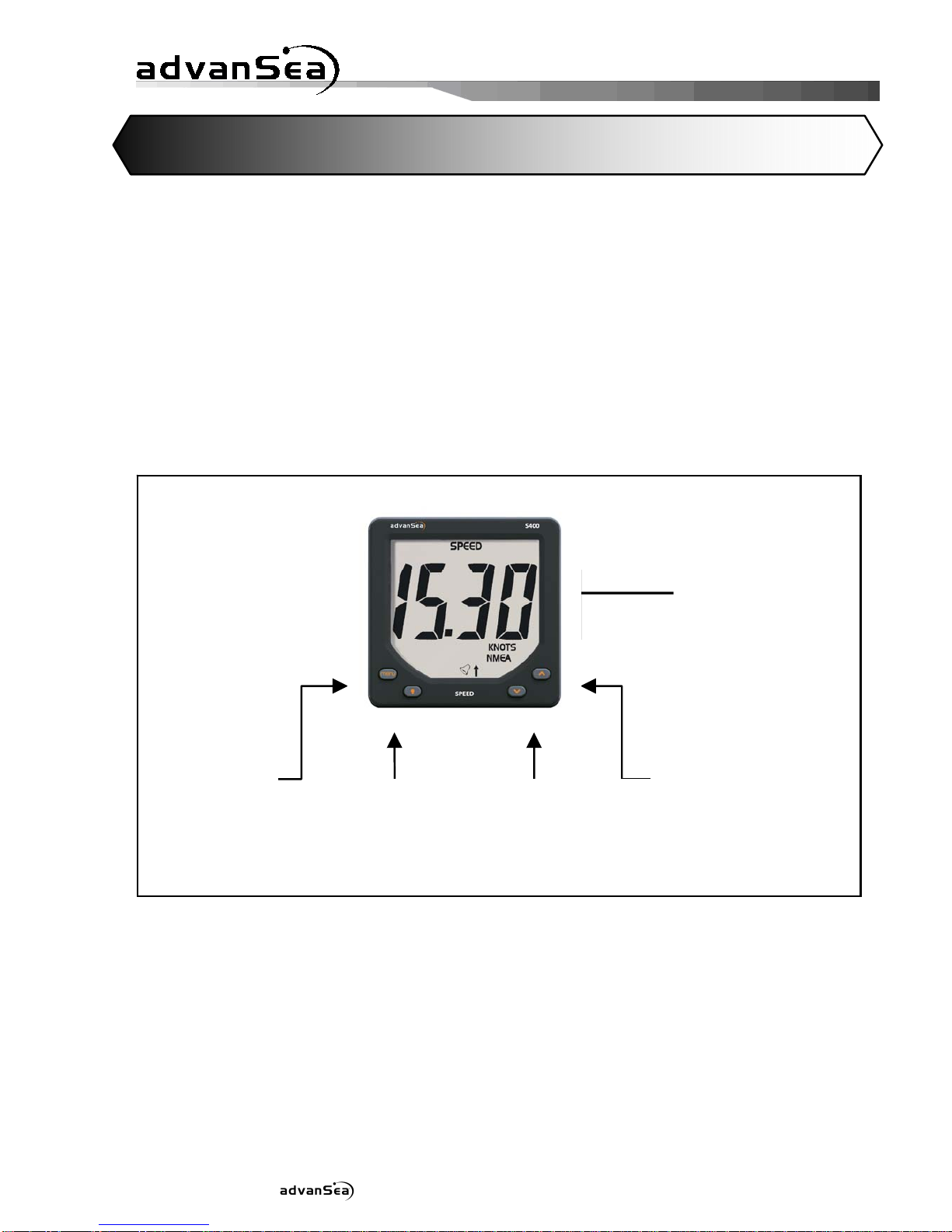
Description of the display:
The S400 unit is equipped with a large screen, and large characters for optimum
readability from all angles of vision. The screen is treated against condensation to
prevent the formation of mist. The screen and its keys are backlit with adjustable level.
The LCD screen on your Speed S400 is designed to:
•display the surface speed of the boat
•display the water temperature
•display the battery voltage
•acquire data through its NMEA input
•send data via its NMEA output
•exchange data on the AS-1 AdvanSea bus
•activate external lights and buzzers
- Backlighting
setup
- Validation
- Standb
y
-Decrease
- Change units
- Increase
- Change units
- Menus
alarms and
configuration
Giant display
(
45mm characters
)
1 Introduction

Installation and Operation Manual S400 series 5
To do so, it is supplied with 2 connection cables:
•1 connector-free cable for the power supply, the bus, the NMEA IN & OUT, the alarm
output
•1 LT8 cable for connection to the speedometer sensor
The Speed S400 is part of the S400 advanSea family of navigation instruments,
including instruments for measuring speed, depth, and wind. They may be connected
together to form an integrated data system for a boat (see chapter 2.6).
1.2. Components supplied with your Speed
S400
The Speed S400 comes with (as standard):
-protective cover
-user manual
-warranty card
-adhesive rear sealing joint for flush mounting
The Speedi S400 does not come with sensors. You can order complete kits, or
consult our website www.advanSea.com.
You will also find a complete list of accessories at www.advanSea.com
1.3. Technical characteristics
Measurement characteristics
Speed:
Measurement range: from 0.0 to 60.0 knots
Speed ratio: fixed at 6.1 Hz/knots
Accuracy: ±1.0 knots up to 20.0 knots and ±5% beyond 20.0
knots.
Resolution: 0.01 from 0 to 19.99 and 0.1 beyond
Calibration possible on 2 measurement points (Slope and Offset)
Trip log:
Measurement range: from 0.00 to 655.35 kilometres
Resolution: 0.01
Total log:
Measurement range: from 0 to 65535 kilometres
Resolution: 1
Battery voltage:
Measurement range: from 10.0V to 16.5V
Accuracy: ±0.2V
Resolution: 0.1V

Installation and Operation Manual S400 series 6
Electrical specifications
Buzzer output
(green wire):
Switched to ground, open collector, 30 V DC and 300 mA max.
It is recommended to protect this output with a 300 mA fuse.
NMEA 0183:
Version 3.01, asynchronous 4800 baud, 8 bit link, without
parity, 1 stop bit. The electrical levels used on the NMEA output
are referenced to the ground and vary according to the system’s
voltage supply.
On powering on, a proprietary NMEA frame $PNKEV,
SPEEDV1.00*44
is sent to identify the transmitter.
Communication
bus:
Half-Duplex 38400 baud link on one wire. Words are sent on 8
bits, without parity with 1 stop bit. The number of devices
connected to the bus is limited to 20.
Power supply:
9 volts to 16.5 volts / Consumption <150m
Mechanical specifications
Overall
dimensions
Unit size 112mm x 112mm depth 28mm
Mounting on flat wall by means of a threaded drum of diameter
49mm, step 1.5mm and length 35mm and a plastic nut diameter
80 mm
Environment
IP66 Front panel
IP40 rear panel
Operating
temperature
From -10°C to +50°C
Storage
temperature
From -20°C to +60°C

Installation and Operation Manual S400 series 7
2.1. Powering on
The SPEED S400 display does not include an integrated switch. The unit is powered by
a 12 V DC supply on the red (+) and black (-) wires. When stopped, all settings are
memorized.
2.2. Operation in normal mode
2.2.1. Selecting information on the display
The and keys are used to select various data in the display.
Key operation:
2 General operation
Water temperature
TEMP*
CHRONO*
Regatta Stopwatch
Battery voltage
BAT*
SOG*
Speed over ground
SPEED*
Boat Speed
AVG SPEED*
Average speed
MAX SPEED*
Max speed
LOG*
Trip log
Total log
TOTAL LOG*
*Information displayed on the LCD

Installation and Operation Manual S400 series 8
2.2.2. Selecting units of measurement
To change the unit of measurement for some data, press at least 2 seconds on the
or key.
The following table summarizes the various units displayed according to the data
selected:
In bold, default units.
2.2.3. Resetting data
To reset the average speed and max speed data on the upper line, first display the
parameter to be reset to 0 and press simultaneously at least 2 seconds on the +
keys.
To reset the average speed, max speed, Trip log and Total log data on the lower line,
first display the parameter to be reset to 0 and press simultaneously at least 2 seconds
on the + keys.
Data LCD label Units
Water temperature TEMP °F °C
Timer CHRONO
Battery voltage BAT V
Speed over ground SOG
Surface speed SPEED
Average speed AVG SPEED
Max speed MAX SPEED
KNOTS KPH MPH
Trip log LOG
Total log TOTAL LOG NM KM

Installation and Operation Manual S400 series 9
2.2.4. Countdown timer
Once CHRONO is displayed, trigger it by pressing simultaneously on the +
keys.
The countdown starts from the data displayed (which can be configured between 1
and 10 minutes, see menu paragraph 2.5.6.). A long beep signals when the
countdown switches to the full minute. The end of the countdown is signalled by a
short beep every second for the last 5 seconds followed by a long beep to mark the
end of the countdown.
When the countdown is finished, the countdown timer counts the navigation time in
hours/minutes (with two points flashing per second).
Press again simultaneously for at least 2 seconds on the + keys during the
countdown to stop it and reset the display to the selected value.
2.2.5. Backlighting
The display and the 4 keys are backlit, with 4 levels of intensity. Level "0" corresponds
to backlighting switched off.
To control backlighting:
Press the key to display the backlighting page, then the
and keys to adjust the lighting level from 0 to 4.
Pressing again on the key send the lighting level on the
bus to control backlighting on other device displays.
2.3. Alarms
The icon is lit when at least one alarm has occurred on one item of data managed
by the SPEED display. A sensor alarm appears when it is activated (different from 0)
and the measurement has exceeded the high or low threshold previously defined. This
alarm is then shown by:
•The flashing icon
•The data concerned by the alarm flashing,
•Automatic lighting of the LCD backlighting to its highest level,

Installation and Operation Manual S400 series 10
•The internal buzzer sounds,
•The buzzer or the external lights are activated.
An alarm can be cancelled and inhibited for 3 minutes by pressing on any key on the
keypad. After this period, a new alarm may be triggered when the measurement
sensor once again exceeds the programmed thresholds.
Several devices interconnected on the bus, can be used to relay a sensor alarm to
other compatible displays present on the network. Example: a boat speed alarm can
be viewed on all "SPEED" displays present on board.
The Boat speed data can be monitored by configuring high and low alarm thresholds.
The Battery voltage data can be monitored by configuring the low threshold alarm.
When selecting an alarm, the SPEED unit will alternatively display the alarm name and
its current value (every 2 seconds). When changing the alarm value, the data will be
fixed on the display.
2.3.1. Setting the speed alarm thresholds
High speed alarm setting:
Press
menu
, then once again on
menu
to display the "SPEED HI" high threshold page
for the speedo, then adjust the required value of the threshold using the and
keys.
Press to exit setup mode, or time out after 10 seconds.
Low speed alarm setting:
2 seconds

Installation and Operation Manual S400 series 11
Press
menu
, then once again on
menu
to display the "SPEED Lo" low threshold page for
the speedo, then adjust the required value of the threshold using the and
keys.
Press to exit setup mode, or time out after 10 seconds.
2.3.2. Setting the battery alarm threshold
The battery alarm allows you to monitor the supply voltage to your installation.
Press
menu
, then once again on
menu
to display the "bAt" low threshold page, then
adjust the required value of the threshold using the and keys.
Press to exit setup mode, or time out after 10 seconds.
2.4. Configuration
To identity the data that can be configured, the SPEED unit will alternatively display
the data name and its current value (every 2 seconds). When changing the setting
value, the data will be fixed on the display.
2 seconds
2 seconds

Installation and Operation Manual S400 series 12
2.4.1. Speed damping
A damping coefficient is available to the user for boat speed. Depending on navigation
conditions, this parameter can be adjusted to between 1 and 30.
Press
menu
for 2 seconds, then on
menu
until the "dAM" setup page is displayed, then
adjust the required value using the and keys.
Press to exit setup mode, or time out after 10 seconds.
2.4.2. Calibrating the water temperature
The water temperature is calibrated in the calibration menu, by replacing the water
temperature displayed with the water temperature estimated by the user, or measured
using another source.
Press
menu
for 2 seconds, then on
menu
until the "CAL" setup page is displayed, then
adjust the required value using the and keys.
Press to exit setup mode, or time out after 10 seconds.
2.4.3. Calibrating by speed
The speedometer sensor can be calibrated by speed or by distance.
2 seconds
2 seconds

Installation and Operation Manual S400 series 13
The boat speed is calibrated in the calibration menu, by replacing the boat speed
displayed with the boat speed estimated by the user, or measured using another
source.
We recommend you navigate at constant speed. Note the speed displayed on a GPS
receiver (it should be greater than 5 kts) or measure the time taken to cover a given
distance (speed between 5 and 20 kts, in calm seas, with little current).
Press
menu
for 2 seconds, then on
menu
until the " SPd" setup page is displayed, then
adjust the required value using the and keys.
Press to exit setup mode, or time out after 10 seconds.
2.4.4. Calibrating by log
After resetting the Trip log to "0", cover a specific set distance (identified on a chart).
To partly compensate for current and tide effects, cover the distance in both
directions, parallel to the current.
In the calibration menu, replace the distance displayed for the Trip log with the real
distance covered.
Press
menu
for 2 seconds, then on
menu
until the "LOG" setup page is displayed, then
adjust the required value using the and keys (max. ±50% adjustment of
the value measured by the Trip log).
Press to exit setup mode, or time out after 10 seconds.
2 seconds
2 seconds

Installation and Operation Manual S400 series 14
2.4.5. Configuring the countdown timer
The duration of the countdown can be configured to the nearest minute, between 1
and 10 minutes.
Press
menu
for 2 seconds, then on
menu
until the "tim" setup page is displayed, then
adjust the required value using the and keys.
Press to exit setup mode, or time out after 10 seconds.
2.4.6. Simulation mode
Simulation mode can be accessed via the Configuration menu. This mode is shown by
the icon flashing on the LCD and remains active after power has been cut
off. It may be used for sales demonstrations of the product and features the following
functions:
•Displays a coherent boat speed (in absolute value and in acceleration),
•Displays a speed over ground related to the simulated boat speed,
•Displays a coherent water temperature,
•Displays the real supply voltage,
•Transmits simulated data via the NMEA output.
•Transmits simulated data via the communication bus.
Press
menu
for 2 seconds, then
menu
until the "SIM" page is displayed, then activate
(on) or deactivate (OFF) simulation using the and keys.
2 seconds

Installation and Operation Manual S400 series 15
Press to exit setup mode, or time out after 10 seconds.
2.4.7. Key beeps
The key beeps can be activated or deactivated.
Press
menu
for 2 seconds, then
menu
until the "bIP" page is displayed, then activate
(on) or deactivate (OFF) the beep using the and keys.
Press to exit setup mode, or time out after 10 seconds.
2.4.8. Resetting data in the memory
At any time, the memory of the Multi display can be returned to factory settings. To do
so, a memory reset command is accessible in the menu. The following parameters are
restored in the memory:
•Speed unit: Knots
•Distance unit: Nautical Miles
•Temperature unit: °Celsius
•Speed damping: 10 seconds
•Speed calibration coeff.: Slope at 1.0
•Temp. calibration coeff.: Offset to 0
•Temperature alarms: deactivated, high and low threshold at 0
•Battery alarm: deactivated, low threshold at 0
•Countdown timer init.: 10 minutes
2 seconds
2 seconds

Installation and Operation Manual S400 series 16
•Trip log: 0
•Total log: 0
•Simulation mode: deactivated
•Backlighting level: 0 (OFF)
Press
menu
for 2 seconds, then
menu
until the "RSt" page is displayed, then activate
(on) or deactivate (OFF) the reset using the and keys.
Press to exit setup mode, or time out after 10 seconds.
2.5. Standby
To save energy on board, the "SPEED" display can be placed on standby by pressing
for 5 seconds on the key.
Standby mode switches off backlighting, the screen, stops sensor measurement and
processing of NMEA input and output interfaces. Only the vital bus management and
keyboard functions remain active. Active displays present on the bus indicate
measurement impossible with an OFF icon instead of the data.
Standby mode is not saved. At any time, simply pressing one of the four keys or
cutting off the power stops standby mode and returns all device functions to
normal.
2. 6. Network operation (Bus AS-1)
The AS-1 bus is used to connect products in the advanSea family via a rapid and
reliable exchange protocol. Only the bus wires need to be connected. No start-up
settings are required.
The communication protocol allows for multiple data exchange at previously defined
transmission speeds.
Thus, it is possible:
•to exchange several similar measurements on the same bus, for example:
several speedometer sources.
2 seconds

Installation and Operation Manual S400 series 17
•to change the units, the alarm threshold values or to calibrate from a
single instrument.
•to activate or deactivate alarms from a single instrument.
The protocol allows exchange of similar data from different sources (direct
measurement from the sensor, or from the bus or via NMEA).
2.6.1. Displaying multiple data
In order to display multiple data, a repeater instrument (without a sensor) should be
differentiated from a measurement instrument (with a sensor or receiving NMEA data).
A repeater instrument can display maximum 2 multiple data available on the bus (for
example: port speed and starboard speed). If there are more than 2 multiple data
present on the bus (for example 3 speed sensors), the repeater will only read the
information from the 2 measurement instruments with the lowest serial numbers.
A measurement instrument (with a sensor or receiving NMEA data) will only display the
data from its own sensor or from the NMEA source received, even if other similar data
are available on the bus.
2.6.2. Remote access
A repeater instrument (without a sensor) can read and write, via AS-1 bus, all the
calibration parameters or the alarm thresholds from the same type of measuring
instrument. Thus, it is possible to calibrate the speed from the MULTI display
connected to the bus.
System limitation:
For complex installations, with several similar measurement instruments, it is
impossible to calibrate alarms from a repeater instrument. In this case, these settings
can only be adjusted from the measurement unit (display to which the sensor is
connected).
2.7. Messages
There are 3 event messages which automatically disappear after 5 minutes or simply
by pressing a key:
Err Bat Displayed each time a power drop near the 9V threshold is detected (safety
threshold). Returns to normal if the battery exceeds this security level after a few
seconds.
Err MEM Displayed on powering on if a memory malfunction occurs.

Installation and Operation Manual S400 series 18
Err Bus Displayed at the first detection, after powering on, if a bus wire is pinched
(incorrect wiring).
3.1. NMEA 0183 interfacing
The SPEED S400 display has one NMEA 0183 input and one output, non shielded. The
NMEA 0183 frame format recognized by the Speed display complies with the V3.01
standard of January 2002.
3.1.1. NMEA 0183 input interface
The NMEA 0183 input interface can simultaneously acquire the 4 physical
measurements listed in the table below. To avoid confusing the same data from
different frames, a 3-levl priority management algorithm is used to prioritize some
frames over others. Example: if the frames VTG and RMC are received, only the VTG
frame will be decoded to receive the SOG data.
Frames used
No NMEA data Priority 1 Priority 2 Priority 3
1 Boat speed VHW -- --
2 Speed over ground VTG RMC --
3 Log VLW -- --
4 Water temperature MTW -- --
Note: The data from the NMEA input are displayed with the icon.
3.1.2. NMEA 0183 output interface
The Speed S400’s NMEA output emits at a speed of 1 Hz the 3 frames below:
No NMEA frames Data transmitted
1 VHW Boat speed --
2 VLW Total log Trip log
3 MTW Temperature --
Note: The NMEA 0183 output does not repeat the frames received on its input.
3 Installation

Installation and Operation Manual S400 series 19
3.2. Mounting and connections
3.2.1. Mounting the Speed S400 unit
The Speed unit must be mounted in a visible location and protected from any risk of
shocks. It should be placed more than 10cm from a compass and more than 50cm
from radio or radar antenna, far from all engines, fluorescent light, alternators and
radio or radar transmitters. It should be accessible from the rear; minimum depth
cabin side 50mm. The rear panel of the unit should be protected from humidity. The
mounting surface should be flat and of thickness less than 20mm.
•Drill a hole 50mm in diameter at the chosen location
•Unscrew the nut located on the rear of the unit
•Remove the adhesive protection around the unit
•Insert and position the unit in the mounting hole
•Screw back the nut
3.2.2 . Description of electrical connections
3.2.2.1. Bus connection
The bus link is provided by a 7-wire shielded cable, arranged as follows:
•Red +12V DC
•Black GND / NMEA (-) Input and Output
•Orange bus
•Yellow NMEA input (+)
•White NMEA output (+)
•Green Buzzer and external light
•Blue NC
3.2.2.2. Speed connection
The connection with the speed sensor is provided by a 30 cm shielded cable, fitted
with an 8-pin connector with bayonet locking.
Connector pins: 1: Bare ÎGround
2: Red Î+12V DC
3: White ÎThermistor -
4: Brown ÎThermistor +
5: Yellow ÎSensor presence
6: Green ÎPaddlewheel
7: Bare Înc
8: Colourless Înc
Other manuals for Speed s400
3
Table of contents
Languages:
Other ADVANSEA Marine Equipment manuals