Hawkins 321591 User manual

Optimizer Basket
OWNER’s Manual
Revised 10.19
For Part Number 321591

Table of Contents
General Information
HOW TO USE THIS MANUAL. . . . . . . . . . . . . . . . . . . . . . . . . . . . . . . . . . . . . . . . . . . . . .
WARRANTY INFORMATION . . . . . . . . . . . . . . . . . . . . . . . . . . . . . . . . . . . . . . . . . . . . .
SAFETY . . . . . . . . . . . . . . . . . . . . . . . . . . . . . . . . . . . . . . . . . . . . . . . . . . . . . . . . . . . . . . .
SIGNAL WORDS. . . . . . . . . . . . . . . . . . . . . . . . . . . . . . . . . . . . . . . . . . . . . . . . . . . . . . . .
EQUIPMENT SAFETY GUIDELINES . . . . . . . . . . . . . . . . . . . . . . . . . . . . . . . . . . . . . . .
Safety Signs
SAFETY SIGN LOCATIONS. . . . . . . . . . . . . . . . . . . . . . . . . . . . . . . . . . . . . . . . . . . . . . .
SAFETY SIGN CARE. . . . . . . . . . . . . . . . . . . . . . . . . . . . . . . . . . . . . . . . . . . . . . . . . . . . .
OPERATIONAL SAFETY . . . . . . . . . . . . . . . . . . . . . . . . . . . . . . . . . . . . . . . . . . . . . . . . .
Installation
INSTALLATION GUIDE . . . . . . . . . . . . . . . . . . . . . . . . . . . . . . . . . . . . . . . . . . . . . . . . . .
AIR HOSE DIAGRAM. . . . . . . . . . . . . . . . . . . . . . . . . . . . . . . . . . . . . . . . . . . . . . . . . . . .
Operations
WHAT TO EXPECT IN THE FIELD . . . . . . . . . . . . . . . . . . . . . . . . . . . . . . . . . . . . . . . .
ADJUSTMENTS . . . . . . . . . . . . . . . . . . . . . . . . . . . . . . . . . . . . . . . . . . . . . . . . . . . . . . . .
MAINTENANCE . . . . . . . . . . . . . . . . . . . . . . . . . . . . . . . . . . . . . . . . . . . . . . . . . . . . . . .
TROUBLESHOOTING . . . . . . . . . . . . . . . . . . . . . . . . . . . . . . . . . . . . . . . . . . . . . . . . . .
BOLT TORQUE CHART . . . . . . . . . . . . . . . . . . . . . . . . . . . . . . . . . . . . . . . . . . . . . . . . .
Parts Guide
BASKET ADAPTER . . . . . . . . . . . . . . . . . . . . . . . . . . . . . . . . . . . . . . . . . . . . . . . . . . . . .
BASKET INSERT . . . . . . . . . . . . . . . . . . . . . . . . . . . . . . . . . . . . . . . . . . . . . . . . . . . . . .


General Information
1
This manual is divided into sections. The rst section contains a Table of Contents, General Information,
Safety Information, Installation Guide, Operation Guide, and a Part Number Index. The remaining
sections divide the machine into assemblies and sub-assemblies which illustrate and list all parts.
Hawkins Ag parts in this manual are specially designed for this machine and should be replaced with
Hawkins Ag parts only.
Information in this manual was current at time of printing. However, due to Hawkins ongoing product
improvement, production changes may cause your machine to appear slightly dierent in detail. Hawkins
Ag reserves the right to change specications or design without notice and without incurring obligation
to install the same on machines previously manufactured.
Right-hand and left-hand as used in this manual are determined by facing the direction the machine will
travel while in use.
How To Use This Manual
Replacement manuals are available. Call the Hawkins Ag Main Oce at 308.708.8185, or download a
printable PDF from our website, www.HawkinsAg.com.
Manual Replacement Information
When this manual is revised, the modication date is printed on the front cover and on the revised
page(s).
Manual Revisions
Repaint parts where paint is worn or scratched to prevent rust. Aerosol touch-up paint is available. To
order, call Hawkins Ag at 308.708.8185.
Touch-up Paint
Travel
Left Right
Front
Back

GENERAL INFORMATION
WARRANTY INFORMATION
AGROdeviate LLC (AGROdeviate) warrants each Hawkins Ag product it manufactures to be free from
defects in material and workmanship for a period not to exceed one (1) year from the date of sale to
the original owner. The warranty is valid provided written notice of the alleged defect is received by
AGROdeviate during said period and within ten (10) working days after its discovery.
In addition, AGROdeviate warrants each TOOLBAR FRAMEWORK to be free from defects in
material and workmanship for a period not to exceed three (3) years from the date of sale to the
original owner. The warranty is valid providing written notice of the alleged defect is received by
AGROdeviate during said period and within ten (10) working days after its discovery.
This warranty is subject to completion of Product Registration and submission to AGROdeviate.
Warranty applies only if product is installed, operated, and maintained according to product manual
and instructions. Warranty will be void if the product has been subject to misuse, misapplication,
neglect, collision with obstruction, or alteration.
For products, parts, and components NOT manufactured by AGROdeviate, the warranty
obligations of AGROdeviate shall be limited to the Original Equipment Manufacturers’ warranty.
Tires on AGROdeviate equipment are warranted through the respective tire manufacturer and their
network of dealers.
All returns must be pre-approved by AGROdeviate and authorization issued before return. All
returns must include a copy of the original invoice in order to be processed. Any returns without a
copy of the original invoice will not be eligible to receive credit.
If determined that the product is defective in material and/or workmanship, the necessary parts will be
replaced and/or repaired. All warranty repair or labor is to be performed by an AGROdeviate authorized
party. AGROdeviate obligation under this warranty shall be limited to repairing or replacing parts deemed
defective. Warranty does not cover travel expenses. AGROdeviate will bear no other costs including loss,
incurred labor, rental fees, nor other.
All returns shall be pre-paid. If warranty is approved by AGROdeviate, return freight will be credited.
This warranty by AGROdeviate LLC is expressly in lieu of all other warranties, expressed or implied,
including warranty of merchantability and tness for use. We neither assume, nor authorize, any
other entity to accept for us any liability relating to the sale of our products.
2
Introduction
Thank you for your purchase of Optimizer Basket row units. Putting your trust in our equipment is something we don’t
take lightly and are humbled that you chose Hawkins Ag. Having designed all of our equipment with farmers like you
in mind, we hope you enjoy years of productive use from it. Please read and understand this manual before operation.

General Information
3
Note the use of signal words DANGER, WARNING, and CAUTION with the
safety messages. The appropriate signal word for each has been selected
using the following guidelines:
SAFETY
TAKE NOTE! THIS SAFETY ALERT SYMBOL FOUND THROUGHOUT THIS MANUAL IS USED TO CALL YOUR
ATTENTION TO INSTRUCTIONS INVOLVING YOUR PERSONAL SAFETY AND THE SAFETY OF OTHERS.
FAILURE TO FOLLOW THESE INSTRUCTIONS CAN RESULT IN INJURY OR DEATH.
Signal Words:
THIS SYMBOL MEANS:
-ATTENTION!
-BECOME ALERT!
-YOUR SAFETY IS INVOLVED!
If you have questions not answered in this manual or require additional copies or the manual is damaged,
please contact Hawkins Ag, 2120 4th Ave., Holdrege, NE 68949, 308.708.8185, or visit our website:
www.hawkinsag.com
DANGER
WARNING
CAUTION
DANGER: Indicates an imminently hazardous situation that, if not avoided,
will result in death or serious injury. This signal word is to be limited to
the most extreme situations typically for machine components which, for
functional purposes, cannot be guarded.
WARNING: Indicates a potentially hazardous situation that, if not avoided,
could result in death or serious injury, and includes hazards that are
exposed when guards are removed. It may also be used to alert against
unsafe practices.
CAUTION: Indicates a potentially hazardous situation that, if not avoided,
may result in minor or moderate injury. It may also be used to alert against
unsafe practices.

General Information
Safety of the operator is one of the main concerns in designing and developing a new
piece of equipment. Designers and manufacturers build in as many safety features as
possible. However, every year many accidents occur which could have been avoided by
a few seconds of thought and a more careful approach to handling equipment. You, the
operator, can avoid many accidents by observing the following precautions in this section.
To avoid personal injury, study the following precautions and insist those working with
you, or for you, follow them.
In order to provide a better view, certain photographs or illustrations in this manual may
show an assembly with a safety shield removed. However, equipment should never be
operated in this condition. Keep all shields in place. If shield removal becomes necessary
for repairs, replace the shield prior to use.
Replace any CAUTION, WARNING, DANGER or instruction safety decal that is not readable
or is missing. Location of such decals is indicated in this booklet.
Do not attempt to operate this equipment under the inuence of drugs or alcohol.
Review the safety instructions with all users annually.
This equipment is dangerous to children and persons unfamiliar with its operation. The
operator should be a responsible adult familiar with farm machinery and trained in this
equipment’s operations. Do not allow persons to operate or assemble the unit until they
have read this manual and have developed understanding of the safety precautions and
how it works.
To prevent injury or death, use a tractor with a Rollover Protective Structure (ROPS). Do
not paint over, remove or deface any safety signs or warning decals on your equipment.
Observe all safety signs and practice the instructions on them.
Never exceed the limits of a piece of machinery. If its ability to do a job, or to do so safely,
is in question - DON’T TRY IT.
EQUipment Safety Guidelines
SAFETY... YOU CAN LIVE WITH IT!


Safety Signs
SAFETY SIGNS
Good safety requires that you familiarize yourself with the various Safety Signs, the type
of warning and the area, or particular function related to that area, that require your
SAFETY AWARENESS.
REMEMBER: If Safety Signs have been damaged, removed, become illegible or parts
replaced without decals, new decals must be applied. New decals are available from
Hawkins Ag.
Hawkins Ag
2120 4th Ave.
Holdrege, NE 68949
308.708.8185
www.hawkinsag.com

Safety Signs
SAFETY SIGN CARE
• Keep safety signs clean and legible at all times.
• Replace safety signs that are missing or have become illegible.
• Replaced parts that displayed a safety sign should also display the current sign.
• Safety signs are available from Hawkins Ag.
How to Install Safety Signs
• Be sure that the installation area is clean and dry.
• Decide on the exact position before you remove the backing paper.
• Remove the smallest portion of the split backing paper.
• Align the decal over the specied area and carefully press the small portion with the
exposed stick backing in place.
• Slowly peel back the remaining paper and carefully smooth the remaining portion of
the decal in place.
• Small air pockets can be pierced with a pin and smoothed out using the piece of decal
backing paper.

Operational Safety
REmember
Before Operation
• Carefully study and understand this manual.
• Do not wear loose-tting clothing which may catch in moving parts.
• Always wear protective clothing and substantial shoes.
• It is recommended that suitable eye protection be worn.
• The operator may come in contact with certain materials which may require specic
safety equipment (ie: extremely dusty, molds, fungus, bulk fertilizers).
• Keep bolts tightened to specic torque listed on page 18.
• Give the unit a visual inspection for any loose bolts, worn parts or cracked welds, and
make necessary repairs. Follow the maintenance safety instructions included in this
manual.
• Be sure that there are no tools lying on or near the equipment.
• Do not use the unit until you are sure that the area is clear, especially children and
animals.
• Because it is possible that this equipment may be used in dry areas or in the presence
of combustibles, special precautions should be taken to prevent res and re ghting
equipment should be readily available.
• Don’t hurry the learning process or take the unit for granted. Ease into it and become
familiar with your new equipment.
• Practice operation of your equipment and its attachments. Completely familiarize
yourself and other operators with its operation before using.
Your best assurance against accidents is a careful and responsible operator. If there is any
portion of this manual or function you do not understand, contact Hawkins Ag.
During Operation
• Keep hands and clothing clear of moving parts.
• Do not clean, lubricate or adjust your equipment while it is moving.
• Be especially observant of the operating area and terrain - watch for holes, rocks or
other hidden hazards. Always inspect the area prior to operation.
• Periodically clear the equipment of brush, twigs or other materials to prevent buildup
of dry combustible materials.
• Do not walk or work under raised components or attachements unless securely posi-
tioned and blocked.
• Keep all bystanders, pets and livestock clear of the work area.
• Never stand alongside of unit with engine running or attempt to start engine and/or
operate machine while standing alongside of unit.
• As a precaution, always recheck the hardware on equipment following every 100
hours of operation. Correct all problems. Follow the maintenance safety procedures.

Operational Safety
Following Operation
• Store the unit in an area away from human activity.
• Do not park equipment where it will be exposed to livestock for long periods of time.
Damage and livestock injury could result.
• Do not permit children to play on or around the stored unit.
• Make sure all parked machines are on a hard, level surface.
Performing Maintenance
• Good maintenance is your responsibility. Poor maintenance is an invitation to trouble.
• Before working on this machine, stop the towing vehicle, set the brakes, shut o the
engine and remove the ignition keys.
• Be certain all moving parts on attachments have come to a complete stop before
attempting to perform maintenance.
• Always use the proper tools or equipment for the job at hand.
• Use extreme caution when making adjustments.
• Follow the torque chart in this manual when tightening bolts.
• Replace all shields and guards after servicing and before moving.
• After servicing, be sure all tools, parts and service equipment are removed.
• Never replace hex bolts with less than Grade 5 bolts unless otherwise specied. Refer
to bolt torque chart for head identication marking.
• Where replacement parts are necessary for periodic maintenance and servicing,
genuine factory replacement parts must be used to restore your equipment to
original specications. The manufacturer will not claim responsibility for use of
unapproved parts and/or accessories and other damages as a result of their use.
• If equipment has been altered in any way from the original design, the manufacturer
does not accept any liability for injury or warranty.
• A rst aid kit should be kept readily accessible while performing maintenance on this
equipment.


INstallation Guide
Required Tools:
Included Parts:
• Safety Glasses
• 3/4” Impact Socket
• Impact Driver
• Rubber Mallet
• Leather Gloves
9
Pin 1 x 333099
Pin Clip 1 x 333021 1 x 321590
Basket Adapter
1 x 321592
Basket Insert
4 x 413508
1/2” Lock Washer
4 x 411785
1/2”-13 x 1 1/2” Carriage Bolt
4 x 412058
1/2”-13 Nut
INstallation Guide
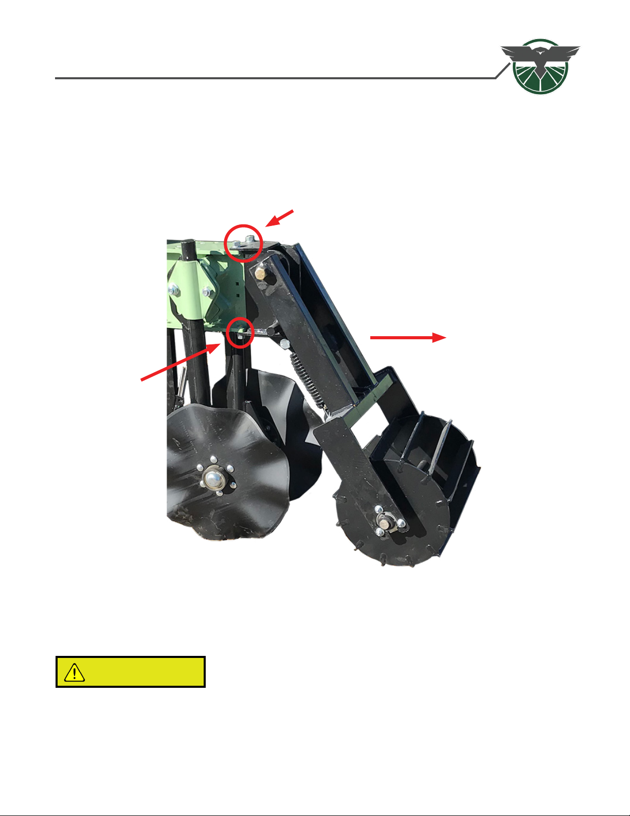
(1) Remove Orthman™ 1tRIPr™ Basket
1.1 - Using 3/4”Wrench and Rubber Mallet, carefully remove Orthman™ 1tRIPr™ Basket. All
parts can be set aside and will NOT be reused.
CAUTION
To avoid crushing hazard, DO NOT place any body part beneath the basket as you remove it.
Remove
Remove
Remove

INstallation Guide
(2) Bolt in Basket Adapter (321590)
2.1 - Using four (4) Carriage Bolts (411785), four (4) 1/2” Lock Washers (413508) and four (4) 1/2”
Nuts (412058), attach the Basket Adapter (321590) to the 1tRIPr™ row unit.
NOTE: Due to OEM Frame Variations, some bolt heads may be tight to frame.

INstallation Guide
(3) - Pin new Optimizer Basket into Adapter
3.1 - Pin new Basket Insert (321592) into Basket Adapter (321590) using Pin (333099) and
securing with Pin Clip (333021).
CAUTION
To avoid crushing hazard, DO NOT place any body part beneath the Optimizer Basket while pinning
basket into adapter.
(3.1)
Note: Rib goes toward
rear of machine.

INstallation Guide
(4) - Pneumatic System Installation
• The Optimizer Basket System has an air requirement of 120 psi of clean, dry air. A 12-volt, 50% duty
cycle air compressor with one gallon tank is recommended.
• The system uses 1/4”OD Push-to-Connect Air Line.
• The line should be secured with zip ties. Do not crush air line by overtightening zip ties.
• Test air line tment on one row before routing all rows.
• Rows are designed to be tied into the main line and secured to the toolbar.
• Make sure air line is secured and free of any pinch or wear points through the entire movement of the
row unit and toolbar.
• To ensure sealing, tube ends need to be cut smooth and square.
• Ensure regulator exhaust line is routed out away from regulator and down to prevent moisture from
entering into the system.
NOTE: See next page for Air Hose Diagram.
INstallation Guide
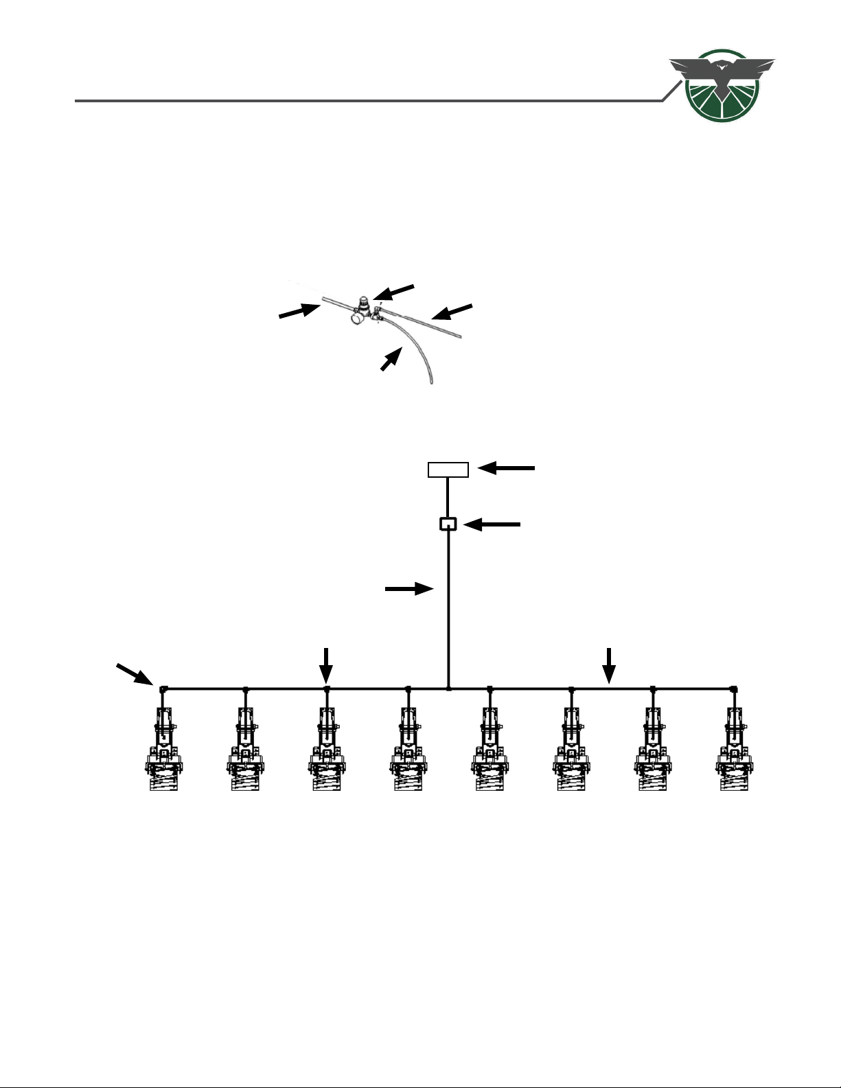
Air Hose Diagram
• Each row will connect to the main line with a 1/4” TEE Fitting and end rows connect to the main
line with a 1/4” PTC 90˚ Fitting.
• The location of the supply line to the main line is unimportant.
• The air ows from the air compressor, to the air regulator, to the supply line, to the row unit line, and
nally to the air bag.
Supply Line
From
Air Compressor
Exhaust Line
Air Regulator
Air Regulator
Regulated Air
¼” OD Air Line
¼” OD Union TEE Fitting
¼” OD 90˚ Fitting
Air Compressor

INstallation Guide
4.1 - Route 1/4” air line to air bag in Optimizer Basket. Retain hose in integrated zip tie mount.
4.2 - Plumb all lines in parallel as shown on page 13, from an air regulator to the Optimizer Baskets.
NOTE: Length will vary by model of 1tRIPr™. We recommend a 5’ air line for 2009 and newer
machines, older will be 6’or longer.
(4) - Pneumatic System Installation (continued)
Airbag
Fitting Integrated
Zip-tie Mount
Table of contents
Popular Spreader manuals by other brands

Equalizer International
Equalizer International SG13TE Operator's instruction manual

LEHNER
LEHNER SuperVario X Operating instructions with spare parts list

Western
Western 110 owner's manual

Fisher
Fisher STEEL-CASTER installation instructions

Western
Western PRO-FLO 2 owner's manual

Amazone
Amazone ZA-M 1002 Special Easy operating manual


Millcreek
Millcreek 100P Operator's manual

IRIS Spreaders
IRIS Spreaders IPS-200 Operator's manual

Curtis
Curtis Fast-Cast 175 Installation & owner's manual

SnowEx
SnowEx Vee Pro 3000 manual

Swenson Spreader
Swenson Spreader S Series Installation and operating instruction manual

Buyers
Buyers SaltDogg SHPE3000 installation instructions