Haws VRKHO1 Guide

07/20 Model VRKHO1 Page 1 of 4
NO. OOO2076521 (0)
1455 Kleppe Lane Sparks, NV 89431-6467 (775) 359-4712 Fax (775) 359-7424
No. 0002080407 (2)
Model VRKHO1
24 VAC SENSOR
INSTALLATION, OPERATION
&
MAINTENANCE INSTRUCTIONS
LIMITED WARRANTY
HAWS®warrants that all of its products are guaranteed against defective material or poor
workmanship for a period of one year from date of shipment. HAWS liability under this
warranty shall be discharged by furnishing without charge F.O.B. HAWS Factory any
goods, or part thereof, which shall appear to the Company upon inspection to be of
defective material or not of first class workmanship, provided that claim is made in writing
to company within a reasonable period after receipt of the product. Where claims for
defects are made, the defective part or parts shall be delivered to the Company, prepaid,
for inspection. HAWS will not be liable for the cost of repairs, alterations or replacements,
or for any expense connected therewith made by the owner or his agents, except upon
written authority from HAWS, Sparks, Nevada. HAWS will not be liable for any damages
caused by defective materials or poor workmanship, except for replacements, as provided
above. Buyer agrees that Haws has made no other warranties either expressed or implied
in addition to those above stated, except that of title with respect to any of the products or
equipment sold hereunder and that HAWS shall not be liable for general, special, or
consequential damages claimed to arise under the contract of sale.
The emergency equipment manufactured by HAWS is warranted to function if installation
and maintenance instructions provided are adhered to. The units also must be used for
the purpose, which they were intended. This product is intended to supplement first-aid
treatment. Due to widely varying conditions HAWS cannot guarantee that the use of this
emergency equipment will prevent serious injury or the aggravation of existing or prior
injuries.
NO OTHER WARRANTIES EXPRESSED OR IMPLIED ARE AUTHORIZED,
PROVIDED OR GIVEN BY HAWS.
NOTE TO INSTALLER: Please leave this information with the Maintenance Department.
SHOULD YOU EXPERIENCE DIFFICULTY WITH THE INSTALLATION OF THIS
MODEL, PLEASE CALL: 1-800-766-5612
FOR PARTS CALL: 1-800-758-9378
(U.S.A. AND CANADA ONLY) MONDAY-THURSDAY: 6:00 A.M. –4:00 P.M. PST
FRIDAY: 6:00 A.M –1:00 P.M. PST

07/20 Model VRKHO1 Page 2 of 4
Recommended Tools: 5/64” Hex Key wrench, 11/32” socket wrench or open-end wrench.
INSTALLATION PROCEDURE
Step 1: Remove grille, shut off water supply and disconnect power from 24VAC transformer.
Step 2: Remove bottom plate from fountain using 5/64” Hex key wrench.
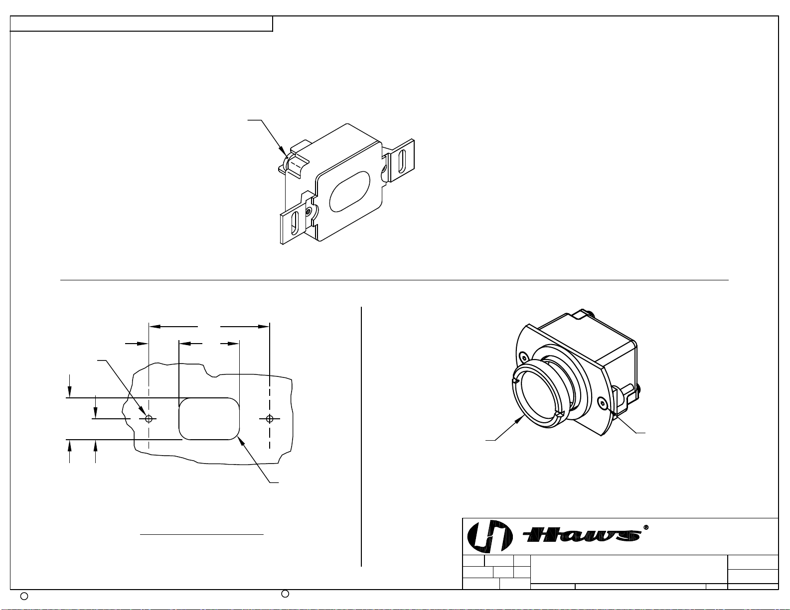
Step 3: Remove sensor to be replaced using 11/32” socket wrench and disconnect leads to sensor.
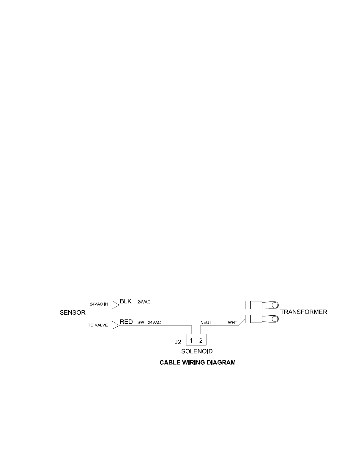
*With older style 24VAC H.O. sensor, unplug sensor from cable assembly. Snip off the 3
position connect from cable assembly and tape off or, with a wire nut, insulate the white wire
(this wire, neutral, is not required with new style sensor.)
Step 4: Connect leads from cable assembly to sensor. Black lead to “24VAC IN” and red lead to “TO
VALVE”.
Step 5: Install sensor.
Step 6: Reconnect power to the 24VAC transformer. This will initiate the sensor’s “start-up mode”.
“Start-up mode”for the H.O. sensor will take approximately five (5) minutes to complete its
full cycle of self-calibration. It is important that no object is in front of sensor during this time.
A steady red light visible in the center of the sensor window indicates the sensor is in “start-
up mode”. If the red light is flashing, this indicates that the sensor is picking up an object.
Unless this object is a permanent fixture, (i.e. a wall, a plant, etc.), it must be removed from
the view of the sensor. The sensor will adapt itself around such permanent fixtures. In this
mode, the sensor will take up to ten (10) minutes to calibrate.
NOTE:
1. If the 24VAC power supply is interrupted for more than fifteen (15) seconds, the “start-up
mode” will automatically repeat itself when power is restored.
2. If the indicator light flashes three (3) times quickly, then three (3) times slowly and
continues to repeat this sequence, this indicates incorrect wiring or a short in the 24VAC
power supply.
3. When someone remains standing in front of the sensor for more than thirty (30) seconds,
the sensor will automatically shut off the water supply to the bubbler. To restart, stand to
the side for a moment, then return to a position in front of the sensor.
Step 7: Turn water supply on and adjust the bubbler’s flow using the black regulator mounted next to
the solenoid valve. Finally, check fountain for leaks. Verify the chiller turns off after water
reaches proper temperature. If there are any problems, refer to sensor’s Troubleshooting
Guide.
Step 8: Re-install bottom plate and grille.

07/20 Model VRKHO1 Page 3 of 4
SENSOR TROUBLESHOOTING GUIDE
Step 1: A loud click indicates when the solenoid valve is turned on. If valve clicks, but no water
comes on make sure screwdriver stop is wide open (turn counterclockwise). If valve clicks
but still no water, check valve or line for obstruction. If valve does not click when hand is
placed a few inches in front of sensor, go on to next step. DO NOT ATTEMPT TO
DISASSEMBLE SENSOR, DAMAGE WILL RESULT.
Step 2: Using volt meter, check for 24VAC across the transformer terminals. Replace transformer if
faulty.
Step 3: Check solenoid valve. Voltage rating on valve top plate should be 24VAC. Unplug sensor
from wiring harness. Using a volt meter, check for 24VAC signal from wiring harness (use
hand in front of sensor to activate).
Valve coil may be checked for continuity using an Ohm meter. Disconnect valve from wiring
harness and sensor wires. Connect each valve lead to a meter lead. One meter lead should
be plugged into meter ground socket and one should be plugged into socket marked “Ohm”.
Coil resistance should be around 10 –20 Ohms. If resistance is near infinity or zero, solenoid
coil is at fault. Coils may be easily replaced without disconnecting valve body from plumbing.
Replace with new 24VAC rated coil.
Step 4: Check wiring harness. If wiring harness appears to be hooked up correctly, disconnect
harness from valve, sensor and power cord, then check harness for continuity using Ohm
meter. Resistance between connectors attached to each other by wires should be near zero
Ohms. High resistance indicates a faulty connector or wire. There should be infinite
resistance between separate (independent) legs of the wiring harness. Less than infinite
resistance indicates a short or cross connection. If wiring harness has proper continuity and
is hooked up properly, proceed to Step 5.
Step 5: Check sensor. If Steps 2, 3 and 4 all check out OK, the sensor is probably the problem. The
sensor acts pretty much like a simple relay or switch. The SCR (semiconductor relay) within
the sensor will not fully switch without a 6 to 11 Watt load such as a solenoid valve or
household light bulb. For this reason, a simple Ohm meter test on a good sensor which is not
connected to the proper load will yield misleading results seemingly indicating improper
function.
© 2020 Haws®Corporation –All Rights Reserved
HAWS® and other trademarks usedin these materials are the exclusive property of Haws Corporation.

* MUST BE USED IN CONJUNCTION WITH
24VAC TRANSFORMER AND SOLENOID
PANEL CUT-OUT
REF "24VAC IN"
.813 1.625
3.250
.563
1.125
Ø .177 2X
R .312 4X
APPROVED:
DRAWN:
PART NUMBER
SCALE: SHEET OF
REVISION
DRAWING TYPE: SIZE: A
BY:ECN NO.
PAGE
DATE:
DATE:
ECN:
REVISED PER
CHK'D.:
PAGE
Haws Corporation - All Rights Reserved. HAWS and other trademarks used in these materials are the exclusive property of Haws Corporation.
CR
MODEL(S)
1455 KLEPPE LANE
SPARKS, NEVADA 89431
(775) 359-4712 FAX (775) 359-7424
E-MAIL: [email protected]
WEBSITE: WWW.HAWSCO.COM
THIS DOCUMENT IS TRUE AND CORRECT AT TIME OF PUBLICATION. CONTINUED PRODUCT IMPROVEMENTS
MAKE SPECIFICATIONS AND MEASUREMENTS SUBJECT TO CHANGE WITHOUT NOTICE.
G. EXLINE
05/10/94
2
0002080407.D
VRKHO1
N/A
11
FV
08/14/20
1370
SLS
4 of 4
INSTALLATION
5568
4 of 4
2020
FV
OLD VERSION
CURRENT VERSION
REMOVE
BEZEL NUT TO
ALLOW ACCESS
SCREWS ON
EITHER SIDE
SECURE SENSOR
HO SENSOR CAN BE MOUNTED IN
EITHER APPLICATION SHOWN BELOW
(PANEL NOT SHOWN)
Table of contents
Other Haws Accessories manuals