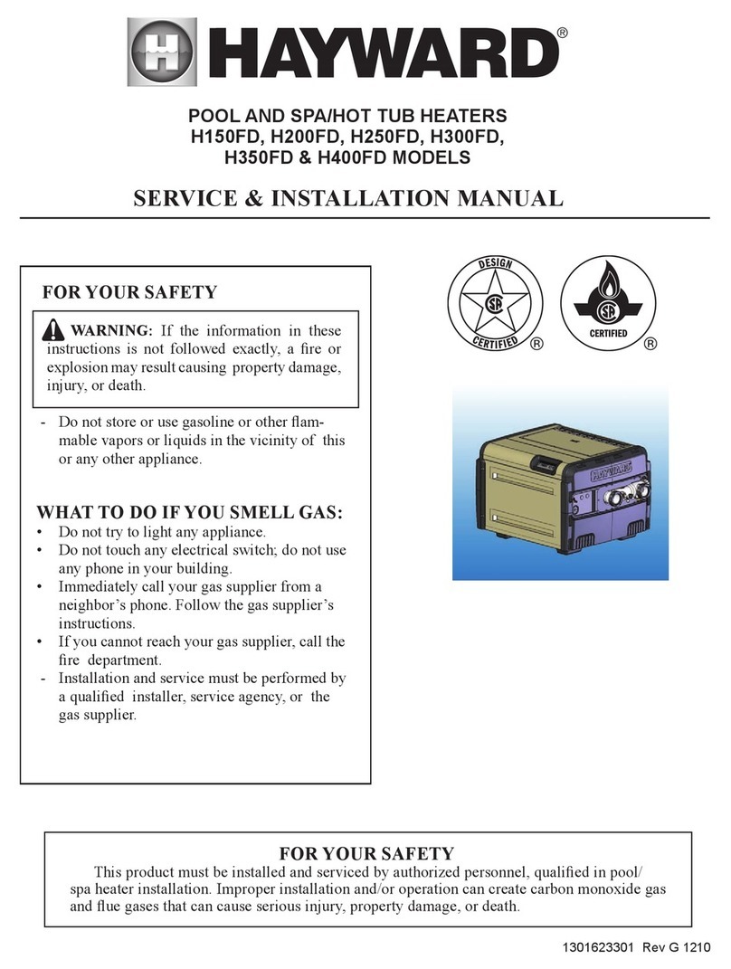
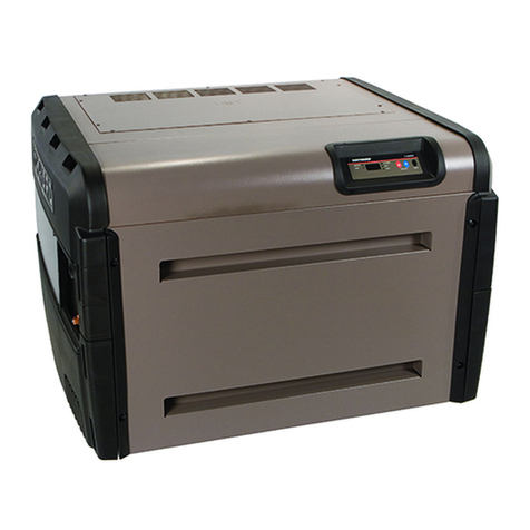
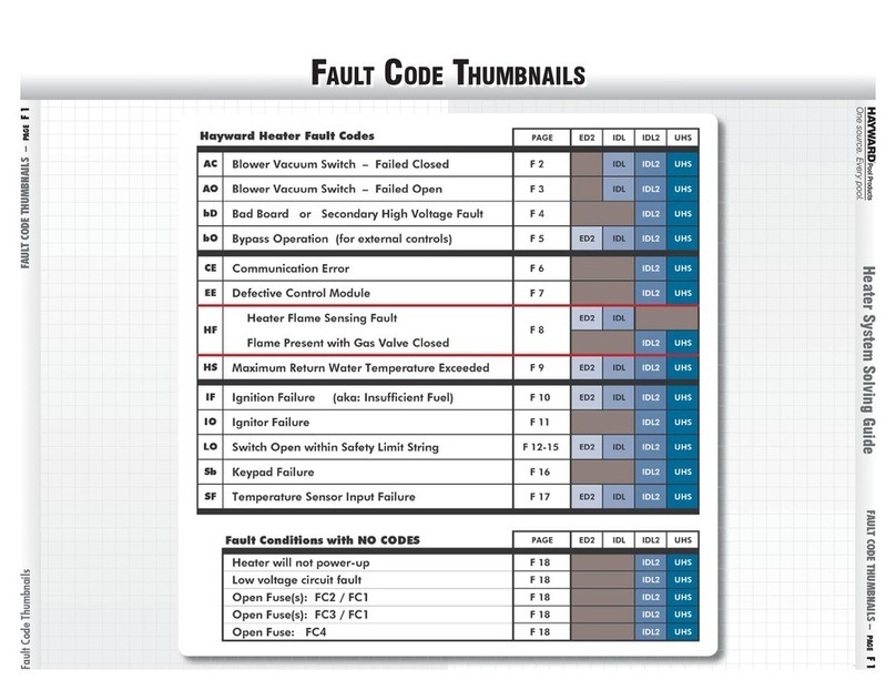
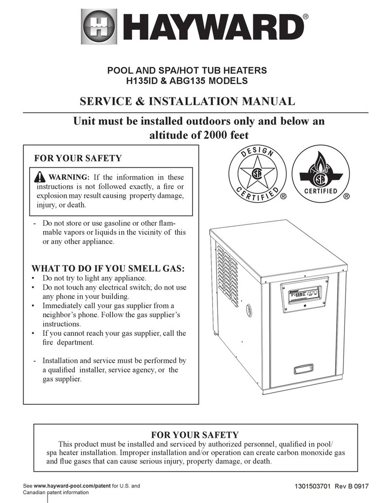
Hayward HC Series User manual

Universal HC Series Heater ®
Troubleshooting Guide
TSG-UHC21a Copyright 2021 Hayward Holdings

High Voltage Electrocution Hazard
Hazardous voltage can shock, burn, cause serious injury
and or death. To reduce the risk of electrocution and or
electric shock hazards:
•Turn off power to unit before making repairs
•Only qualified technicians should service heater
•Replace damaged wiring immediately
•Ensure appliance is properly grounded and bonded
2
!
Warning
Safety Precautions

ICB and Fuse Board Layout
4-
5
Troubleshooting: (cont.)
Pg.
27
-57
Sequence of Operation: Normal/Failure to Light
6
5. “BD” Code
38
Gas and Electrical Connections
7
6. "EE" or "CE" Code
39
How To:
Pg.
8-
26
7. "IO" or "SB" Code
40
Program Heater Bypass & Temperature Lockout
9-
11
8. "SF" or "HS" Code
41
Change/Replace Gas Mixer
12
9. "PF" Code
42
Test/Adjust Gas Pressure
13
-15
10. “HF” Code
43
Burner Inspection
16
-19
11. "LO: Code
44
-47
Change/Replace Combustion Chamber
20
-26
12. "IF" Code
48
-49
Troubleshooting:
Pg.
27
-57
13. "AC" Code
50
Diagnostic Codes and Part Numbers
28
-29
14. "A1, A2, A3" Codes
51
-53
Wiring Diagram
30
15. "b1" Code
54
1. Heater not powering up
31
-33
16. "b2" Code
55
2. Open FC1&/FC2 Fuse
34
17. "b3" Code
56
3. Open FC3&/F1 Fuse
35
-36
18. "b4" Code
57
4. Open FC4 Fuse
37
3
Table of Contents

4
A
Remote Control: 24VAC (E1)
B
Flame Sensor (E4)
C
Temperature Sensor (E2)
D
Display Output: 24VAC (E7)
E
3A Fuse (F1)
F
Low Voltage R & C: 24VAC (E12,
E13)
G
Gas Valve & Safety Switches:
24VAC (E11)
H
High Voltage: 120VAC (E10)
I
Blower/Inducer (E6)
JIgnitor (E3)
C
H
G
F
D
E
JI
B
A
Integrated Control Board Layout (ICB)

5
Field Wiring Panel Layout
G
A
C
F
B
D
E
ATransformer Secondary: 24VAC
(right) &
120VAC (left) (P4)
BVoltage Selector 240 OR 120VAC
determined by plug (P2): NOTE: 240
VAC
plug factory installed
CFuse: 3a protects transformer high
voltage secondary, will fail with blower,
ignitor or ICB failure (FC4)
D
Fuse: 3A protect primary input voltage,
will fail with excessive voltage, improper
wiring, shorted transformer or fuse
board (FC1 & FC2)
EHigh Voltage Output: 120VAC (P6)
FLow Voltage Output: 24VAC (P5)
G
Transformer Primary: 120/240VAC (P3)
H
Power connection for junction boxes:
120/240VAC (P1)
H

The control continually compares the set temp to the actual water temp.
When the water temp is 1º below the set point the following sequence starts:
6
UHC Sequence of Operation: Normal

7
UHC Electrical & Gas Connection
Bonding Lug
Low Voltage
Gas Port
Alternate
Gas Port
Low Voltage
Wiring
High/Line
Voltage
L1
LN
L2 G
G
240V
Factory Wired
120V
See Manual
The low voltage and high/line voltage compartments can be reversed but NOT shared.

Universal HC Series Heaters®
How To:

9
How To: Program Heater Bypass Operation
Follow the included steps to place the heater in bypass operation for external control.
NOTE: the maximum temperature set point is 104° F.
Press the ‘MENU ICON’ button to place the
heater in ‘STANDBY’. Press and hold the ‘MINUS’ button and ‘MENU
ICON’ button for 3 seconds.
‘bo’ will appear on the display when the
heater has successfully entered bypass
operation.
Once in bypass, press the ‘MENU ICON ’
button until ‘POOL’ or ‘SPA’ is illuminated.
Step 2
Step 3 Step 4
Step 1

10
How To: Program Temperature Lock-Out
NOTE: The default Max temp set points are 90ºF (Pool) 104ºF (Spa).
When setting the max temp lock-out set point, the LEDs & display should flash rapidly.
Press the ‘MENU ICON’ button to place the
heater in ‘STANDBY’ mode. Press and hold the minus & plus buttons for 3
seconds.
The ‘SPA’ indicator will flash & the display
should show the Max Temp set point. Raise or lower the temperature displayed
using the minus or plus button.
Step 2Step 1
Step 3 Step 4
Follow the included steps to lock the maximum temperature allowed.

11
How To: Program Temperature Lock-Out (cont.)
Press the ‘MENU ICON’ button to toggle to the
‘POOL’ now that the ‘SPA’ is set. Raise or lower the temperature displayed
using the minus or plus button.
To finalize, press the ‘MENU ICON’ button
until the heater goes back into ‘STANDBY’.
Step 6Step 5
Step 7
NOTE: The default Max temp set points are 90ºF (Pool) 104ºF (Spa).
When setting the max temp lock-out set point, the LEDs & display should flash rapidly.

Turn power off, remove the 4 screws from the
header controls cover and remove the panel.
Remove screws from control cover
Lift the cabinet top slightly, then remove the 4
screws from the control cover and remove.
Remove screws from header cover
Step 1 Step 2
Remove pressure hose from front of fuel/air mixer.
Rotate mixer clockwise and pull straight out to
remove.
Remove fuel/air mixer
12
Re-install/install new mixer back into blower and
rotate counter clockwise to reinstall and reconnect
pressure hose to front of fuel mixer.
Re-install/install fuel/air mixer
Step 3 Step 4
How To: Change/Replace Fuel/Air Mixer

Turn off gas supply to heater. Gas readings should
be in line with the chart above.
Inlet: Remove test plug from inlet
Locate the inlet test port on the side of the gas
valve, and remove the 1/8” Allen plug.
Turn off gas supply
Install a 1/8” barbed fitting and connect the
positive (+) hose from the manometer to the
barbed fitting. Turn the gas on to the heater.
Connect Manometer
13
Leave the heater in “Stand By”, your static pressure
should be no less than +4.0 and no greater than
+14.0” WC.
Test Inlet Pressure
How To: Test/Adjust Gas Pressure
Step 1 Step 2
Step 3 Step 4
+10.0
InH2o

Turn off gas supply to heater. Remove 1/8” Allen
plug from the pressure port on the gas valve.
Locate test ports
Install barbed fitting from manometer in the
pressure port of the gas valve..
Turn off gas supply
Remove the silicone tubing from the vent port on
the gas valve, leaving the barbed fitting installed
on the gas valve.
Remove test port plug(s)
14
Connect the negative side of your manometer to
the pressure port. Connect the positive side to the
vent port as show above. You will need a 3/16”
barbed “T” for your manometer.
Connect manometer
How To: Test/Adjust Gas Pressure
Step 1
Step 3
Step 2
Step 4
+ -
+
-

NOTE: IF incoming gas pressure is within range, then your manifold pressure should be correct per factory settings.
Once the manometer is connected, turn gas back on
& test inlet & manifold gas pressures. Go to Step 6.
Verify Pressures are correct
IF inlet pressures are correct AND the manifold
pressure is high or low, go to step 7.
Manometer Connected
Remove plug from gas valve with a flat head
screwdriver. Go to Step 8
Remove plug from gas valve
15
Once removed, increase pressure by rotating screw
clockwise, (counter clockwise to reduce pressure).
Adjust gas pressure
How To: Test/Adjust Gas Pressure (cont.)
Step 8
Step 6
Step 7
Step 5

Remove cabinet top
Carefully lift up on the top of the heater cover and
disconnect the ribbon cable from the display, then
remove cabinet top.
Remove screws from both sides
Remove the one screw that holds the right side
electrical cover and remove cover.
Remove electrical cover
Step 3
16
Locate and remove the 4 screws from the right side
sheet metal and lift up to remove the sheet metal.
Remove right side sheet metal
Clean/Replace Burner
Turn the Power and the gas off to the unit. Remove
the 2 top screws on each side of the heater as
shown above.
Step 4
Step 1 Step 2

17
Step 5 Step 6
Disconnect the Blower/Inducer (E6) wire harness
from the ICB Board.
Disconnect wiring
Loosen the flare nut from the gas manifold closest
to the blower. Gently pull the manifold out of
blower.
Remove the silicone tubing from both ports on the
blower. Make note of where each tube ends for re-
installation.
Remove silicone tubing
Loosen flare nut
Remove the 16 screws from the burner to release
the entire blower and burner assembly.
Remove burner screws
Step 7 Step 8
Clean/Replace Burner (cont.)

18
Lift straight up to remove blower assembly from
the burner. Gently lay the blower aside.
Remove blower assembly
Step 11
Remove blower/burner assembly
Slide left slightly and then lift the blower / burner
assembly straight up out of the heater.
Remove the 4 each 7/16” nuts that hold the blower
assembly to the burner.
Remove blower nuts
This is showing you a clean burner rear and front
view.
Clean burner
Step 9
Step 12
Step 10
Clean/Replace Burner (cont.)

Blow out burner
Using compressed air blow the burner out from the
front to the rear. Make sure that you blow around
all four corners.
19
Turn the burner over and shake out any loose dirt
and debris. You can use a wet dry vac to vacuum
any smaller particles out of the burner.
Vacuum burner
Step 14
Clean/Replace Burner (cont.)
Step 13

Remove screw from Display
Using a 5/16 nut driver or #2 Phillips Head
screwdriver, remove screw from below display.
Disconnect gas & water unions
Step 1 Step 2
Lift cover and locate the quick disconnect for the
ribbon cable. Press down on tab and pull apart.
Disconnect ribbon cable
Step 3
20
Locate and remove the 2 screws from the top of
each side of the heater (shown above).
Remove top cover screws
Step 4
Change/Replace Combustion Chamber
Turn Power and gas off to unit, disconnect the gas
line and plumbing unions from the heater.
Gas pipe
This manual suits for next models
2
Table of contents
Other Hayward Heater manuals

Hayward
Hayward Universal H-Series Low NOx User manual
Hayward
Hayward ED2 Administrator guide

Hayward
Hayward Universal H-Series Low NOx User manual

Hayward
Hayward H150FDN User manual

Hayward
Hayward H135ID User manual

Hayward
Hayward H250FDN User manual

Hayward
Hayward H150FDAU User manual

Hayward
Hayward C-SPA-XI 5.5 User manual
Popular Heater manuals by other brands

Chromalox
Chromalox UB-1002E Installation, operation and renewal parts identification

Sovelor
Sovelor MT30 Use and maintenance book

Zibro
Zibro SRE 169 operating manual

Aleko
Aleko NTSA Series Installation and operating instructions

Panasonic
Panasonic FV-11VH2 installation instructions

Electric House
Electric House 69520 instruction manual