Hayward HRSN4FS Series Manual

USE ONLY HAYWARD GENUINE REPLACEMENT PARTS
HRSN4FSIOM Rev E ECR 132V
Page 1 of 32
Hayward Flow Control
1-888-HAY-INDL (1-888-429-4635) www.haywardowcontrol.com
TO PREVENT POTENTIAL INJURY OR DAMAGE TO PROPERTY, READ THIS MANUAL CAREFULLY AND COMPLETELY.
INSTALLATION, OPERATION AND
MAINTENANCE INSTRUCTIONS
HRSN4FS Series with Battery Backup
Back to TOC

USE ONLY HAYWARD GENUINE REPLACEMENT PARTS
HRSN4FSIOM Rev E ECR 132V
Page 2 of 32
Hayward Flow Control
1-888-HAY-INDL (1-888-429-4635) www.haywardowcontrol.com
WARNING - Read and follow all instructions in this IOM manual and on the equipment. Failure
to follow instructions can cause severe injury and/or death.
WARNING – Risk of Electric Shock. All electrical wiring MUST be in conformance with
applicable local codes, regulations, and the National Electric Code (NEC). Hazardous voltage can
shock, burn, and cause death or serious property damage. To reduce the risk of electric shock, do
NOT use an extension cord to connect unit to electric supply. Provide a properly located electrical
receptacle. Before working on any electrical equipment, turn off power supply to the equipment.
WARNING – To reduce the risk of electric shock replace damaged wiring immediately.
WARNING – Ground all electrical equipment before connecting to electrical power supply.
Failure to ground all electrical equipment can cause serious or fatal electrical shock hazard.
WARNING – Do NOT ground to a gas supply line.
WARNING – To avoid dangerous or fatal electrical shock, turn OFF power to all electrical
equipment before working on electrical connections.
WARNING – Failure to bond all electrical equipment to system structure will increase risk for
electrocution and could result in injury or death. To reduce the risk of electric shock, see installation
instructions and consult a professional electrician on how to bond all electrical equipment. Also,
contact a licensed electrician for information on local electrical codes for bonding requirements.
CAUTION – Potential pinch point. Equipment connected to or driven by this device may start
unexpectedly and may cause personal injury or entrapment in linkage systems.
Basic safety precautions should always be followed, including the following: Failure to follow instructions
can cause severe injury and/or death.
This is the safety-alert symbol. When you see this symbol on your equipment or in this manual, look
for one of the following signal words and be alert to the potential for personal injury.
WARNING warns about hazards that could cause serious personal injury, death or major property
damage and if ignored presents a potential hazard.
CAUTION warns about hazards that will or can cause minor or moderate personal injury and/or
property damage and if ignored presents a potential hazard. It can also make consumers aware of
actions that are unpredictable and unsafe.
A notice indicates special instructions that are important but not related to hazards.
Notice:
IMPORTANT SAFETY INSTRUCTIONS
Back to TOC

USE ONLY HAYWARD GENUINE REPLACEMENT PARTS
HRSN4FSIOM Rev E ECR 132V
Page 3 of 32
Hayward Flow Control
1-888-HAY-INDL (1-888-429-4635) www.haywardowcontrol.com
Important Safety Instructions ......................2
Table of Contents ................................3
Actuator Operational Concepts ..................3
Technical Information ............................4
Conventions Used in this Manual ................4
Actuator Handling and Installation ..................5
Shipping and Handling ........................5
Installation Notes .............................5
Product Mounting and Setup ......................6
Torque Switches ................................7
Component Identication .........................8
120/230V Transformer Mounting and Setup ...........9
Power Supplies ..............................9
Adjusting CW End of Travel ......................10
Adjusting CCW End of Travel .....................11
Adjusting Auxiliary Switches ......................12
Cam Behavior ...............................12
Auxiliary Switch Cam Mapping ..................12
Commissioning ................................13
On/Off Control ..............................13
Battery System Connection ......................14
On/Off Control ..............................14
Calibration ....................................16
On/Off Control ..............................16
Commissioning ................................18
Proportional Control .........................18
Battery System Connection ......................19
Proportional Control .........................19
Calibration ....................................20
Proportional Control .........................20
Troubleshooting ................................22
On/Off Models ..............................22
Proportional Models .........................23
Battery System .............................24
Mechanical Data ...............................25
Dimensional Data ...........................25
Exploded View ..............................26
Wire Sizing Chart ...............................27
Wiring Diagrams ...............................28
HRSN4A~4D..20 ............................28
24VAC/VDC On/Off Control .................28
HRSN4A~4D..20 ............................29
24VAC/VDC Proportional Control ............29
HRSN4A~4D..20 ............................30
120/230VAC All Control Types ...............30
Notice: The actuator is shipped with the battery system disconnected until the unit is commissioned after all
installation procedures have been completed (see pg 14 or 19).
Notice: Read the project specications and understand the application before making an actuator selection. If
in doubt, consult with the project engineer to clarify what is actually required for a fully operational installation.
We have provided in this document all the tools necessary to determine how the various levels interface to the
outside world. If there are any questions, please contact Hayward Flow Control Technical Services.
The HRSN4 Series actuators ending in “20” or in “2X” have an internal battery backup system and are quarter-
turn industrial electric actuators designed to operate valves and dampers in municipal, heavy commercial
or industrial applications. These units are NEMA 4/4X, IP67 rated, and feature on/off or proportional control
versions to interface to most eld control signals. The HRSN4 Series with battery backup operate on 24vac or
24vdc power supplies. Hayward offers 120v and 230v transformers packaged in stainless steel wall mounted
enclosures sized to provide the required power for the actuator and the battery system.
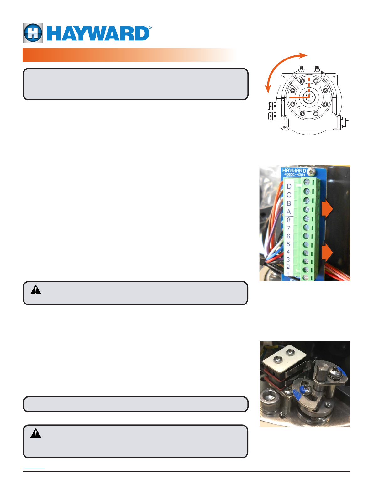
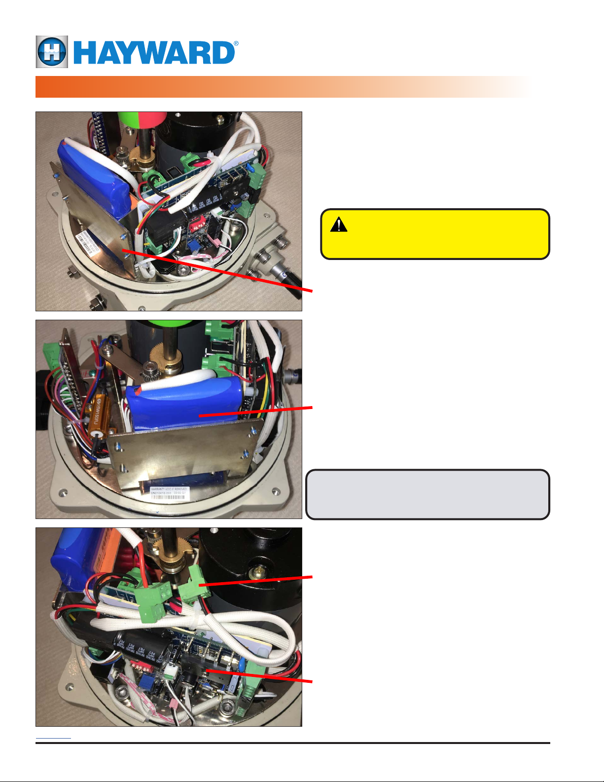
The battery pack and charge controller are housed in a side-mounted enclosure that is integral to the actuator
lower housing. Wiring of the actuator and battery system is completed through access to a single terminal
location. The battery system is designed to provide a minimum of two years of eld service (depending on
application and actual conditions of use). The battery pack is eld replaceable.
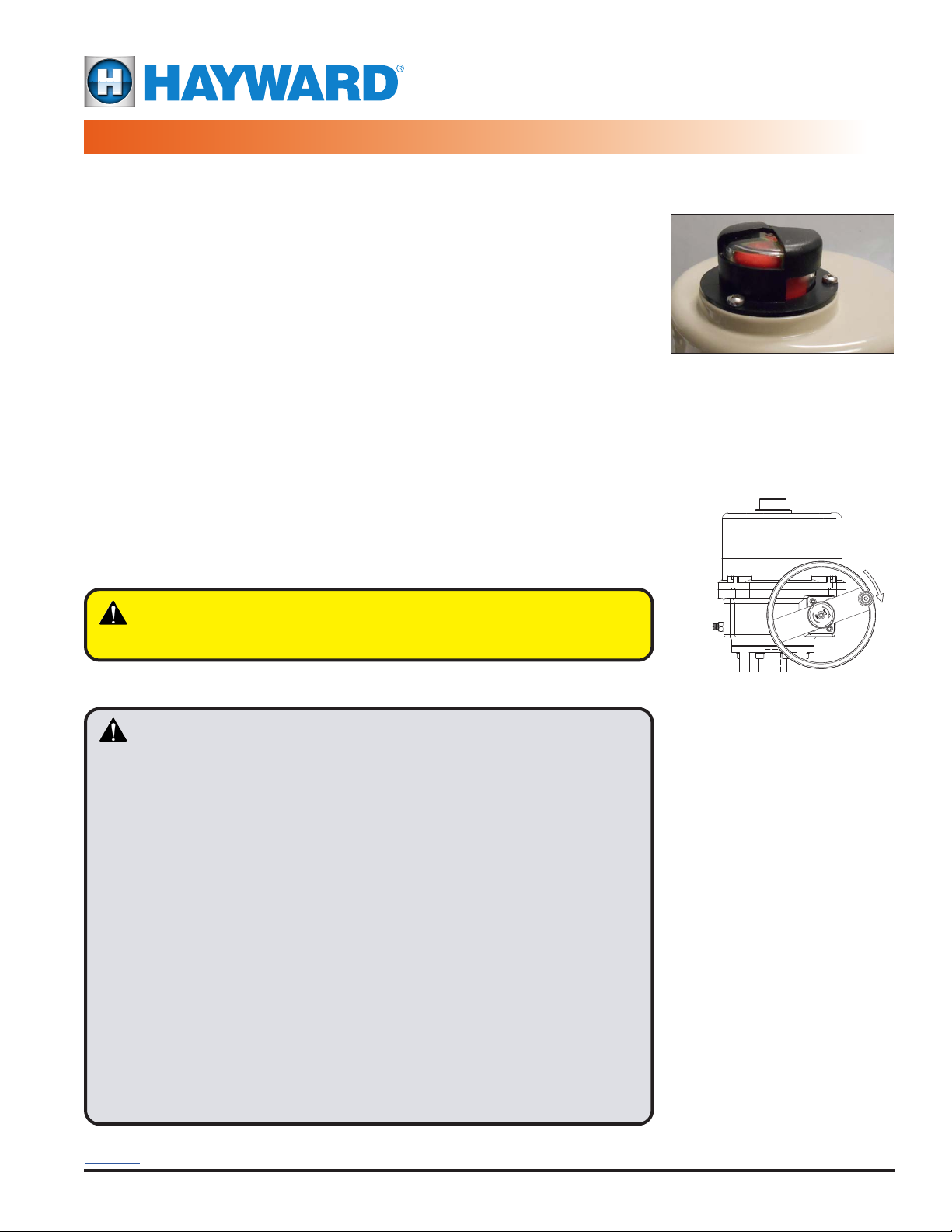
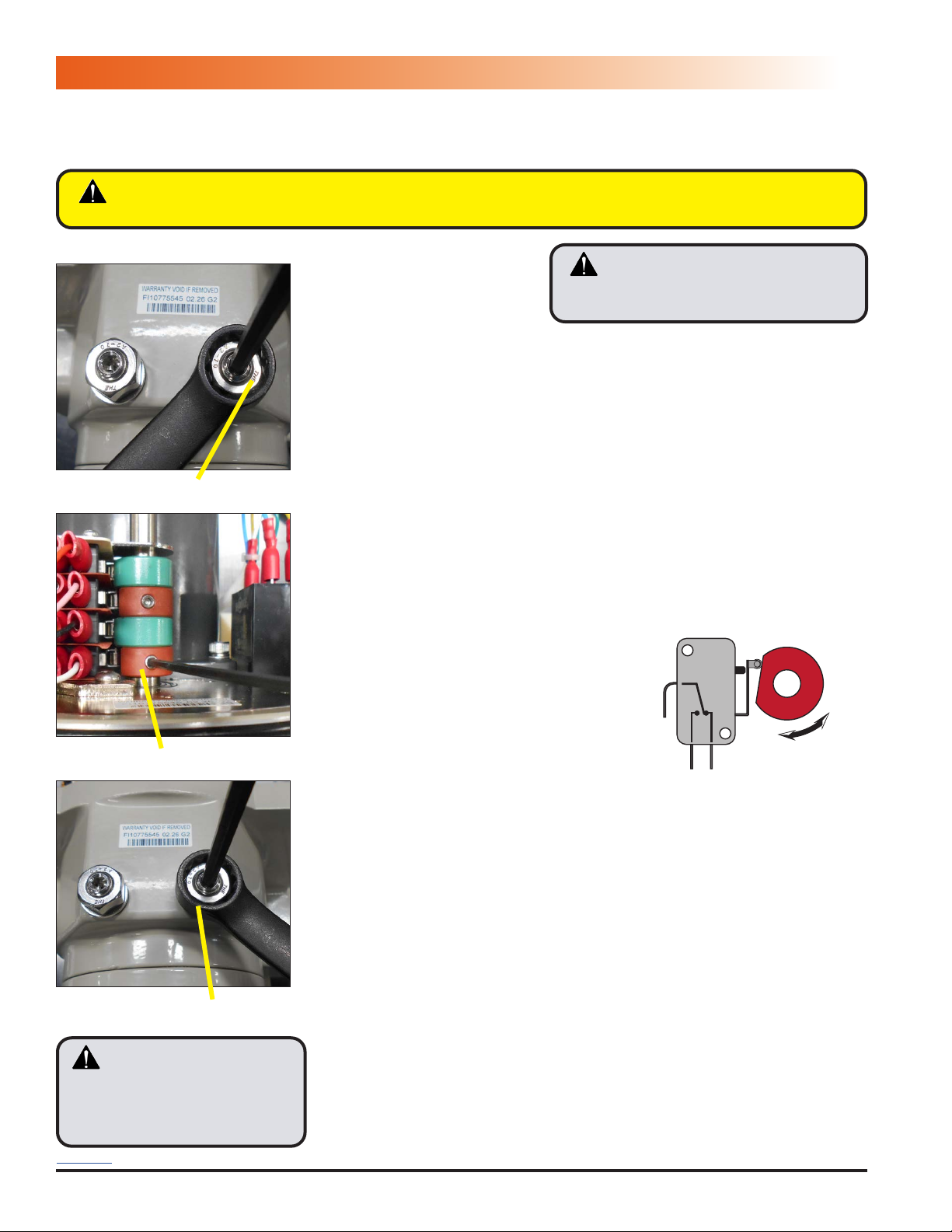
Notice: HRSN4 Series actuators are fully assembled, calibrated and tested prior to leaving our factory. In most cases, after
you have mounted the actuator to your device, you should be able to operate the actuator from fully CLOSED (CW) to fully
OPEN (CCW) and back again, and nd that no adjustments are needed. The assembly can be put into service immediately.
However, should it be necessary to make adjustments to the end-of-travel positions to overcome any device related issues
(i.e. valve shaft incorrectly timed to the drive stem), the procedures outlined below should be followed to put the assembly
into service. Note that there is a maximum adjustment range of +/- 3° at each end of travel.
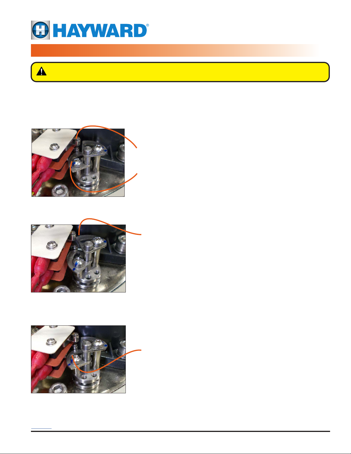
Pages 10-11 - Travel limits for CW (CLOSED) & CCW (OPEN) positions, HRSN4 Series
Page 12 - Auxiliary switch cams for CW & CCW positions, HRSN4 Series
TABLE OF CONTENTS
HRSN4FS Series
Battery Backup
ACTUATOR OPERATIONAL CONCEPTS
Back to TOC

USE ONLY HAYWARD GENUINE REPLACEMENT PARTS
HRSN4FSIOM Rev E ECR 132V
Page 4 of 32
Hayward Flow Control
1-888-HAY-INDL (1-888-429-4635) www.haywardowcontrol.com
Control Voltage Torque Switches Fail Safe Local Control Station IOM Wiring Diagram Page
On/Off 24VDC/VAC XTS/TS FS None This IOM 28
Proportional 24VDC/VAC XTS/TS FS None This IOM 29
On/Off 120VAC * XTS/TS FS None This IOM 30
Proportional 120VAC * XTS/TS FS None This IOM 30
On/Off 230VAC * XTS/TS FS None This IOM 30
Proportional 230VAC * XTS/TS FS None This IOM 30
* Requires use of a transformer to convert supply voltage to 24V.
ACTUATOR OPTIONS
Below are Terms and Denitions used throughout this manual.
1. XTS/TS product manufactured without/with Torque Switches.
2. FS product manufactured with Fail Safe built-in.
3. LCS is an industry acronym for a Local Control Station.
4. CW is Clockwise and CCW is Counterclockwise.
CONVENTIONS USED IN THIS MANUAL
Use this table to efciently select the actuator and wiring diagram you require.
ACTUATOR SPECIFICATIONS
(20 SERIES)
Supply Torque Output (lbf-in / Nm) 3540 / 400 5310 / 600 7080 / 800 8850 / 1000
24VAC
-
24VDC
Current Draw (Start / Run / LRA) 7.0A / 5.8A / 15A 7.0A / 5.8A / 15A 7.0A / 5.8A / 15A 10.5A / 7.8A / 22A
Speed (90°) DC-60Hz/50Hz, seconds 21 / 21
28 / 28 34 / 34 34 / 34
Motor - 24V DC Perm Magnet 2 Pole Brush
40W 40W 40W 90W
On/Off /
Proportional
Duty Cycle (IEC60034) 75% (S2-15 min) /
75% (S4-75%)
Motor Protection, Temp / Class All - 130°C / Class B
Motor Starts, per hour, Max All - 600
Requires 120:24 Transformer Pack, 500VA HRSBBC120-500 HRSBBC120-500 HRSBBC120-500 HRSBBC120-500
120VAC
Transformer Current Draw (Inductive) 1.75A 1.75A 1.75A 2.63A
Speed (90°) 60Hz / 50Hz, seconds 21 / 21
28 / 28 34 / 34 32 / 34
Motor - 24V DC Perm Magnet 2 Pole Brush
40W 40W 40W 90W
On/Off /
Proportional
Duty Cycle (IEC60034) 75% (S2-15 min) /
75% (S4-75%)
Motor Protection, Temp / Class All - 130°C / Class B
Motor Starts, per hour, Max All - 600
Requires 230:24 Transformer Pack, 500VA HRSBBC230-500 HRSBBC230-500 HRSBBC230-500 HRSBBC230-500
230VAC
Transformer Current Draw (Inductive) 0.55A 0.55A 0.55A 0.55A
Speed (90°) 60Hz / 50Hz, seconds 21 / 21
28 / 28 34 / 34 32 / 34
Motor - 24V DC Perm Magnet 2 Pole Brush
40W 40W 40W 90W
On/Off /
Proportional
Duty Cycle (IEC60034) 75% (S2-15 min) /
75% (S4-75%)
Motor Protection, Temp / Class All - 130°C / Class B
Motor Starts, per hour, Max All - 600
All
Environmental Rating
NEMA 4/4X & IP67
Electrical Entry (2) 3/4" EMT or Polyamide gland
Control On/Off or Proportional
Auxiliary Switch - End of Travel (2) Form A Volt-Free, Rated 10A @ 250vac
Ambient Operating Range -22°F to +158°F / -30°C to +70°C
Humidity Range 0-95% RH
Altitude Limit 9850 ft / 3000 m
BATTERY
SPECIFICATIONS
Type Lithium Ion 22.2v pack with charge / discharge control
Cell Arrangement Bank of 8 (eight) x 2.8V w/ logic control
Service Life - @ Rated Torque Cycle Drain 10,000 cycles @ 5% Stored energy drain per cycle
Enclosure Entire Battery System under Main Cover
HRSN4A HRSN4B HRSN4C HRSN4D
HRSN4A~4D (20 SERIES)
TECHNICAL INFORMATION
Back to TOC

USE ONLY HAYWARD GENUINE REPLACEMENT PARTS
HRSN4FSIOM Rev E ECR 132V
Page 5 of 32
Hayward Flow Control
1-888-HAY-INDL (1-888-429-4635) www.haywardowcontrol.com
1. Position on arrival:
• A separate actuator arrives in the FULLY CLOSED (CW) position. The
red/green position indicator (see illustration) shows RED.
• A 2 way ball valve assembly arrives in the FULLY OPEN (CCW) position
and the position indicator shows GREEN.
• A 2 way buttery valve assembly arrives nearly CLOSED (5°) position
and the position indicator shows mostly RED.
2. Storage: This unit should not be stored outside unless it is powered up and
has proper conduit terminations. When not powered up, it should be stored
in a clean, dry environment at all times.
3. This quarter-turn actuator has been factory tested and calibrated to operate
between 0° and 90°. Most products will not require recalibration of these
settings. If any travel adjustment is necessary, please refer to the Adjusting
CW/CCW End of Travel section for instructions.
4. Notice: The HRSN4 Series actuators have mechanical stops which limit
rotation. Do not attempt to operate with a rotation greater than 95°.
5. Notice: Protect the actuator from moisture by installing it with water tight
EMT ttings and proper conduit drainage. Supply power to the unit to keep
the internal heater warm at the time of installation.
The actuator has a red and green position
indicator. RED color in the indicator
window means the actuator is fully
CW, while GREEN means it is fully CCW.
The manual override handwheel
allows a user to position the valve or
damper with or without power. Turn
the handwheel CW to make the output
drive move CW (when viewed from
above). Turning the handwheel CCW
makes the output drive turn CCW.
WARNING – To avoid dangerous or fatal electrical shock,
turn OFF power to all electrical equipment
before working on electrical connections.
CAUTION – Please follow the following guidelines for proper installation.
• WARNING – Do NOT install battery backup units in direct sunlight.
• These actuators are designed to be used between a horizontal and
upright position. Do NOT mount the assembly with the actuator top
below a horizontal position (i.e. upside down).
• When installing conduit, use proper techniques for entry into the actuator.
Use drip loops to prevent conduit condensate from entering the actuator.
• Mechanical travel stops are factory calibrated for 90 degree operation.
These stops are NOT designed to adjust mechanical rotation by more
than +/- 3 degrees, they are for positioning the handwheel only.
• Both EMT conduit ports MUST use proper equipment to protect the
NEMA 4X integrity of the housing.
• The internal heater is to be used in ALL applications.
• Do NOT install the actuator outdoors or in humid environments unless it
is powered up and the heater is functioning.
• Use proper wire size to prevent actuator failure (see Wire Sizing Chart for
proper wire sizing).
• All terminals accept 12-18AWG solid/stranded wire.
• Notice: Do NOT parallel wire multiple battery backup actuators. Battery
Backup units are designed to operate as stand-alone devices.
ACTUATOR HANDLING AND INSTALLATION
SHIPPING AND HANDLING
INSTALLATION NOTES
Back to TOC

USE ONLY HAYWARD GENUINE REPLACEMENT PARTS
HRSN4FSIOM Rev E ECR 132V
Page 6 of 32
Hayward Flow Control
1-888-HAY-INDL (1-888-429-4635) www.haywardowcontrol.com
CAUTION –
This device may be connected to multiple power
sources (mains power and internal battery) and may start
unexpectedly unless both power sources are disconnected.
Removable terminal blocks facilitate
ease of eld wiring and testing.To
remove a terminal block from the PCB
receiver,pull straight OUT in a direction
parallel to the PCB. Use caution
when reinserting block - make sure
all pins are aligned before seating.
Torque Switch (TS) equipped
products have a secondary set
of cams/switches to protect the
actuator, equipment and processes.
CCW
CW
Notethattherotation seen frombelowisa
mirrorof the direction viewed fromabove.
1. The battery system should remain UNPLUGGED until AFTER the actuator
has been mounted and tested for proper travel and end stop calibration.
• The battery system will be connected during the Commissioning Procedure.
1. Fully CLOSE the valve or damper to which the actuator is to be mounted.
2. Assemble necessary linkage hardware and attach the actuator to the valve
or damper.
3. Center the actuator on the valve or damper drive shaft and tighten all hardware.
4. Before applying power to the unit, rotate the manual override handwheel
from the fully CW to the fully CCW position to check for unobstructed manual
operation of the valve or damper.
5. HRSN4 Series actuators utilize a removable terminal block to simplify eld
wiring and testing.
• To remove a terminal block from the PCB receiver, pull straight out in a
direction parallel to the PCB.
• In the photo at right, the RIGHT side of either terminal block (between the
PCB mounting screws) is pulled out to the RIGHT.
• After wiring, reinsert the terminal strip into the receiver.
This is a keyed pair and can only be inserted one way.
• Screw terminals are rated to accept 14AWG down to 18AWG solid or
stranded wire. TERMINAL NUMBERING HAS #1 AT THE BOTTOM.
6. Refer to your product part number to determine which wiring diagram to
follow when wiring up the actuator.
CAUTION – Be sure to make eld connections to the proper terminal
as identied by the LABEL and not the position!
Notice: Torque switches are factory set and are not adjustable.
7. Note that although terminals are labeled as 1-8 and A-D, not all terminals are
used on all models.
8. Make the electrical connections per the appropriate Wiring Diagram for
your actuator.
9. Connect POWER and CONTROL to the correct terminals.
10. Terminals A~D on each actuator are for the (adjustable) auxiliary switches.
These are dry type (volt free) Form A contacts rated 10A @ 250VAC Max.
11. Select actuators covered in this manual are equipped with torque switches
which protect the actuator motor and gear train. Torque switches protect
controlled valves or actuators from damage in the event of a high torque
condition. More information can be found throughout this manual.
Notice: All HRSN4 Series actuators rotate CW to close the output shaft
out the bottom of the actuator when viewed from above. On all HRSN4
models, the cam shaft and the indicator rotate CW to close as well.
PRODUCT MOUNTING AND SETUP
Back to TOC

USE ONLY HAYWARD GENUINE REPLACEMENT PARTS
HRSN4FSIOM Rev E ECR 132V
Page 7 of 32
Hayward Flow Control
1-888-HAY-INDL (1-888-429-4635) www.haywardowcontrol.com
Torque Switch Operation
Select HRSN4 units have torque switches to protect the actuator and any attached equipment from possible damage
which can occur in a high torque event. In such an event the valve or damper being driven encounters some blockage
or impediment to travel. In the case of an actuator without torque switches, the actuator will attempt to drive until it
Torque Switch cams and switches are shown
in the normal operating position.
Upper torque switch and
cam for actuator drive CW
rotation
Lower torque switch and
cam for actuator drive
CCW rotation
Upper cam has rotated
counter clockwise from its
neutral position and has
engaged the switch.
Torque Switch cams shown with the
upper cam tripping the upper switch
(Actuator was driving CW before this trip)
WARNING – Torque switches are factory set and are NOT ADJUSTABLE.
Changing these settings will void the actuator warranty.
either reaches the end of travel or (likely) the motor
overworks and trips on a thermal overload. Units
with torque switches will cease supplying power
to the motor when a high torque event occurs.
Torque Switch (Normal Mode)
1. In normal operating mode, the torque switch
and drive cam are in the neutral position
shown in the photo.
2. Internal gearing in line with the output drive
provide the rotational action for the cams.
3. Upper torque switch protects CW rotation.
4. Lower torque switch protects CCW rotation.
Torque Event (CW)
1. The photo at left shows a high torque event in
the CW direction
2. The torque switch CW drive cam (upper) and
switch are in the tripped position.
3. When the torque switch trips, it immediately
cuts off power ow to the motor for that
direction of travel.
Torque Event (CCW)
1. The photo at left shows a high torque event in
the CCW direction
2. The torque switch CCW drive cam (lower) and
switch are in the tripped position.
3. When the torque switch trips, it immediately
cuts off power ow to the motor for that
direction of travel.
Lower cam has rotated
clockwise from its neutral
position (above) and has
engaged the switch.
Torque Switch cams shown with the
lower cam tripping the lower switch
(Actuator was driving CCW before this trip)
TORQUE SWITCHES
Back to TOC

USE ONLY HAYWARD GENUINE REPLACEMENT PARTS
HRSN4FSIOM Rev E ECR 132V
Page 8 of 32
Hayward Flow Control
1-888-HAY-INDL (1-888-429-4635) www.haywardowcontrol.com
Battery Pack
Bracket
Battery Disconnect
Control Board
All eld terminations are made here
Introduction:
The HRSN4 Series Battery Backup units are tted
with a battery storage enclosure mounted to a
bracket inside the actuator as shown.
All wiring for the battery pack is complete and an
internal disconnect for the battery system is provided.
Notice:The batterysystemshould remain UNPLUGGED
until AFTER the actuator has been mounted and
tested for proper travel and end stop calibration.
WARNING –
Do NOT install battery backup
units in direct sunlight.
COMPONENT IDENTIFICATION
Back to TOC

USE ONLY HAYWARD GENUINE REPLACEMENT PARTS
HRSN4FSIOM Rev E ECR 132V
Page 9 of 32
Hayward Flow Control
1-888-HAY-INDL (1-888-429-4635) www.haywardowcontrol.com
Notes:
The enclosure, while NEMA 4X rated, should NOT
be installed in direct sunlight. If installed outdoors,
it should be installed in the shade under a rain hood
using rain-tight conduit ttings and connectors.
The Enclosure is a sealed NEMA 4X type stainless steel
type without conduit holes or knock-outs. This allows
complete exibility when mounting. The enclosure can
be oriented in any direction, and can be mounted on
wall, oor, ceiling, uni-strut or any other xed surface.
Conduit penetrations by others. Interconnect wiring
between transformer panel and actuator by others per
the supplied wiring diagram.
Power Supply:
The HRSN4 Series Battery Backup units require a
500VA 24vac / 20A 24vdc power supply directly into the
actuator terminal block.
To facilitate various site power availability, an optional
enclosure is offered which houses an appropriately sized
toroidal transformer to supply the 24V power to the
actuator. Mounted separately, the enclosure is a NEMA
4X / IP65 9 x 7 x 6 hinged door cabinet.
Mounted to a back plane, the transformer primary
and secondary are pre-wired to a six position dual
terminal block.
HRSN4 Series Transformer Enclosure
(120/230VAC Installations)
HRSN4 Series Transformer
(120/230VAC Installations)
HRSN4 Series Transformer Enclosure
Dimensional Data
Notice: All HRSN4 Series Battery Backup units require a 500VA 24vac / 20A 24vdc power supply directly
into the actuator terminal block.
9.0 / 228.66.0 / 152.4
7.0 / 177.8
Model Line Power Size
in / mm
Weight
lbs / kg
HRSBBC120-100 120VAC 100VA
9.0 W x 7.0 H
x 6.0 D
228.6 W x 177.8 H
x 52.4 D
12 / 5.5
HRSBBC120-250 120VAC 250VA 14 / 6.4
HRSBBC120-500 120VAC 500VA 20 / 9.1
HRSBBC230-100 230VAC 100VA 12 / 5.4
HRSBBC230-250 230VAC 250VA 14 / 6.4
HRSBBC230-500 230VAC 500VA 20 / 9.1
POWER SUPPLIES
120/230V TRANSFORMER MOUNTING AND SETUP
Back to TOC

USE ONLY HAYWARD GENUINE REPLACEMENT PARTS
HRSN4FSIOM Rev E ECR 132V
Page 10 of 32
Hayward Flow Control
1-888-HAY-INDL (1-888-429-4635) www.haywardowcontrol.com
CAUTION! - The mechanical
stop screw limits handwheel
operation ONLY and is NOT to
be used as an electrical travel
limiting device.
CAUTION! - There are dual power
sources in this actuator. Disconnect both
sources of power.
This actuator has been factory calibrated and tested to stop at 0 degrees for CW position and to stop at 90 degrees
for CCW position. Most installations onto valves or dampers will likely not require recalibration of these settings. Please
mount the valve or damper and proceed on these pages only if adjustments are required.
WARNING – Serious Damage to the actuator will result if the motor is allowed to drive the gear train into the
mechanical stop! Remove power from this device BEFORE making any travel adjustments.
CW Mechanical Stop
Cam 1 - CW Cam
CW Mechanical Stop
Reposition Mechanical Stop
1. Disconnect power.
2. Loosen the RIGHT SIDE mechanical stop. This is the CW mechanical stop
limit adjustment. Using a 17mm wrench and a 5mm hex key (22mm wrench
and a 6mm hex key for 4E and 4F units), hold the jam nut and turn the stop
screw 5-6 turns CCW so it clears the mechanical boss inside the actuator.
• This will allow you to adjust the cam/switch stop position without
running into the mechanical stop screw.
3. Use the manual override handwheel to position the actuator to your required
CW position. Keep all changes within +/- 3 degrees of the factory setting.
Adjust CW Cam (Bottom)
4. Cam 1 is the bottom cam (red) and is the end-of-travel adjustment for the
actuator CW position. With POWER OFF and the actuator at its required
CW position, use a sharp 2.5mm hex key to free up the cam set screw.
Take care not to let the hex key slip at this stage, it can easily strip out.
Once it is free adjust it as described below:
• Rotate the hex key to the RIGHT 10-15
degrees until you hear a click. This will
reset the switch roller arm.
• Gently tighten (CW) the set screw only
until slight pressure is felt. Ideally the
set screw rides along the camshaft.
• Now SLOWLY rotate the hex key to the
LEFT, pushing the cam, until you hear
the “click” on the bottom switch. The
click means correct adjustment has
been achieved.
• Tighten the cam set screw.
5. Apply power and test for the correct CW position:
• Drive the actuator CCW at least 15-20 degrees.
• Drive the actuator CW until the cam stops the electrical travel.
• Check to be sure this is the correct CW position you require
6. Repeat the steps of item 4 if further adjustment is needed.
Tighten Mechanical Stop
1. With the actuator in the proper position. Hold the 17mm wrench (22mm for
4E and 4F units), on the RIGHT SIDE jam nut to prevent the jam nut from
locking and turn the 5mm hex key (6mm for 4E and 4F units) CW until the
end of the stop screw bottoms out against the internal stop boss.
2. Turn the hex key ONE FULL TURN CCW and lock this position with the jam
nut. Now the actuator will reach its end of travel electrically before there is
any interference from the mechanical stop.
3. CW position calibration is now complete.
COM
NO NC
COM
NO NC
CW Limit Switch
Shown in CCW Position
CCW Limit Switch
Shown in CCW Position
Adjust for
Less CW
Adjust for
More CW
Adjust for
More CCW
Adjust for
Less CCW
COM
NO NC
Will drive 90°CW
CCW Limit Switch
Shown in Full CW Position
COM
NO NC
CW Limit Switch
Shown in Full CW Position
Will drive 90°CCW
ADJUSTING CW END OF TRAVEL
Back to TOC

USE ONLY HAYWARD GENUINE REPLACEMENT PARTS
HRSN4FSIOM Rev E ECR 132V
Page 11 of 32
Hayward Flow Control
1-888-HAY-INDL (1-888-429-4635) www.haywardowcontrol.com
CAUTION! - There are dual power
sources in this actuator. Disconnect both
sources of power.
CAUTION! - The mechanical
stop screw limits handwheel
operation ONLY and is NOT to
be used as an electrical travel
limiting device.
This actuator has been factory calibrated and tested to stop at 0 degrees for CW position and to stop at 90 degrees
for CCW position. Most installations onto valves or dampers will likely not require recalibration of these settings. Please
mount the valve or damper and proceed on these pages only if adjustments are required.
WARNING – Serious Damage to the actuator will result if the motor is allowed to drive the gear train into the
mechanical stop! Remove power from this device BEFORE making any travel adjustments.
CCW Mechanical Stop
Cam 2 - CCW Cam
CCW Mechanical Stop
COM
NO NC
COM
NO NC
CW Limit Switch
Shown in CCW Position
CCW Limit Switch
Shown in CCW Position
Adjust for
Less CW
Adjust for
More CW
Adjust for
More CCW
Adjust for
Less CCW
COM
NO NC
Will drive 90°CW
CCW Limit Switch
Shown in Full CW Position
COM
NO NC
CW Limit Switch
Shown in Full CW Position
Will drive 90°CCW
Reposition Mechanical Stop
1. Disconnect power.
2. Loosen the LEFT SIDE mechanical stop. This is the CCW mechanical stop
limit adjustment. Using a 17mm wrench and a 5mm hex key (22mm wrench
and a 6mm hex key for 4E and 4F units), hold the jam nut and turn the stop
screw 5-6 turns CCW so it clears the mechanical boss inside the actuator.
• This will allow you to adjust the cam/switch stop position without
running into the mechanical stop screw.
3. Use the manual override handwheel to position the actuator to your required
CCW position. Keep all changes within +/- 3 degrees of the factory setting.
Adjust CCW Cam (Second from Bottom)
4. Cam 2 is the second cam up from the bottom (green) and is the end-of-
travel adjustment for the actuator CCW position. With POWER OFF and the
actuator at its required CCW position, use a sharp 2.5mm hex key to free
up the cam set screw. Take care not to let the hex key slip at this stage,
it can easily strip out. Once it is free adjust it as described below:
• Rotate the hex key to the LEFT 10-15
degrees until you hear a click. This will
reset the switch roller arm.
• Gently tighten (CW) the set screw only
until slight pressure is felt. Ideally the
set screw rides along the camshaft.
• Now SLOWLY rotate the hex key to the
RIGHT, pushing the cam, until you hear
the “click” on the bottom switch. The
click means correct adjustment has
been achieved.
• Tighten the cam set screw.
5. Apply power and test for the correct CCW position:
• Drive the actuator CW at least 15-20 degrees.
• Drive the actuator CCW until the cam stops the electrical travel.
• Check to be sure this is the correct CCW position you require
6. Repeat the steps of item 4 if further adjustment is needed.
Tighten Mechanical Stop
1. With the actuator in the proper position, hold the 17mm wrench (22mm for
4E and 4F units), on the LEFT SIDE jam nut to prevent the jam nut from
locking and turn the 5mm hex key (6mm for 4E and 4F units) CW until the
end of the stop screw bottoms out against the internal stop boss.
2. Turn the hex key ONE FULL TURN CCW and lock this position with the jam
nut. Now the actuator will reach its end of travel electrically before there is
any interference from the mechanical stop.
3. CCW position calibration is now complete.
ADJUSTING CCW END OF TRAVEL
Back to TOC

USE ONLY HAYWARD GENUINE REPLACEMENT PARTS
HRSN4FSIOM Rev E ECR 132V
Page 12 of 32
Hayward Flow Control
1-888-HAY-INDL (1-888-429-4635) www.haywardowcontrol.com
This actuator has been factory calibrated and tested to stop at 0 degrees for CW position and to stop at 90 degrees
for CCW position. The Auxiliary Switch settings are based on those stops. Ideally the Auxiliary Switches are set a few
degrees in advance of the respective stop switches, so if you had adjusted either the CW or CCW you may need to
adjust these as well.
COM
NO NC
COM
NO NC
CW Limit Switch
Shown in CCW Position
CCW Limit Switch
Shown in CCW Position
Adjust for
Less CW
Adjust for
More CW
Adjust for
More CCW
Adjust for
Less CCW
COM
NO NC
Will drive 90°CW
CCW Limit Switch
Shown in Full CW Position
COM
NO NC
CW Limit Switch
Shown in Full CW Position
Will drive 90°CCW
Cam 3 - CW Auxiliary Cam
Cam 4 - CCW Auxiliary Cam
Adjust CW Auxiliary Cam
1. Cam 3 is the third cam up from the bottom (red) and is the CW auxiliary
switch adjustment, an optional switch typically used to indicate the actuator
reached its CW position.
2. Drive the actuator to its CW position. Use a sharp 2.5mm hex key to free up
the cam set screw. Take care not to let the hex key slip at this stage, it
can easily strip out. Once it is free adjust it as described below:
•Rotate the hex key to the RIGHT 10-15 degrees until you hear
a click. This will reset the switch roller arm.
•Gently tighten (CW) the set screw only until slight pressure is
felt. Ideally the set screw rides along the camshaft.
•Now SLOWLY rotate the hex key to the LEFT, pushing the cam,
until you hear the “click” on the bottom switch.
•Continue to rotate the cam between 3 and 5 degrees to the
LEFT to make sure the auxiliary cam switch changes state
before the actuator reaches its end of travel electrically.
•Tighten the cam set screw.
Adjust CCW Auxiliary Cam
1. Cam 4 is the fourth cam up from the bottom (green) and is the CCW
auxiliary switch adjustment, an optional switch typically used to indicate
the actuator reached its CCW position.
2. Drive the actuator to its CCW position. Use a sharp 2.5mm hex key to free
up the cam set screw. Take care not to let the hex key slip at this stage,
it can easily strip out. Once it is free adjust it as described below:
•Rotate the hex key to the LEFT 10-15 degrees until you hear a
click. This will reset the switch roller arm.
•Gently tighten (CW) the set screw only until slight pressure is
felt. Ideally the set screw rides along the camshaft.
•Now SLOWLY rotate the hex key to the RIGHT, pushing the
cam, until you hear the “click” on the bottom switch.
•Continue to rotate the cam between 3 and 5 degrees to the
RIGHT to make sure the auxiliary cam switch changes state
before the actuator reaches its end of travel electrically.
•Tighten the cam set screw.
D
C
B
A
SW3 CW AUX
(Adjustable)
SW4 CCW AUX
(Adjustable) CAM 4
CAM 3
CAM 2
CAM 1
}
}
}
Common Switch Terminal
Common
Fully CCW (OPEN)
Common
Fully CW (CLOSED)
SW1 and SW2
Used by Controller
-5°0°
CW CCW
85°
5°90°95°
Red lines show when the contact is energized.
COM
NO NC
COM
NO NC
CW Limit Switch
Shown in CCW Position
CCW Limit Switch
Shown in CCW Position
Adjust for
Less CW
Adjust for
More CW
Adjust for
More CCW
Adjust for
Less CCW
COM
NO NC
Will drive 90°CW
CCW Limit Switch
Shown in Full CW Position
COM
NO NC
CW Limit Switch
Shown in Full CW Position
Will drive 90°CCW
CAM BEHAVIOR
AUXILIARY SWITCH CAM MAPPING
ADJUSTING AUXILIARY SWITCHES
AUXILIARY SWITCH CAM MAPPING
Back to TOC

USE ONLY HAYWARD GENUINE REPLACEMENT PARTS
HRSN4FSIOM Rev E ECR 132V
Page 13 of 32
Hayward Flow Control
1-888-HAY-INDL (1-888-429-4635) www.haywardowcontrol.com
Commissioning - Non-LCS actuators - On/Off Control
After the actuator and valve (damper) assembly have been installed with power and control connected, BEFORE
applying power, use the handwheel to rotate the actuator to a mid-travel position.
1. Be sure there are NO movement commands active, and apply power.
A. The actuator should NOT move.
I. If it does move, IMMEDIATELY remove power
from the actuator to STOP movement.
a. Proceed to step 2.
The end stop travel (cams) of this actuator have been factory set and tested to respond between 0° and 90°
degrees rotation. If NO changes to end stops are required, this unit is ready to be put into service immediately
using this procedure. IF changes to the cam positions are required, refer to pages 10~12 before proceeding.
Conceptually this procedure rst establishes correct direction and control; these MUST be veried in order to
proceed. Any actuator must drive CW when commanded to do so, and STOP when the actuator reaches the full
CW travel position. The same applies for the CCW operation.
WARNING –
Follow these directions carefully and in order. Actuator damage due to
improper testing and commissioning will NOT be covered under warranty.
Notice: This procedure has many sections with the text “IMMEDIATELY remove power from the actuator to STOP
movement”. Quick action is necessary in case of any unexpected or uncontrolled movement to keep the actuator from
possibly driving into the mechanical stops, past the limits of the valve or damper attached, and to simply keep the actuator
in a known position for a quick, efcient installation.
WARNING – Serious Damage to the actuator will result if the motor is allowed to drive the gear train into the
mechanical stop! Remove power from this device BEFORE making any travel adjustments.
WARNING – LETHAL voltages
may be present
inside this actuator.
II. If it does NOT move, proceed to step 3.
2. Check control wiring to terminals 1~8 on the actuator.
A. Remove eld wiring from terminals 4, 6 & 7, then
place a jumper between terminals 4 & 7. Do NOT
apply external power to any of these terminals.
B. Re-apply power. The actuator will move CW.
C. Afterconrmation,removepower,thenremovethe
jumper between terminals 4 & 7, and place a
jumper between terminals 6 & 7.
D. Re-apply power, and the actuator will move CCW.
E. Afterconrmation,removepower,thenremovethe
jumper between terminals 6 & 7, and replace the
eld wiring to terminals 4, 6 & 7.
F. Repeat step 1.
3. Generate a remote CW move command and verify the
DIRECTION of the position indicator is CW.
A. If it is NOT, there is a problem with the eld logic or
wiring, troubleshoot accordingly.
B. On HRSN4 Series torque switch equipped units,
during CW travel movement, depress the lever
on the UPPER torque switch to interrupt actuator
movement as a check of the system.
C. If it is, proceed to step 4.
4. Generate a remote CCW move command and verify
the DIRECTION of the position indicator is CCW.
A. If it is NOT, there is a problem with the eld logic or
wiring, troubleshoot accordingly.
B. On HRSN4 Series torque switch equipped units,
during CCW travel movement, depress the
lever on the LOWER torque switch to interrupt
actuator movement as a check of the system.
C. If it is, proceed to step 5.
5. If the actuator does NOT stop at the correct
positions, fails to move in the correct directions, or
on fails to stop movement when the respective torque
switch levers are depressed, IMMEDIATELY STOP
the operation of the actuator and refer to the Table of
Contents for the section to reference for the corrective
action needed.
6. Place the LCS in Local or Remote Mode to put the
actuator into service.
ON/OFF CONTROL
COMMISSIONING
Back to TOC

USE ONLY HAYWARD GENUINE REPLACEMENT PARTS
HRSN4FSIOM Rev E ECR 132V
Page 14 of 32
Hayward Flow Control
1-888-HAY-INDL (1-888-429-4635) www.haywardowcontrol.com
Connecting and Starting the Battery System
After the actuator has been fully installed in the eld and wired to power and control systems, it is now possible
to initialize the battery system. All HRSN4 Series Battery Backup units require a 500VA 24vac / 20A 24vdc power
supply directly into the actuator terminal block. The initialization procedure is as follows:
1. Remove the actuator top cover.
2. Locate the green two-pin connector halves.
• Both halves are keyed to connect in only
one direction.
• Align with each other and plug together.
3. Apply 24V power to the actuator.
4. Replace the actuator top cover.
5. Battery system must charge for 12 hours after
powering up to provide 100% charge capacity.
6. The battery system employs a 22.2V Li Ion
pack. The DC motor is driven directly by the
battery pack upon loss of power. Refer to
the section: Calibration - Continued, On/
Off Control for setting the required fail safe
direction (default is drive CW on loss of power).
BATTERY SYSTEM CONNECTION
ON/OFF CONTROL
Back to TOC

USE ONLY HAYWARD GENUINE REPLACEMENT PARTS
HRSN4FSIOM Rev E ECR 132V
Page 16 of 32
Hayward Flow Control
1-888-HAY-INDL (1-888-429-4635) www.haywardowcontrol.com
WARNING – Follow these directions carefully and in order. Actuator damage due to improper testing
and commissioning will NOT be covered under warranty.
Calibration Procedure - On/Off Control
After completing all mounting and wiring procedures and main power is available, it is
now possible to commission the actuator.
1. Position the actuator to a mid-stroke position.
2. Apply correct power according to the actuator model.
A. The blue POWER LED will turn on, and the green LED STA will turn on.
3. Press the “SET” black pushbutton on the Mod control board and hold it down for
about three seconds, then release.
A. The grn STA LED will turn off and the unit will drive to the full CCW (Open) position.
The actuator will stop when the pre-set cam positions are reached.
B. There are NO LED indicators to advise when the actuator is running.
4. When the actuator stops, press the OP pushbutton ONCE.
A. The actuator will drive to its full CW (Closed) position and stop when the pre-set
cam positions are reached.
B. There are NO LED indicators to advise when the actuator is running.
5. When the actuator stops, press the CL pushbutton ONCE.
6. Afterdata isstored(about 10- 20 seconds),the unitwill start torespondto theincoming
4-20mA control signals being sent to the actuator.
7. Slight adjustments may be made to trimmer VR2 if necessary to tune the feedback
signal (20mA full CCW position only).
8. Unit is now calibrated and is ready to be put into service. No other calibration
is necessary.
Alignment of the sector and
potentiometer gear sets at
actuator full CW position.
(reference only).
STA
Power LED
OP
CL
SET
CALIBRATION
ON/OFF CONTROL
Back to TOC

USE ONLY HAYWARD GENUINE REPLACEMENT PARTS
HRSN4FSIOM Rev E ECR 132V
Page 17 of 32
Hayward Flow Control
1-888-HAY-INDL (1-888-429-4635) www.haywardowcontrol.com
Limit Switch Harness
Connector
Red+
DC Motor
Connections
Blk -
Program
Port Potentiometer
Connector
Power Indicator
OP
CL
SET
OPEN
CLOSE
SET
Red+
24VDC
Blk -
Hot
24VAC
Com
Fault OUT
(Dry Contact)
1 2 3 4
ON
On/Off
Control
BAT Indicator
Status Indicator
Error Indicator
(CPU Running Indicator)
Option DIP Select
DIP FUNCTION - On/Off Failsafe Models
4 = Off Factory Function
4 = On Factory Function
3 = Off Direct Acting (DA) Mode (Wiring Terminal #4 = CW)
3 = On Reverse Acting (RA) Mode (Wiring Terminal #6 = CW)
1 = Off, 2 = Off Fully CW upon loss of mains power (independent of DIP 3)
1 = Off, 2 = On Invalid
1 = On, 2 = On Fully CCW upon loss of mains power (independent of DIP 3)
DEFAULT
Indicators Table
FUNCTION COLOR STATUS
Power
Indicator Blue LED ON = Mains Power ON
LED OFF = Mains Power OFF
BAT
Indicator Yellow
LED OFF = Battery Disconnected
LED ON = Battery Charge Sufcient
LED Flashing = Battery Charging
Status
Indicator Green LED ON = System CPU Running
LED OFF = System Stopped - Fault
Error
Indicator Red LED OFF = Normal
LED ON = Fault (Fault OUT Contact tripped)
Option DIP Select Table
CALIBRATION – CONTINUED
ON/OFF CONTROL
Back to TOC

USE ONLY HAYWARD GENUINE REPLACEMENT PARTS
HRSN4FSIOM Rev E ECR 132V
Page 18 of 32
Hayward Flow Control
1-888-HAY-INDL (1-888-429-4635) www.haywardowcontrol.com
Commissioning - Non-LCS actuators - Proportional Control
1. After the actuator and valve (damper) assembly have been installed with power and control connected, BEFORE
applying power, use the handwheel to rotate the actuator to a mid-travel position.
2. Set the control signal selection jumpers, refer to the Proportional PCB detail page.
3. Generate a mid-travel command (12mA), and apply power.
A. The actuator should move only to match the incoming signal, if at all.
I. If the actuator moves and continues to move
away from midpoint, IMMEDIATELY remove
power from the actuator to STOP movement.
a. Place a meter in series with terminal 3 (sig-in)
(– lead)
and the wire coming from the eld
controller (+ lead), it MUST read +12mA (with power ON).
i. If it does NOT, check the polarity of the incoming analog signal to make sure it is
(+)12mA.
ii. Return to step 3.
II. If the actuator moves momentarily and then STOPS at the mid stroke position, proceed to step 4.
III. If the actuator does not move at all, rotate the handwheel slightly in either direction to offset the controller.
a. The actuator should move back to the midpoint position and then STOP.
b. Proceed to step 4.
4. Generate a CW move command (4mA) and verify the DIRECTION of the position indicator is CW.
A. The actuator should run CW and run until it reaches its CW end of travel position.
B. While power is on, an analog feedback signal OUT provides an electronic position of the actuator... i.e. 4mA = full
CW and 20mA = full CCW positions (reference actuator terminals #5 (+) and #6(-)).
C. On HRSN4 Series torque switch equipped units, during CW travel movement, depress the lever on the UPPER
torque switch to interrupt actuator movement as a check of the system.
5. Generate a CCW move command (20mA) and verify the DIRECTION of the position indicator is CCW.
A. The actuator should run CCW and run until it reaches its CW end of travel position.
The end stop travel (cams) of this actuator have been factory set and tested to respond between 0° and 90°
degrees rotation. If NO changes to end stops are required, this unit is ready to be put into service immediately
using this procedure. IF changes to the cam positions are required, refer to pages 10~12 before proceeding.
Conceptually this procedure rst establishes correct direction and control; these MUST be veried in order to
proceed. Any actuator must drive CW when commanded to do so, and STOP when the actuator reaches the full
CW travel position. The same applies for the CCW operation.
Notice: This procedure has many sections with the text “IMMEDIATELY remove power from the actuator to STOP
movement”. Quick action is necessary in case of any unexpected or uncontrolled movement to keep the actuator from
possibly driving into the mechanical stops, past the limits of the valve or damper attached, and to simply keep the actuator
in a known position for a quick, efcient installation.
WARNING – Follow these directions carefully and in order. Actuator damage due to improper testing and
commissioning will NOT be covered under warranty.
WARNING – Serious Damage to the actuator will result if the motor is allowed to drive the gear train into the
mechanical stop! Remove power from this device BEFORE making any travel adjustments.
WARNING – LETHAL voltages
may be present
inside this actuator.
PROPORTIONAL CONTROL
COMMISSIONING
Back to TOC

USE ONLY HAYWARD GENUINE REPLACEMENT PARTS
HRSN4FSIOM Rev E ECR 132V
Page 19 of 32
Hayward Flow Control
1-888-HAY-INDL (1-888-429-4635) www.haywardowcontrol.com
B. While power is on, an analog feedback signal OUT provides an electronic position of the actuator... i.e. 4mA = full
CW and 20mA = full CCW positions.
C. On HRSN4 Series torque switch equipped units, during CCW travel movement, depress the lever on the LOWER
torque switch to interrupt actuator movement as a check of the system.
6. If the actuator does NOT stop at the correct positions, fails to move in the correct directions, or fails to stop movement
when the respective torque switch levers are depressed, IMMEDIATELY STOP the operation of the actuator and
refer to the Table of Contents for the section to reference for the corrective action needed.
7. Check the full scale response of the analog signals into and out of the actuator by referring to the section: Calibration -
Proportional Control for the proper voltage of the actuator.
8. If the actuator stops at the correct positions and generates a feedback signal representative of the position of
the actuator, the actuator can be put into service and is fully operational.
Connecting and Starting the Battery System
After the actuator has been fully installed in the eld and wired to power and control systems, it is now possible
to initialize the battery system. All HRSN4 Series Battery Backup units require a 500VA 24vac / 20A 24vdc power
supply directly into the actuator terminal block. The initialization procedure is as follows:
1. Remove the actuator top cover.
2. Locate the green two-pin connector halves.
• Both halves are keyed to connect in only
one direction.
• Align with each other and plug together.
3. Apply 24V power to the actuator.
4. Replace the actuator top cover.
5. Battery system must charge for 12 hours after
powering up to provide 100% charge capacity.
6. The battery system employs a 22.2V Li Ion
pack. The DC motor is driven directly by the
battery pack upon loss of power. Refer to the
section: Calibration - Continued, Proportional
Control for setting the required fail safe
direction (default is drive CW on loss of power).
COMMISSIONING – CONTINUED
PROPORTIONAL CONTROL
BATTERY SYSTEM CONNECTION
Back to TOC

USE ONLY HAYWARD GENUINE REPLACEMENT PARTS
HRSN4FSIOM Rev E ECR 132V
Page 20 of 32
Hayward Flow Control
1-888-HAY-INDL (1-888-429-4635) www.haywardowcontrol.com
Calibration Procedure - Proportional Control
After completing all mounting and wiring procedures and the Commissioning has been
performed, it is now possible to calibrate the analog response of the actuator.
1. Position the actuator to a mid-stroke position.
2. Apply correct power according to the actuator model.
A. The blue POWER LED will turn on, and the green LED STA will turn on.
3. Press the “SET” black pushbutton on the Mod control board and hold it down for
about three seconds, then release.
A. The grn STA LED will turn off and the unit will drive to the full CCW (Open) position.
The actuator will stop when the pre-set cam positions are reached.
B. There are NO LED indicators to advise when the actuator is running.
4. When the actuator stops, press the OP pushbutton ONCE.
A. Theactuator willdriveto its fullCW(Closed) positionandstop when thepre-setcam
positions are reached.
B. There are NO LED indicators to advise when the actuator is running.
5. When the actuator stops, press the CL pushbutton ONCE.
6. After data is stored (about 10 - 20 seconds), the unit will start to respond to the incoming
4-20mA control signals being sent to the actuator.
7. SlightadjustmentsmaybemadetotrimmerVR2 ifnecessarytotunethefeedbacksignal
(20mA full CCW position only).
8. Unit is now calibrated and is ready to be put into service. No other calibration
is necessary.
Alignment of the sector and
potentiometer gear sets at
actuator full CW position.
(reference only)
WARNING – Follow these directions carefully and in order. Actuator damage due to improper
calibration will NOT be covered under warranty.
STA
Power LED
OP
CL
SET
PROPORTIONAL CONTROL
CALIBRATION
Back to TOC
This manual suits for next models
4
Table of contents
Other Hayward Industrial Equipment manuals