ABB R-MAG 38kV 1250/2000A User manual

1VAL255104-MB Rev C
R-MAG®Medium Voltage Outdoor Dead
Tank Vacuum Magnetic Circuit Breaker
Instruction Manual
38kV 1250/2000A

2
Table of Contents
1. SAFETY NOTICES.......................................................................................................... 4
2. INTRODUCTION............................................................................................................. 5
3. RECEIVING, HANDLING AND STORAGE...................................................................... 5
3.1 Receiving Inspection.....................................................................................................5
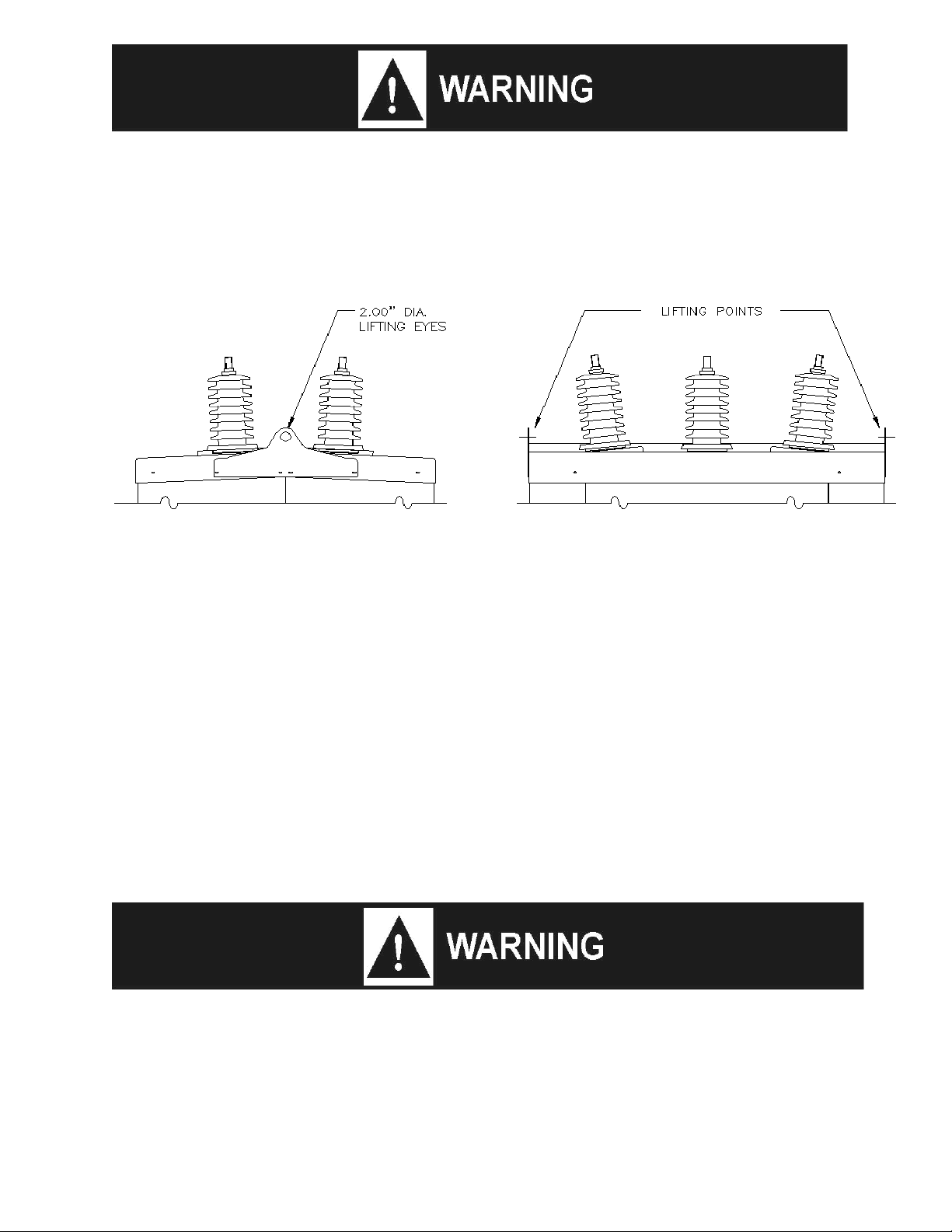
3.2 Handling........................................................................................................................5
3.3 Storage..........................................................................................................................6
4. GENERAL DESCRIPTION.............................................................................................. 6
4.1 High-Voltage Assembly.................................................................................................6
4.2 Housing.........................................................................................................................7
4.3 Magnetic Actuator .........................................................................................................7
4.4 Actuator Controller ........................................................................................................7
5. STANDARD PRODUCTION TESTS................................................................................ 7
6. OPERATION.................................................................................................................... 8
6.1 Closing..........................................................................................................................8
6.2 Opening.........................................................................................................................8
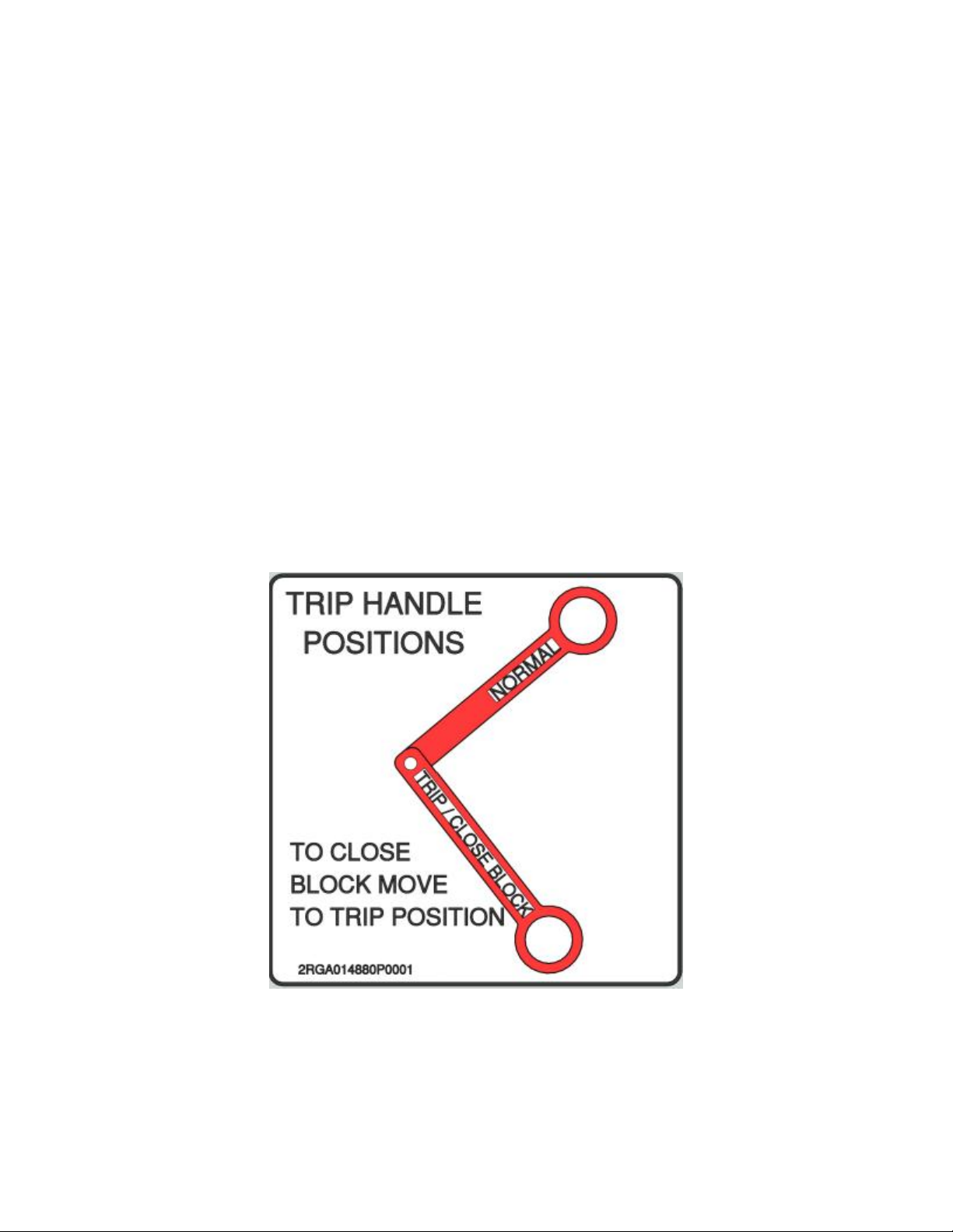
6.3 Manual Trip Handle Operation......................................................................................8
7. OPERATIONAL CHECK PRIOR TO INSTALLATION (ELECTRICAL CLOSE/OPEN).... 9
8. INSTALLATION............................................................................................................... 9
8.1 Mounting .......................................................................................................................9
8.2 Grounding .....................................................................................................................9
8.3 Arrester Protection......................................................................................................10
8.4 Control Power .............................................................................................................10
8.5 Final Inspection...........................................................................................................10
9. INSPECTION, MAINTENANCE AND ADJUSTMENT ................................................... 11
9.1 Maintenance Steps .....................................................................................................11
9.2 High-Pot Test..............................................................................................................12
9.3 Measuring Contact Travel...........................................................................................12
10. 38 kV R-MAG ELECTRICAL SPECIFICATIONS........................................................... 24
10.1 Typical Current Transformer Connections...............................................................26
10.2 Auxiliary Switch Current Specifications.................................................................... 27
10.3 Control Board Voltage Requirements ......................................................................27
10.4 Breaker Nameplate..................................................................................................28
11. RENEWAL PARTS........................................................................................................ 28
12. PRODUCT RECYCLING............................................................................................... 28
APPENDIX A............................................................................................................................. 29

3
Table of Figures
Figure 1 Hazardous Voltage Nameplate...................................................................................... 4
Figure 2 Lifting Detail...................................................................................................................6
Figure 3 Trip Handle Position Sticker..........................................................................................8
Figure 4 Interrupter Assembly 38 kV, 1250 A............................................................................15
Figure 5 Interrupter Assembly 38 kV, 2000 A............................................................................16
Figure 6 Trip Handle..................................................................................................................17
Figure 7 ABB R-MAG - Vacuum Interrupter Electrical Switching Life Curves (31.5 kA) ............18
Figure 8 ABB R-MAG - Vacuum Interrupter Electrical Switching Life Curves (40 kA) ...............19
Figure 9 High Voltage Cabinet Layout.......................................................................................20
Figure 10 Typical Schematic Diagram.......................................................................................21
Figure 11 Typical Outline, 1250 A .............................................................................................22
Figure 12 typical Outline, 2000 A...............................................................................................23
Figure 13 Breaker Nameplate ...................................................................................................28
List of Tables
Table 1 R-MAG 38 kV, 31.5 kA Ratings....................................................................................24
Table 2 R-MAG 38 kV, 40 kA Ratings......................................................................................25
Table 3 Typical Current Transformer Connections....................................................................26
Table 4 Auxiliary Switch Current Specifications......................................................................... 27
Table 5 Control Board Voltage Requirements..........................................................................27
All sales are subject to ABB INC. General Terms and Conditions of Sale.
While every effort has been made to assure accuracy, the information in
this document is subject to change without notice
© Copyright 2012 ABB INC. All rights reserved.

4
Figure 1 Hazardous Voltage Nameplate
1. SAFETY NOTICES
Install the R-MAG®breaker within the design limitations as described on its nameplate and in
these instructions.
Follow your company’s safety procedures and all applicable laws, regulations and standards
whenever the equipment is being installed, operated, maintained and/or repaired.
WARNING:
FOLLOW THE INSTRUCTIONS IN THIS MANUAL AS WRITTEN. ANY FAILURE TO
DO SO MAY RESULT IN DEATH OR SERIOUS BODILY INJURY
This breaker should not be used as the sole means of isolating a high voltage circuit. For the
safety of personnel performing maintenance operations on the breaker or connecting equip-
ment, all components should be electrically disconnected by means of a visible break and
should be securely grounded prior to working in the high voltage or low voltage compartment.
This product is intended to be operated and maintained by qualified persons, thoroughly trained
and knowledgeable of the hazards involved. This publication is written only for such qualified
persons and is not intended to be a substitute for adequate training and experience in the safety
procedures for this device.
WARNING
Detailed descriptions of standard repair procedures, safety principles and service operations are
not included. It is important to note this document contains some warnings and cautions against
some specific service methods that could cause personal injury to service personnel, damage
equipment, or render it unsafe. These warnings do not cover all conceivable ways in which serv-
ice, whether or not recommended by ABB, might be performed or the possible hazardous
consequences of each conceivable way, nor could ABB investigate all such ways. Anyone using
service procedures or tools, whether or not recommended by ABB, must satisfy himself

5
thoroughly that neither personal safety nor equipment safety will be jeopardized by the service
method or tools selected.
All information contained in this manual is based on the latest product information available at
the time of printing. The right is reserved to make changes at any time without notice.
2. INTRODUCTION
These instructions do not attempt to provide the user of this equipment with every possible diffi-
culty that may occur in the application, operation and maintenance of the product. Also, as
improvement in parts and assemblies are made, some parts may differ in appearance as depict-
ed in the illustrations; however, functionality will be equivalent.
The Type R-MAG breaker is a high-voltage, three-phase device incorporating three vacuum
interrupters, gang operated by a magnetic actuator. Together with the optional relaying and
current transformers, the breaker will sense an overload and automatically open.
Satisfactory performance of the breaker is contingent upon correct installation of the breaker,
and adequate maintenance and service of the breaker. Careful study of these instructions will
permit the user to obtain maximum benefit from this device.
3. RECEIVING, HANDLING AND STORAGE
Each breaker is assembled and tested at the factory prior to shipment.
This equipment was packed and shipped in factory new condition. If damage is noted, call the
carrier at once for inspection and request an inspection report. File a formal claim with the carri-
er, supported with paid freight bill, inspection report and invoice. The local ABB Sales Office
must be notified. This must be done within 10 days of receipt or receiver assumes all
responsibility for damage.
3.1 Receiving Inspection
Upon receipt, it is important to inspect promptly to be certain that the correct material has been
received. In case of shortage, immediately notify the local ABB Sales Office.
Check all parts against the shipping list as they are unpacked. Instructions and literature packed
with the breaker should be kept with the unit. The cabinet provides a convenient place to keep
this instruction book, a copy of the schematic, connection diagram and the breaker test report.
Additional copies of these documents may be obtained upon request from the local ABB Sales
Office.
If the breaker is not to be placed in service immediately, it is essential that proper care be exer-
cised in the handling and storage to ensure good operating conditions in the future. (see section
3.3 Storage)
3.2 Handling
The R-MAG breaker comes with two brackets attached to the sides of the cabinet which provide
for lifting the breaker. A two-point lift is recommended using these brackets. (see Figure 2 Lifting
Detail)

6
Breaker has high center of gravity. If the breaker becomes unbalanced during
lifting, there is a risk of death or serious bodily injury.
Figure 2 Lifting Detail
3.3 Storage
For prolonged storage, indoor storage is recommended. If stored outdoors, the cabinet
heaters must be energized to maintain the warranty. The mechanism and control
compartment is equipped with heaters to reduce condensation.
4. GENERAL DESCRIPTION
4.1 High-Voltage Assembly
Do not remove HV covers unless the breaker is visibly disconnected and
grounded, due to the risk of death or serious injury.
The high-voltage section of the R-MAG breaker consists of three individual phase assemblies.
Each phase of the R-MAG consists of a single vacuum interrupter, flexible shunt and operating
rod.

7
4.2 Housing
The doors of the breaker housing are removable and retained by hinge pins. The position
indicator is visible through the rear door. The breaker nameplate showing rating information,
serial number and shop order number is mounted on the side of the housing.
4.3 Magnetic Actuator
The magnetic actuator incorporates a very powerful permanent magnet assembly. When the
armature is in contact with the upper plate, the magnet produces a holding force in excess of
2700 lbs. The actuator connects to the crankshaft through a coupling connected to the upper
end of the actuator shaft. The manual trip is decoupled from the actuator shaft and is controlled
by its own stored spring energy being released against a dedicated lobe on the crankshaft.
The magnetic actuator has no user serviceable parts and therefore no lubrication or mainte-
nance is required. Should an actuator fail to operate, please immediately contact ABB for
service. The permanent magnets inside the actuator are extremely powerful, with the potential
to trap fingers.
4.4 Actuator Controller
The actuator control board in the R-MAG breaker consists of a power supply, position indication,
switching assembly and capacitor charging system. Refer to Appendix A for an overview of the
actuator controller.
5. STANDARD PRODUCTION TESTS
Standard production tests include:
1. Verification of all wiring per connection diagrams.
2. Electrical Operation: Close and trip. Overcurrent response and automatic closing, with
relaying control option.
3. Functional check of all manual controls: Local/remote, non-reclosing, ground fault bypass,
etc.
4. Current Path Resistance Test: Three readings are made on each phase of the breaker using
a Biddle “Ductor”. Typical values do not exceed 150 micro ohms.
5. Voltage Withstand: The complete breaker is tested between live parts and tank, across open
contacts and between phases. In compliance with ANSI C37.09 and IEC, an AC dielectric
with-stand test at 80 kV is performed. Test duration is one minute.
6. Wiring Insulation: The terminal block connections are given an over-potential test of 1800
volts AC to ground (for 1 sec).

8
6. OPERATION
6.1 Closing
In the open position, the magnetic actuator’s armature rests against the bottom plate in the
actuator assembly. The armature is held there by the force developed by the magnet. When the
top coil is energized, the magnetic flux generated is in the same direction as the magnet
assembly. The armature is drawn into the coil and brought into contact with the upper plate. In
this position, the coil is de-energized and the armature is held in position by the magnets alone.
As the armature is drawn into the coil, the operating rod, which is attached to the top guide rod,
moves the moving contact of the vacuum interrupter towards the closed position. The actuator
has more stroke than the vacuum interrupter and the interrupter contacts make contact before
the actuator has completed the stroke. The additional movement of the operating rod after the
contact closing causes the contact pressure spring to compress at the top of the operating rod.
This wipe allows for contact wear in service.
6.2 Opening
When the bottom coil is energized, the magnetic flux opposes the force generated by the
magnet assembly. This reduces the holding force, the armature is released and the coil attracts
the armature to the bottom plate. Once there, it is held open by the magnet.
6.3 Manual Trip Handle Operation
The trip handle for the 38 kV R-MAG has two states: Normal and Trip/Close Block, which are
described below in further detail.
Figure 3 Trip Handle Position Sticker
Normal Position –In the normal position, the external trip handle is up, and normal operation is
possible.
Trip/Close Block Position –When the trip handle is pulled down to this position, the breaker will
be opened and will not close until the handle is returned to the normal position.

9
7. OPERATIONAL CHECK PRIOR TO INSTALLATION
(ELECTRICAL CLOSE/OPEN)
The breaker should be tested for mechanical and electrical operation before delivery to the
installation site. Make the necessary control power connections. Open the door of the low
voltage compartment to observe the mechanical operations. A manual trip handle is provided on
the outside of the cabinet. (see Figure 6 Trip Handle)
Observe the position-indicator located on the front of the actuator cover plate. If the panel is
green, the breaker is open, and if the panel is red, the breaker is closed (on breakers configured
per IEEE standard). To perform a close or open, ensure the “Ready” light is illuminated above
the Close (1) and Open (0) buttons. Press the appropriate button firmly; keeping hands and
loose clothing clear of operating linkages. If the breaker is already open, nothing will happen
when the open button is pressed. If the breaker is already closed, nothing will happen when the
close button is pressed.
Note: In the event of a malfunction or loss of source voltage, the “Ready” light will not be
illuminated.
8. INSTALLATION
The breaker must be vertical, level and securely fastened. Follow your company guidelines and
codes for setting the height of the breaker, securing the frame to the pole or foundation, and
making connections.
8.1 Mounting
The breaker is normally shipped suitable for substation mounting. The following is the recom-
mended installation procedure.
Substation Mounting:
1. With the lifting brackets mounted to the breaker roof, lift the breaker off the pallet and move
into desired position.
2. Bolt the legs to the pad and raise the upper portion to the desired height.
3. Bolt the legs to the sides of the breaker.
4. Install “X” braces on all sides of breaker.
(see Figure 11 Typical Outline, 1250 A)
5. Make sure all hardware is securely tightened.
8.2 Grounding
The breaker cabinet includes a standard NEMA two-hole stainless steel pad on both side
sheets, legs, and on the roof (optional) for grounding. To ensure proper operation of the
actuator controller, the side sheet where the actuator controller is mounted must be grounded to

10
the ground grid. For personnel safety it is recommended that the opposite side sheet is also
grounded. Ground connections should be made using #6 or larger. If there is ground pad is on
the roof, it should also be grounded to the side sheet.
8.3 Arrester Protection
ABB recommends that surge arresters be properly applied in the substation.
8.4 Control Power
Supply the control power as indicated on the wiring diagram. Verify connections for the heaters
before applying power. For breakers not equipped with DIN-Rail style connectors, check all
terminal block connections for proper tightness. For details of the overall control circuit, refer to
the specific wiring diagrams supplied with the breaker.
8.5 Final Inspection
Do not remove high voltage covers unless the breaker is visibly disconnected
and grounded.
After installation has been completed and prior to energizing the breaker, the following points of
inspection are recommended:
1. Ensure the breaker is properly leveled and securely anchored.
2. Make a final check of tightness of all hardware.
3. Check that the heaters work.
4. Verify that all barriers in high voltage compartment are in place (if removed during
inspection)
5. Securely tighten terminal and ground connections.
6. An A/C Hi-Pot test should be performed to verify the vacuum integrity. A successful
withstand indicates satisfactory vacuum integrity. Replace interrupters that fail to maintain
voltage across the open contacts. Please contact the factory for interrupter replacement.
Refer to section 9.2 High-Pot Test for procedure.
7. Make a continuity check, preferably one measuring contact resistance. Measure contact
resistance with suitable equipment rated not less than 100 A. The resistance value should
not exceed 150 micro ohms.
8. Check control cable entrance fittings for tightness.
9. Operate the breaker from the control box to verify normal operation.
10. Secure all doors and ensure proper gasketing for weather, if supplied.

11
11. Ensure that all tools are removed.
12. Confirm that all high voltage test connections have been removed.
9. INSPECTION, MAINTENANCE AND ADJUSTMENT
The R-MAG breaker is an extremely simple device and requires minimal maintenance,
depending on the frequency of operation and local environmental conditions.
The safety and successful functioning of any apparatus or system connected with the breaker
largely depends on the proper and reliable operation of the unit.
9.1 Maintenance Steps
To provide long reliable service, the breaker must have systematic inspections at regular inter-
vals. Operating experience based on environmental conditions, the number of operations, mag-
nitude of current and any unusual operation, will establish a maintenance schedule that gives
assurance of proper breaker reliability. The following check list is a minimum guide:
1. Check the phase assemblies for external damage and clean if contamination is evident.
2. Lubricate wear points and all pins in linkage assemblies with grease (Use only Dow Corning
55 silicone lubricants).
3. Verify that the breaker operates correctly using the electrical controls.
4. An AC Hi-Pot test can be performed to verify the vacuum integrity. Refer to section 9.2
High-Pot Test for procedure. A successful withstand indicates satisfactory vacuum integrity.
Replace interrupters that fail to maintain voltage across the open contacts. Please contact
the factory for interrupter replacement.
5. Contact Resistance: Measure contact resistance with suitable equipment rated not
less than 100 A DC. The resistance value should not exceed 150 micro ohms.
6. Check heaters to verify proper operation.
7. When inspecting breaker, verify torque on current carrying parts are within tolerances:
.500-13 (or 12mm) threaded bus connections……. 65-80 ft-lbs

12
9.2 High-Pot Test
High voltage applied across an open gap in a vacuum can produce X-radiation.
No radiation is emitted when the breaker is closed, since no gap exists. Also,
when the breaker is open to the specified contact spacing in service or tested
within the voltages specified, X-radiation at one meter is below the level of
concern. A danger could exist at voltages above or contact spacing below that
specified on the nameplate.
1. With the breaker in the open position, jumper both sets of three top terminals (bushings 1-3-
5 together and bushings 2-4-6 together). Ground one set of terminals and the housing.
Connect the high voltage to the other set of terminals. See Figure 11 Typical Outline, 2000
Aand Figure 12 Typical Outline, 2000 A for positioning.
2. Stand clear more than one meter from the breaker before energizing the high voltage
source.
3. Do not exceed 64 kV. Test duration is one minute.
4. If internal flashover occurs, isolate the phases and test each one independently to identify
the defective interrupter. Any defective pole assembly must be replaced prior to the breaker
being placed in service.
9.3 Measuring Contact Over-Travel
The desired over-travel (wipe) for 38 kV R-MAG breakers should be within 0.157 in –0.177 in
(4.0 mm –4.5 mm). The following steps must be performed to measure the contact travel.
1. The faceplate from the mechanism covers one of the rod’s ends. Remove the front panel to
access the rod.

13
2. Connect the transducer to the rod’s end as shown below:
3. Connect the transducer to the motion analyzer. ABB utilizes a Kocos –ACTAS P14:
4. Connect the AMP meter to the actuator coil cables:

14
5. Connect the Kocos to the breaker contacts/bus:
5. If the result is different from the suggested range of 0.157 in –0.177 in (4.0 mm –4.5 mm),
turn the pushrod’s end clockwise to increase wipe, or counter-clockwise to decrease wipe,
depending on the adjustment needed to achieve a measurement within the specified range.

15
Figure 4 Interrupter Assembly 38 kV, 1250 A

16
Figure 5 Interrupter Assembly 38 kV, 2000 A

17
Figure 6 Trip Handle

18
Type R-MAG, 38kV, 2000A, 31.5kA, 200kV BIL
Type R-MAG, 38kV, 1250A, 31.5kA, 200kV BIL
Figure 7 ABB R-MAG - Vacuum Interrupter Electrical Switching Life Curves (31.5 kA)
10
100
1000
10000
100000
0.1 1 10 100
Current (kA, rms)
Life in Number of Operations
10
100
1000
10000
100000
0.1 1 10 100
Current (kA, rms)
Life in Number of Operations

19
Type R-MAG, 38kV, 40 kA
Figure 8 ABB R-MAG - Vacuum Interrupter Electrical Switching Life Curves (40 kA)

20
Figure 9 High Voltage Cabinet Layout
Table of contents
Other ABB Industrial Equipment manuals
Popular Industrial Equipment manuals by other brands

Zaber
Zaber X-LRQ-DEC Series user manual

eta
eta ETAbox user manual

Minebea Intec
Minebea Intec PR 6246/12 installation manual

RIDGID
RIDGID 918 Roll Groover manual

Innotech
Innotech INNOTECH BEF 401-10 Instructions for installation and use

Spirax Sarco
Spirax Sarco UTD30 Series Installation and maintenance instructions

Maschinenfabrik Reinhausen
Maschinenfabrik Reinhausen VACUTAP VM-Ex operating instructions

Spudnik
Spudnik 1200 parts manual

Nord Drivesystems
Nord Drivesystems B 1000 Manual with installation instructions

SCHUNK
SCHUNK AGE-XY 63 Assembly and operating manual

Western Global
Western Global ECW105 manual

DÖRR
DÖRR EcoFlow LPF P Operation manual