Hayward Ultra-Pro LX Series User manual

IS-2290-02-HC
HAYWARD Hi-Performance SELF-PRIMING PUMPS
INSTALLATION AND OPERATING INSTRUCTIONS
GENERAL TIPS ON PUMP INSTALLATION
For best pump performance, locate the system below
the pool water line and as close to the pool as possible.
If you own an above ground pool please see Note: NSPI-
4 Article V, for safe and proper installation of the
equipment package. Make sure suction joints are tight.
Suction pipe should be as large or larger than discharge
pipe.
Damp, non-ventilated locations should be avoided.
Motors require free circulation of air to aid in cooling.
Insure that the electrical supply available agrees with the
motor's voltage, phase and cycle, and that wire size is
adequate for the HP/KW rating and distance from the
power source. Motor must always be properly grounded.
If cord connected, use only a properly grounded outlet.
Electrical circuits should be protected by proper size
ground fault circuit interrupter (GFCI).All electrical wiring
should be performed by qualified personnel and must
conform to local codes and regulations.
STARTING AND PRIMING INSTRUCTIONS
Fill strainer/housing completely with water. Never
operate the pump without water. Water acts as a coolant
and lubricant for the mechanical shaft seal.
Open all suction and discharge lines and valves, as well
as air bleed (if available) on filter. (The air that is to be
displaced from the suction line must have some place to
go).
Turn on power and allow a reasonable time for priming.
Priming time depends on suction lift and length of
suction piping. If pump will not start, or will not prime, see
TROUBLE SHOOTING GUIDE on back page.
Note: NSPI-4 Article V, standard for above ground and
on ground pools, advises that components such as the
filtration system, pumps and heater be positioned so as
to prevent their being used as a means of access to the
pool by young children.
Your Hayward Ultra-Pro LX pump has been quality-built
and engineered to give you many years of efficient,
dependable service. The non-conductive, corrosion-proof
motor housing provides protection from the elements and
insulates the electrical motor parts from outside contact.
The advanced design reduces operation and maintenance
to simple, common-sense procedures.
MAINTENANCE
1. Clean strainer basket regularly. Do not strike basket
to clean. Inspect strainer cover gasket regularly and
replace as necessary.
2. Hayward pumps have self-lubricating motor bearings
and shaft seals. No lubrication is necessary.
3. Keep motor housing clean. Insure air vents are free
from obstructions, debris, etc.
4. Occasionally, shaft seals must be replaced, due to
wear or damage. See instructions
STORAGE/WINTERIZING
Pump and motor must be protected from freezing. Shut
off all electric power. Disconnect cord/electrical
connections and plumbing connections. Drain
thoroughly and clean out any debris. Store pump and
motor in a dry, well ventilated room.
HAYWARD POOL PRODUCTS CANADA, INC.
2880 PLYMOUTH DRIVE, OAKVILLE, ONTARIO L6H 5R4 • (905) 829-2880
® Hayward Pool Products Canada, Inc. – Licensee

PART NUMBER
Ref. DESCRIPTION No. MODEL MODEL
No. Req'd SP2290 (T) SP-2295 (T) (ET)
1Strainer Cover 1 SP1500D2A SP1500D2A
2Strainer Cover w/O-ring 1 SP1500P SP1500P
3Basket 1 SP1500LX SP1500LX
4Strainer Housing 1 SP1500CP SP1500CP
5Drain Plug (optional) – SP1700FG SP1700FG
6Drain Plug w/Gasket 1 SP1700FG SP1700FG
7O-ring 1 SP1500W SP1500W
8Bolt, No.10-24 Hex. Head 8 SP1500N2 SP1500N2
9Housing Cover 1 SP1580BP SP1580BP
10 Housing O-ring 1 SP1580Z1 SP1580Z1
11 Impeller 1 SP1500E SP1500F
12 Seal Assembly 1 SP1500KA SP1500KA
13 Pump Housing 1 SP1580AAP SP1580AAP
14 Nut, No. 10-24 Hex. 8 SP1500Y2 SP1500Y2
15 Shaft Sleeve 1 SP1500Q2 SP1500Q2
16 Motor 1 SP1509ZIUF SP1514ZIUF
17 Shroud 1 SP2090B SP2090B
18 Motor Housing 1 SP2090A SP2090A
19a Timer End Cover (Mechanical) (T) 1 SP1500TI SP1500TI
19b Timer End Cover (Electronic) (ET) Optional – SP2090CET
20 Motor-To-Housing Bolt 4 To order, specify manufacturer, HP and Model No.
21 Elevated Mounting Base Optional SP2601C SP2601C
22 Motor End Cover Optional SP2090C SP2090C
23 Switch Assembly Optional EC1325 EC1325
24 Power Cord 1 SP1550WA7C SP1550WA7C

ULTRA-PRO LX PUMP MECHANICALTIMER MODULE INSTRUCTIONS
Your integrated timer module is preprogrammed to operate your filtration system for nine
(9) hours – one five hour period and one four hour period during the day.
All you have to do is set the correct time (Step 2) and plug in. If you prefer customizing
your settings, follow Steps 1-5.
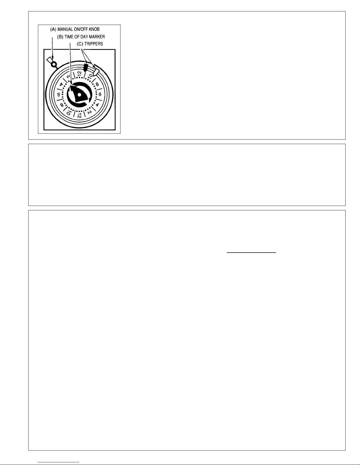
To Set Timer: (See Illustration)
1. To remove ON/OFF trippers, pull out completely from timer dial and then insert ON (red)
and OFF (white) trippers (C) into dial at desired ON and OFF times (if only one setting is
desired, remove the extra ON and OFF tripper from the dial).
2. Turn dial CLOCKWISE one or more complete revolutions until the exact time-of-day is
to the time-of-day marker (A).
3. FOR EARLY ON OR OFF OPERATION: Turn manual knob (B) counter clockwise to
desired ON or OFF position. Timer will follow next scheduled automatic operation.
4. Close cover after setting.
5. Plug in Pump/Timer unit.
IN CASE OF POWER FAILURE, RESET TIMER, (SEE STEP 2)
WARNING: THIS SWIMMING POOL PUMP TIMER IS INTENDED FOR USE ON
A.O. SMITH, 115 VOLT MOTORS ONLY UP TO 16 FULL LOAD AMPS.
01. Turn off power and unplug power cord. Remove pump
and motor assembly from piping system. (If optional
elevated mounting base was installed, pump assembly
can be disengaged from elevated base by depressing
spring catch on top of base, and sliding pump assembly
out to the rear).
02. Remove motor housing end cover by removing two (2)
screws. Carefully pull cover away from motor and
disconnect wires from motor terminals.
03. Remove pump housing cover (with strainer attached)
by removing the eight (8) housing bolts and nuts which
fasten housing cover to pump housing. The impeller is
now exposed.
04. To remove impeller, insert screwdriver in slot at end of
motor.* Hold screwdriver so as to keep shaft from
turning, and rotate the impeller in a counterclockwise
direction. The spring portion of the seal assembly is
now exposed.
05. Note carefully the position of the spring seal and pull it
off the impeller.
06. To remove the stationary (ceramic seat) part of the seal
assembly:
a. Loosen the four (4) motor securing bolts and
disengage the motor, with motor housing in place,
from the pump housing.
b. With motor removed, press the clear plastic and
ceramic seat assembly out of the pump housing
recess. If tight, tap lightly from the "motor" side.
07. Clean and lubricate the impeller hub shaft and pump
housing seal recess. Use silicone or Jack's No. 327 O-
Ring lube. Gently wipe the polished face of the new
ceramic seat with a soft, dry cotton cloth.
08. Press the new spring portion of the assembly onto the
impeller, black polished surface facing away from the
impeller.
09. Be sure black rubber O-Ring is in place on cut ridge of
clear plastic seat retainer. Press plastic retainer, with
ceramic seat inside, into recess of pump housing - O-
Ring end first. Seat the assembly firmly and evenly,
using finger pressure.
10. Carefully insert the motor shaft thru the seat assembly,
and secure motor and motor housing to pump housing
with four (4) motor securing bolts. (Be sure motor
housing mounting bracket is positioned properly.
11. Screw the impeller, with spring seal, onto the motor
shaft, hand tight, by turning clockwise.
12. Clean housing O-Ring (replace if necessary) and fasten
housing cover to pump housing with eight (8) bolts and
nuts. Tighten bolts and nuts alternately and evenly.
13. Reconnect electric wires from power cord and timer to
pump motor terminals. Both white wires to line 2; both
black wires to A; red timer wire to line 1. Ground wire to
ground screw on motor. Replace cover and secure with
two (2) screws.
14. Reconnect pump to piping system. Be sure to fill
strainer with water before restarting.
SEAL CHANGE INSTRUCTIONS
Exercise extreme care in handling and installing the new seal and seat assembly.
The lapped and polished surfaces may easily be damaged by dirt or scratching.
For safety, all service must be performed with all power shut off.
ELECTRONICTIMER MODULE INSTRUCTIONS
Your integrated timer module is designed to be programmed to your filtration need, with four (4) possible settings.
Settings:
Setting 1 - Pump runs 24 hours continuously - (1 beep)
Setting 2 - Pump runs 18 hours and is off for 6 hours - (2 beeps)
Setting 3 - Pump runs 12 hours and is off for 12 hours - (3 beeps)
Setting 4 - Pump runs 6 hours and is off for 18 hours - (4 beeps)
When the pump is switched from position “off” to “program” a beep sound
is heard. This allows the pumps to differentiate between settings.
To Set Timer:
1. Move switch from “off” to “program” to “off” produces 1 beep
2. Move switch from “off” to “run”
3. Repeat above 2 steps according to your choice of setting
If a power failure occurs: After the power is restored, the timer will
automatically default to the programmed mode, adding the length of time
of the power failure.
*For A.O. Smith Motors: Carefully apply wrench to flat on rear motor shaft to hold shaft from turning.

TROUBLE SHOOTING GUIDE
A. MOTOR WON'T START
1. Check for improper or loose connections,
open switches or relays, blown circuit
breakers or fuses.
2. Manually check rotation of motor shaft for free
movement and lack of obstruction.
B. MOTOR CUTS OUT – Check for:
1. Wiring, loose connections, etc.
2. Low voltage at motor (frequently caused by
undersized wiring.
3. Binding and overload. (Amperage reading)
NOTE: Your Hayward pump motor is equipped with
Automatic Thermal Overload Protection. The
motor will automatically shut off, under normal
conditions, before heat damage build-up, due
to an improper operating condition, can
occur. The motor will auto-restart when safe
heat level is reached.
C. MOTOR HUMS BUT DOES NOT START
– Check for:
1. Centrifugal switch stuck in open position.
2. Binding of motor shaft.
D. PUMP WON'T PRIME
1. Make sure pump/strainer housing is filled with
water, and that cover O-Ring is clean and
properly seated. Make sure strainer cover is
locked firmly in position.
2. Make sure all suction and discharge valves
are open and unobstructed, and that pool
water level is above all suction openings.
a. If pump develops a vacuum, check for blocked
suction line or strainer, or air leak in suction
piping.
b. If pump does not develop a vacuum and pump
has sufficient "priming water":
1. Tighten all bolts and fittings.
2. Check voltage to make sure pump is up to
speed.
3. Open pump and check for clogging and
obstruction.
4. Remove and replace shaft seal.
E. LOW FLOW – Generally, Check for:
1. Clogged or restricted strainer or suction line;
undersized pool piping.
2. Plugged or restricted discharge line of filter
(high discharge gauge reading).
3. Air leak in suction (bubbles issuing from return
fittings).
4. Pump operating underspeed (low voltage).
5. Plugged or restricted impeller.
F. NOISY PUMP – Check for:
1. Air leak in suction causing rumbling in pump.
2. Cavitation due to restricted or undersized
suction line and unrestricted discharge lines.
Correct suction condition or throttle discharge
lines, if practical.
3. Vibration due to improper mounting, etc.
4. Foreign matter in pump housing.
5. Motor bearings made unserviceable by wear,
rust, or continual overheating.
SERVICE AND REPAIRS
Consult your local authorized Hayward dealer or service center.
No pumps or motors may be returned directly to the factory without the
express written authorization of Hayward Pool Products Canada, Inc.
ELECTRICAL GUIDE – 60 CYCLE MOTORS – SINGLE PHASE
MOTOR
HP KW
1 .75
1 1/2 1.12
VOLTS Circuit Breaker
RATING – AMPS RECOMMENDED
WIRE SIZE 0-50', 0-15m
115 20
20
No. 12
No. 12115
This manual suits for next models
5
Table of contents
Other Hayward Power Pump manuals