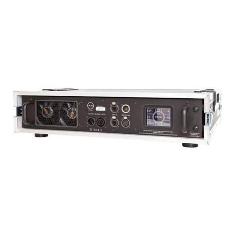
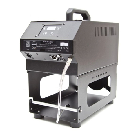
HazeBase ultimate User manual

Instruction manual
www.hazebase.com

ultimate
Scope of delivery
1 ultimate
1 5l empty canister
1 tank cap with quick coupling
1 fluid hose with quick coupling and nozzle
1 power cable with TrueOne plug
1 tank holder
1 instruction manual
Please check that the delivery is complete.
1

ultimate
Table of Content
1. Introduction 3
2. Safety instructions 4
3. Description of the parts 5
4. Preparation 6
4.1 Selection of the location 6
4.2 Changing the canister 6
4.3 Hose cover 6
5. Fog fluids 6
6. Working with the ultimate 7
6.1 Control panel of the ultimate 7
6.2 Operating in stand-alone mode 8
6.3 Operation via DMX512/RDM 8
6.4 Operation via the AUX input 9
6.5 Operation via Modbus RTU 9
6.6 Operation via cable remote control (option) 10
6.7 Operation via radio remote control (optional) 11
6.8 Operation using the internal timer 12
7. Menu options items 13
7.1 Setting the fluid used 13
7.2 Setting the communication protocol of the XLR sockets 13
8. Care and maintenance 14
9. Troubleshooting 15
10. Technical data 16
11. Guarantee conditions 17
A Annex 19
2

ultimate
1. Introduction
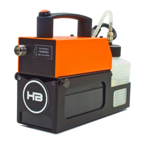
The ultimate is a powerful fog machine with unique direct heating. It requires only the
shortest possible heating time (2 sec.) and also has a stainless steel housing with IP64
protection class.
The possible applications are varied and range from theme parks and fire drills to
large stages.
3

ultimate
2. Safety instructions
Very hot steam emerges from the mist outlet. Caution: Danger of burns !
During the fogging process, very hot fluid droplets may occasionally escape
from the fog outlet. Therefore, no persons or heat-sensitive objects may be
located within 1.5 m of the fog outlet.
Never handle the mist outlet during operation or when activated.
The appliance must be installed in a location that is not heat-sensitive. Keep
a minimum distance of 60 cm to flammable, combustible and heat-sensitive
objects.
The fog fluid used contains a glycol which burns with a slightly bluish,
almost invisible flame. Therefore, never fog into strong ignition sources
such as open fire.
Never open the appliance connected to a power source.
During operation, isolated hot fluid droplets may escape. Care should
therefore be taken to ensure that these cannot become a danger to people.
Maintain a safety distance of 3m from the mist outlet nozzle.
Do not ingest the fog fluid and keep it away from children. In case of eye
contact, rinse with plenty of water. If inadvertently taken, consult a doctor.
Spilled or splashed fluid can cause slipping. Pick up fluid and dispose of it
according to regulations.
Do not allow visibility to fall below 2m, you are responsible for people
moving around in the fogged room.
The mist produced can trigger smoke detectors.
The method used here to produce artificial fog is largely harmless and is used
worldwide in the entertainment sector. We are not aware of any case in which a
healthy person would have been harmed by using this artificial fog. Nevertheless,
we recommend that sick persons or persons with previous respiratory tract
damage or allergies avoid contact with artificial fog!
4

ultimate
3. Description of the parts
Front view
Rear view
5
Handle
Fog nozzle
Hose cover
Tank holder
Fluid canister
Membrane
keyboard with
OLED Display
Fluid Inlet (1)
DMX/RDM,
Modbus and
radio interface
(2)
Remote control Input (3)
Case ventilation
Power supply

ultimate
4. Preparation
4.1 Selection of the location
The location where the ultimate must be operated
●have good ventilation
●be free of vibrations and shocks
●consist of a non-flammable floor space
●be far enough away from easily flammable objects
●have an ambient temperature between 5°C and 45°C
4.2 Changing the canister
1. Release the plug-in sleeve from the quick coupling by pressing the locking
button
2. Remove the canister safety device by pressing the locking pins
3. Remove the canister from the tank holder
4. Unscrew the tank cap from the empty canister and screw it onto a new or
full canister.
5. Slide the canister back into the tank holder.
6. Refasten the canister lock to the tank holder
7. Replace the connector sleeve in the fuel filler cap.
4.3 Hose cover
The ultimate is equipped with a hose cover (100mm). Please only use hoses that can
cope with the temperatures. The hose may only be pushed onto the adapter a
maximum of 50mm, so that the fog nozzle is surrounded by enough fresh and cold
air.
5. Fog fluids
Two different fluids are available for the ultimate (see chapter 7.1)
base*F is a very long lasting fluid
base*R is a very fast dissolving fluid
The type of fluid selected must be set on the unit, otherwise the fluid may
not evaporate correctly.
6

ultimate
6. Working with the ultimate
The ultimate is a fog machine with a strong output. From small fog clouds to dense,
room-filling fog, any desired effect can be achieved. The fine adjustment of the pump
allows fog output settings between 1% and 100%.
6.1 Control panel of the ultimate
The ultimate is operated using the four keys (Menu, Minus, Plus, Confirm) and the
OLED display. In the corners of the display are the menu fields, in the middle the
value field, which shows the value of the selected menu field. The individual menus
are selected by turning the menu key counter-clockwise. The corresponding value can
then be changed with the plus and minus keys and then saved with the confirmation
key.
7
Menu Fields
Confirmation button
Plus buttonMinus key
Value field
Menu key

ultimate
6.2 Operating in stand-alone mode
The simplest case of control is the stand-alone mode. For this purpose, the pump
value is set to the desired value and the confirmation key is pressed. The machine
immediately starts to heat up the heating element and starts the fogging process.
The pump value can also be changed during the fogging process.
Press the confirmation key again to stop the fogging process. A reheating process
flushes out all fluid residues still in the heating element. The heating is then switched
off again.
6.3 Operation via DMX512/RDM
When operating via DMX512, the
XLR input (2) must first be set to
DMX (see chapter Options).
As shown, "DMX" appears in the
upper right-hand menu field. The
DMX address can be changed with
the plus and minus keys and must
then be saved with the confirmation
key.
If a valid DMX signal is present, this is indicated by "active" in the top center. The
currently read pump value can be displayed by selecting the pump menu item. If the
value received is greater than zero, the ultimate starts the fogging process and stops
it at zero again.
Via RDM the ultimate is both configurable (DMX address) and readable (error or
temperature data). Furthermore, a firmware update can be carried out via this RDM
input.
8
DMX signal DMX mode

ultimate
6.4 Operation via the AUX input
The ultimate has an aux-input (3), with which the
machine can be controlled via 0-10V. The pin
assignment of this input is shown on the right. Pin 1
and 4 are used to supply possibly connected
consumers (12V, max. 100mA). A voltage between
1V and 10V can be applied to pin 2. From a voltage
of 1V the fogging process starts. The pump value is adjusted according to the applied
voltage. 10V at the input corresponds to the maximum set pump value. Below 1V the
machine is switched off again.
Pin 3 is an output (24V, 50mA) that indicates whether the machine has a fault.
6.5 Operation via Modbus RTU
When operating via Modbus RTU, the XLR input (2) must first be set to Modbus (see
chapter Options). The interface is designed as RS485 half-duplex connection.
The communication parameters of the connection can be set in the "Modbus"
submenu. First the menu item Modbus must be selected. “Enter" is displayed in the
value field. The sub-menu for Modbus is entered with the confirmation key.
9

ultimate
In the Modbus submenu, the menu fields are replaced. The address of the unit can be
set at the top left. The baud rate of the communication is set at the bottom left and
the data width, parity and stop bits at the bottom right. The settings are made in the
same way as in the main menu.
To exit the sub-menu, select the menu item "exit" and confirm with the confirmation
key.
In the appendix you will find the definitions of the registers that are necessary for
programming the PLC.
6.6 Operation via cable remote control (option)
When operating via cable
remote control, the XLR input
(2) must first be set to Remote
(see chapter Options).
When the wired remote control
is plugged in, the ultimate
automatically recognizes that
an analogue wired remote
control has been plugged in.
On the cable remote control
there is a switch and a potentiometer for adjusting the pump value.
10

ultimate
6.7 Operation via radio remote control (optional)
When operating via radio
remote control, the XLR input
(2) must first be set to Remote
(see chapter Options).
When the radio remote control
is plugged in, the ultimate
automatically recognizes that a
radio remote control has been
plugged in.
Up to 60 different hand transmitters can be taught on the machine. To do this, the
sub-menu "Remote" must first be selected.
In the Remote submenu, the
menu fields are replaced. The
channel (key on the handheld
transmitter) can be selected in
the top left-hand corner. A
new remote control transmitter
is tuned in at the bottom left
and the tuned-in remote
controls are deleted at the
bottom right.
A new handheld transmitter is trained as follows. First select the menu item add and
confirm it with the confirmation key. "Adding" now appears at the bottom left. The
machine is now waiting for a valid radio signal. To do this, press any key on the
hand-held transmitter. The teach-in process is now complete and "add" appears
again at the bottom left. Afterwards you can still select the key and save it.
To delete the handheld transmitters which have already been tuned in, select the
menu item "del" and confirm it. "Deleting" now appears in the bottom right-hand
corner. The deletion process is now in progress. After the deletion process has been
successfully completed, the display returns to "del".
To exit the sub-menu, select the menu item "exit" and confirm with the confirmation
key.
11

ultimate
6.8 Operation using the internal timer
To set and activate the internal
timer, you must first switch to
the Timer sub-menu.
Here too, the menu fields are
changed accordingly. In the
upper left corner you can now
set the pump value that is used
in timer mode. At the bottom left
the waiting time can be set in
0.1 minute (6 sec.) steps. Similarly, the fogging time can be set in steps of seconds at
the bottom right.
To activate the timer, you can press the confirmation key during either the wait time
or the fog time. This enables or disables the timer. Depending on the selected menu
item, the timer starts with the waiting time or the fogging time.
The pump value can still be changed even when the timer is activated.
If you exit the "Timer" sub-menu, the timer is also deactivated again.
12

ultimate
7. Menu options items
In the "options" sub-menu, you can set the type of fluid used and also select the
protocol of the XLR sockets.
7.1 Setting the fluid used
After activating the submenus,
the menu fields in the corners
are changed. The menu item
"Fluid" now appears at the
bottom left and the menu item
"Input" at the bottom right.
In the menu item "Fluid" you
can choose between the fluid
type base*F and base*R. Set the
desired fluid type and confirm this with the confirmation key.
ATTENTION ! The fluid types have different boiling points, so that a wrong
setting can lead to spitting of hot fluid drops or to unpleasant odors when
nebulizing. Therefore, always set the type of fluid used.
7.2 Setting the communication protocol of the XLR sockets
In the menu item "Input", you can select the communication protocol of the XLR
sockets. The following protocols can be selected here:
DMX/RDM
Modbus
Remote (cable or radio)
Please select the desired protocol and confirm it with the confirmation key.
13

ultimate
8. Care and maintenance
●Avoid running the ultimate without fluid. Otherwise, the pump will run dry.
●Avoid overheating the unit due to direct sunlight or direct spotlight. The
permissible ambient temperature can be found in the technical data.
●Immediately wipe up any escaped fluid.
●Check the suction strainer in the tank from time to time. Clean it or replace
it.
●If the same fluid canister is used frequently, you should rinse it thoroughly
before each filling with fresh fluid. In this way you avoid contamination.
●The tank holder can be unscrewed for permanent installation. Please note:
The difference in height between the external canister and the machine
must not exceed 1.5 meters, otherwise the pump will not be able to suck in
the fluid).
●If necessary, clean the surface of the device with a suitable, solvent-free
cleaning agent
●Check the seals on the machine from time to time. Defective seals or
housing parts can result in the machine no longer having moisture
protection (IP64).
●PLEASE NOTE: The vaporizer of our foggers does NOT need to be
cleaned! Cleaning liquids that are available on the market can damage the
vaporizer! In this case the guarantee becomes void.
14

ultimate
9. Troubleshooting
The ultimate does not fog
Check external control
Check power source
Check fluid quantity
Check the connection on the fluid tank for leaks
Check suction strainer in the tank for contamination
Check fluid hose and connector for leaks
The ultimate suddenly switches off
The temperature inside the appliance is too warm. Remove the external
heat source. The unit switches on again after it has cooled down.
The ultimate hums loudly when fogging
The pump runs dry. This must be avoided at all costs.
Refill fluid
Check hose and coupling, if necessary re-engage.
The ultimate shows the error message "machine too hot" in the display
The temperature inside the unit is too high. After cooling down, the error
disappears again.
The ultimate shows the error message "vaporizer faulty" in the display
The vaporizer module has an error or no longer responds. In this case the
unit must be sent for service.
15

ultimate
10. Technical data
16
Device type
Directly heated evaporator fog machine
Performance
200-250V~, 50-60 Hz, 3300 W
(PowerCON TRUE1)
Heating time
approx. 2 seconds
Fluid consumption
up to 90ml/min
Tank capacity
5 liters
Operation
1.3" OLED display, membrane keyboard
Interfaces
5pin XLR In/Out, Aux-In (Analog 0-10V)
Supported Protocols
DMX512, RDM, Modbus RTU
direct SPS control
Control
DMX, analogue, integrated timer, stand alone
Accessories (option)
Radio remote control, cable remote control
Protection class
IP64
Fluid types
base*F (long lasting)
base*R (fast resolution)
Dimensions (LxWxH)
487 x 210 x 235 mm
(height with tank holder 388mm)
Weight
12,5 kg
Ambient temperature
+5°C to 45°C

ultimate
11. Guarantee conditions
For the purchased fog machine ultimate hazebase provides a guarantee according to
the following conditions:
1. We will remedy free of charge in accordance with the following conditions (nos.
2 to 6) any damage or defects in the device which are demonstrably based on
factory defects if they are reported to us immediately upon discovery and within
24 months of delivery to the end user. A guarantee obligation is not triggered by
minor deviations from the nominal quality, which are insignificant for the value
and usability of the device, by damage from the effect of water and generally
from abnormal environmental conditions or force majeure.
2. The guarantee is provided in such a way that defective parts are repaired free of
charge or replaced by faultless parts at our discretion. Devices for which a
warranty service is claimed with reference to this warranty are to be handed
over to us and sent free of charge.
The proof of purchase with purchase and/or delivery date must be presented.
Replaced parts become our property.
3. The warranty claim expires if repairs or interventions are carried out by persons
who are not authorized by us to do so or if our devices are fitted with
supplementary or accessory parts which are not matched to our devices.
Furthermore, the warranty claim expires if a fog fluid other than the original
hazebase fog fluid is used. If the units are sent to us without prior removal or
emptying of the fluid canister, the warranty will also expire, as well as in the
case of proven disregard of the operating instructions or errors due to improper
treatment/handling as well as damage due to the use of force.
4. We do not grant any performance claims for components or component groups
that are subject to natural wear and tear or normal wear and tear. In particular,
all fluid-conveying parts such as pumps and heating elements are deemed to be
wearing parts. A goodwill regulation will be checked in each individual case.
5. Warranty services do not extend the warranty period, nor do they initiate a new
warranty period. The warranty period for installed spare parts ends with the
warranty period for the entire device.
17

ultimate
6. If a damage or defect cannot be remedied by us, or if we refuse or unreasonably
delay the remedy, we will, at the request of the end user, within 6 months of the
purchase/delivery date either
a. replacement delivered free of charge or
b. the reduced value is reimbursed or
c. take back the equipment against reimbursement of the purchase price, but not
exceeding the usual market price.
7. Any further or other claims, in particular those for compensation for damages
incurred outside the device, are excluded - unless liability is mandatory by law.
18

ultimate
AAnnex
19
Table of contents
Other HazeBase Fog Machine manuals
