Protect 800i C User manual
PROTECTGLOBAL.COM
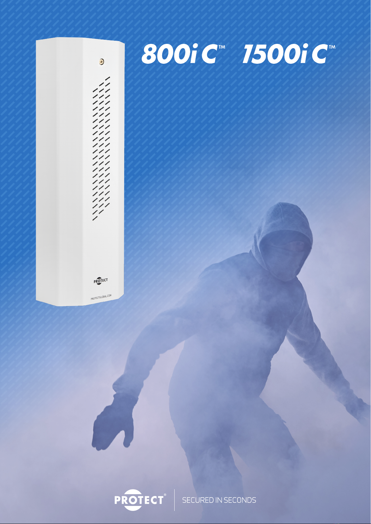
PROTECT 800i C™ / 1500i C™ is designed to protect the most common
premises. Private homes and garages, shops and stores, offices, and
small and medium-sized warehouses.
The two new Fog Cannons™ are built on the same platform, but one
is sized for several cubic meters of fog and can fire for longer than
the other. Many of the specifications are otherwise similar.
INSTALLATION MANUAL
EN - Version 1.0
Item no.: 22069_0001EN

PROTECT 800i C™I 1500i C™
2 I SECURED IN SECONDS
EN
INSTALLATION MANUAL
Content
1. Before you begin . . . . . . . . . . . . . . . . . . . . . . . . . . . . . . . . . . . 3
2. Safe instructions and ‘best practice’ . .................... 4
3. Mounting . ....................................... 6
4. Connection and settings . ............................. 7
5. Test and hand over ................................. 12
6. Error messages and troubleshooting . .................... 14
7. Warnings ........................................ 17
8. Consequencesoftheuseofunauthorizeduidin
PROTECT Fog Cannons®.............................. 18
9. Warranty terms and exceptions . . . . . . . . . . . . . . . . . . . . . . . . 18
10.Approvalsandcertications . ........................ 19
11. APPENDIX
Manual for PROTECT IPCard™ ......................... 23

PROTECT 800i C™I 1500i C™
3 I SECURED IN SECONDS
1. Before you begin
1 2
3 4
Start by reading this manual - the included quick
guide cannot stand alone.
By now you should have completed our installation
course. That may be a requirement.
Read more at www.protectglobal.com/e-learning
Always use IntelliSuite™ V.2.50.0.0 and
IntelliConnector™ for the best, safest and fastest
installation with documentation.
For technical support, please contact the place
where you purchased the Fog Cannon™ machines
or nd help in this manual.
INSTALLATION MANUAL
PROTECT 800i C™I 1500i C™
4 I SECURED IN SECONDS
2. Safe instructions and best practice
INSTALLATION MANUAL
5 6
8
7b
9
Min. 10 cm
Min. 10 cm
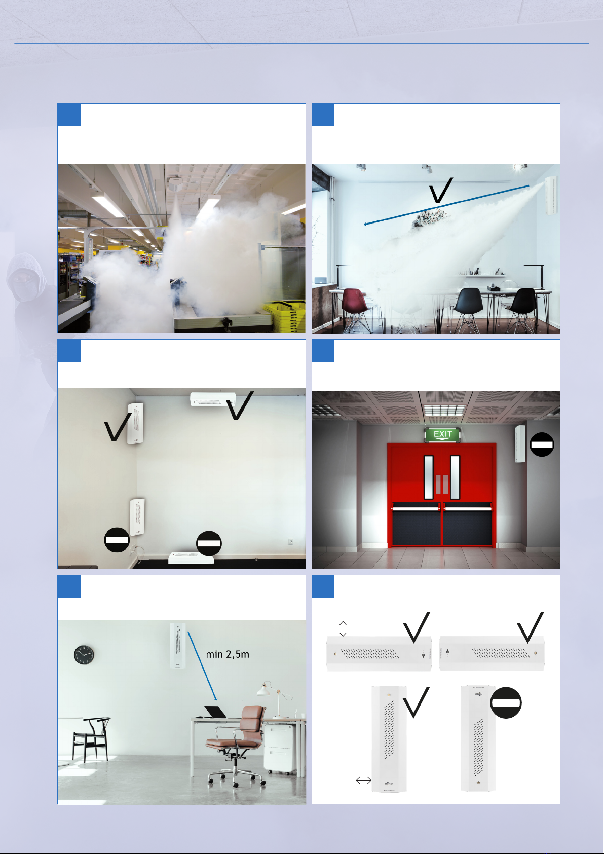
To ensure the best possible coverage the fog
needs free passage.
The fog machine must be placed to ensure
immediate coverage of possible access points.
Avoid covering escape routes with security fog.
For horizontal mounting, place the fog machine as
shown in the picture
Min. installation distance from objects – 2.5 m.
7a Reduce the risk of sabotage by placing the Fog
Cannon™ as high as possible. At the same time, pro-
per placement provides the most effective security.

PROTECT 800i C™I 1500i C™
5 I SECURED IN SECONDS
INSTALLATION MANUAL
10
12 13
Z X
Y
Measurements for installation of the fog machine.
IMPORTANT! Disconnect power to the machine before
removing the metal case.
Avoid unintentional fog emission – remove the fluid
container during installation and service and/or press
the service button.
11 Minimum safety distance is 35 cm for people and
objects. Do not look directly into the nozzle at a
short distance - risk of scalding!
PROTECT 800i CTM
650 mm
190 mm
150 mm
13,5
PROTECT 1500i CTM
650 mm
190 mm
170 mm
18,5
X
Y
Z
KG

PROTECT 800i C™I 1500i C™
6 I SECURED IN SECONDS
3. Mounting
INSTALLATION MANUAL
14 15
Unpack the Fog Cannon™ from the cardboard box
and remove the metal case.
Now remove the mounting plate on the Fog Cannon™.
Start by disassembling the uid container.
16
18 19
17
Place the Fog Cannon™ on the attached mounting
plate. Important! Remember to screw the safety
screw back in before you continue working.
Cabling of PROTECT 800i C™ / 1500i C™.
One cable to the alarm system, and the other
cable to 115/130/230V power.
When mounting in corners, included corner brackets
must rst be screwed onto the back plate of the
machine.
Place and fasten the mounting plate to the wall or
ceiling with the necessary fastening to the base.
Remember to bring the cables from the wall/
ceiling out through the hole in the back of the plate.

PROTECT 800i C™I 1500i C™
7 I SECURED IN SECONDS
4. Connection and settings
Printed circuit board (PCB)
Voltage
PROTECT 800i C™PROTECT 1500i C™
230 V - 50 Hz 230 V - 50 Hz
Effect
PROTECT 800i C™PROTECT 1500i C™
1050 W 1350 W
Standby consumption after heating up
PROTECT 800i C™PROTECT 1500i C™
44 W 56 W
Standby consumption when heat is disabled
PROTECT 800i C™PROTECT 1500i C™
5-10 W 5-10 W
INSTALLATION MANUAL
PROTECT 800i C™I 1500i C™
8 I SECURED IN SECONDS
COM.
NC
NO
Fog Rly.
Fire
Disable
Sec.
Prim
Arm
Output
Tamper
Fault Rly.
Fluid Rly.
COM.
NC
NO
COM.
NC
NO
–
+
–
+
–
+
–
+
–
+
–
Fog CannonTM Alarm System
12 V +
0 V
Motion
PIR
Tamper
12 V
–
+
+
0 V
PIR
12 V
–
+
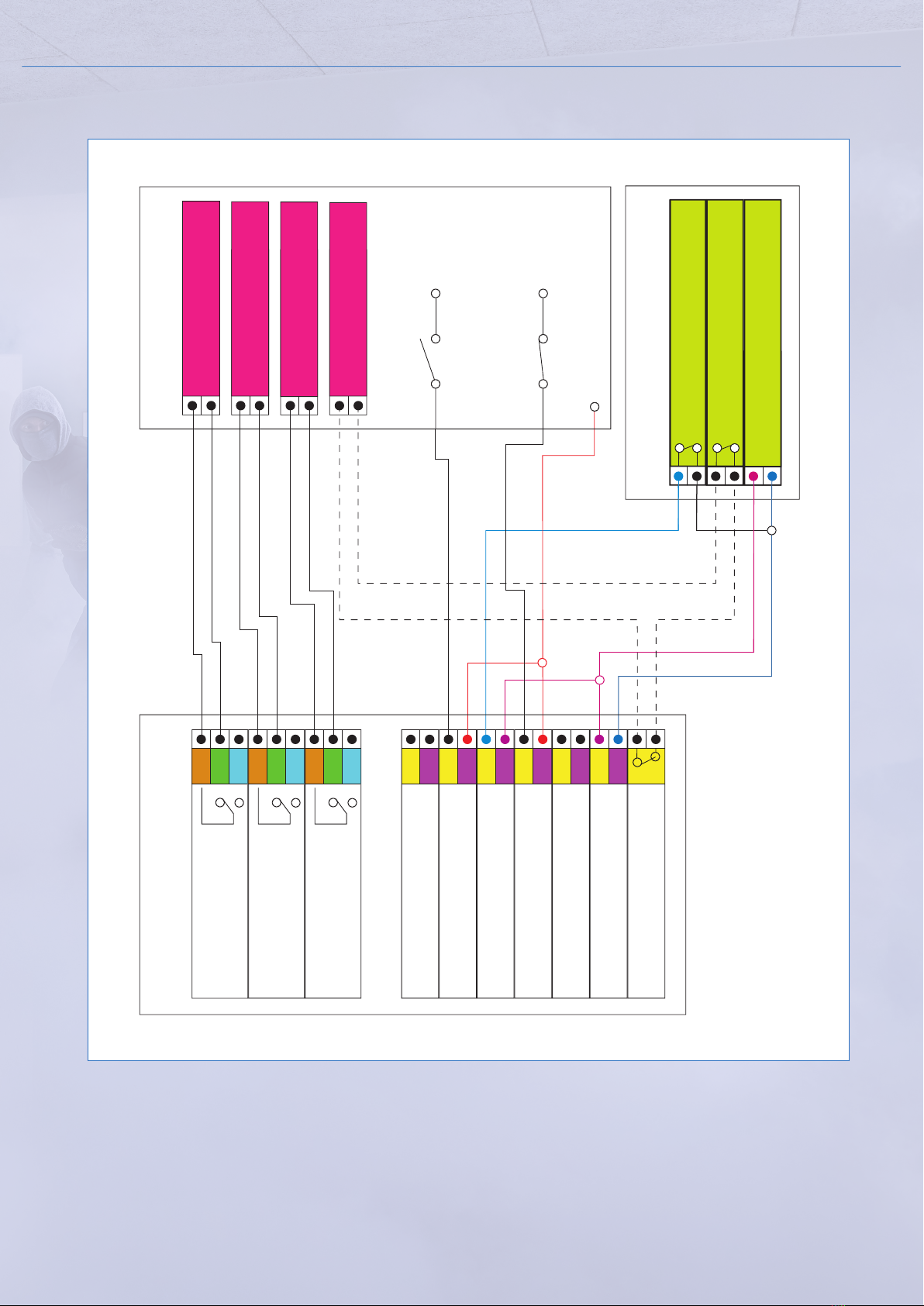
Zone Fog
Zone Fault
Zone Fluid
Zone Tamper
Disable Signal
Alarm Signal
Closed in daytime
Opens with alarm
Tamper
Motion
Connection to alarm panel (typical installation)
INSTALLATION MANUAL

PROTECT 800i C™I 1500i C™
9 I SECURED IN SECONDS
Dipswitch
DIP Function
1
Heat disable
ON = The heating element disconnects
if disable is activated
2Fog time
3 Fog time
4 Fog time
5Arm*
6 Primary*
7 Secondary*
8Fire-alarm delay **
9 Reserved. Leave in OFF position
10 Error indicator. ON = Beeper connected
* ON = normal open
OFF = normal closed
** ON = delay is active
Inputs
Tamper Potential-free switches activate (open) when the covers are removed. They can be used in the alarm
system’s tamper circuit.
12V Built-in 12V supply system that delivers 0.1A – mainly to supply the secondary circuit, e.g.
a PIR sensor.
ARM Can be activated permanently by selecting an active break signal and by not connecting anything to
the terminals.
Primary The primary trigger signal is normally taken from the alarm system and activated from it in case of a
break-in.
Secundary The secondary trigger signal is normally taken from a verifying sensor such as a room sensor or a door
switch.
DIS The disable function can be used to stop the Fog CannonTM when it is producing fog. The signal is con-
nected to the alarm, so the Fog CannonTM is disconnected when the alarm is disconnected.
Fire
Connection of 12 V DC, N/O signal from the re alarm system. In case of a re alarm this signal will
disconnect the Fog CannonTM as long as the signal is active. Also, the
Fog CannonTM will activate a sound signal and report an error on the system error relay.
INSTALLATION MANUAL

PROTECT 800i C™I 1500i C™
10 I SECURED IN SECONDS
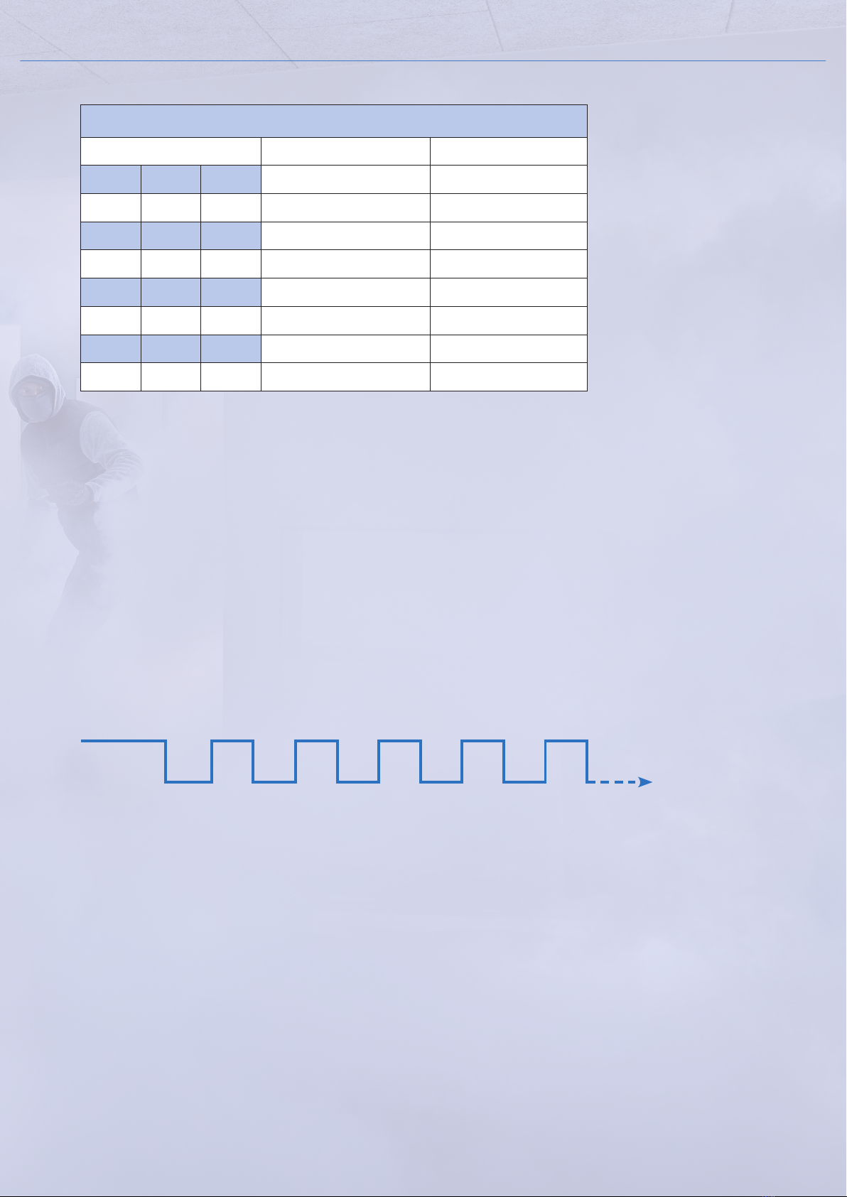
PROTECT 800i C™
Dip settings Fog time Fog volume
Dip 2 Dip 3 Dip 4 m³
OFF OFF OFF demo -
ON OFF OFF 20 sec 350
OFF ON OFF 40 sec 700
ON ON OFF 60 sec 850
OFF OFF ON 60 sec + 1 min. 1000
ON OFF ON 60 sec + 5 min. 1275
OFF ON ON 60 sec + 10 min. 1900
Fog volume
In the tables below the fog volume mentioned is based on the industry standard of security fog. A
change in visibility is gained through longer/shorter time with fog (adjustment of the unit), more/less
Fog Cannons™ and/or different placing of the unit(s). It’s important to perform a test ring of the
installation - and not only rely on the calculation of cubic metres.
Total time in max. pulse mode = 11 min.: 60 sec. + pulse shots.
Total fog production = 1900 m3.
Total capacity in the uid container = 3 complete sequence in pulse mode.
INSTALLATION MANUAL
The reduction in visibility at 1m during the tests carried out during the NF&A2P 2 shield
certication (EN 50131-8: 2019 and RTC 50131-8) of the 800i C™ is 50 sec. for 150 m3and
1136 sec. for maintaining opacity up to 3m.
PROTECT 800i C™I 1500i C™
11 I SECURED IN SECONDS
INSTALLATION MANUAL
Pulse function
Break Break
60/80 sec. fog
Fog output Fog output Fog output
Fog outputFog output
BreakBreakBreak
PROTECT 1500i C™
Dip settings Fog time Fog volume
Dip 2 Dip 3 Dip 4 m³
OFF OFF OFF demo -
ON OFF OFF 20 sec 425
OFF ON OFF 40 sec 850
ON ON OFF 60 sec 1350
OFF OFF ON 80 sec 1600
ON OFF ON 80 sec + 4 min. 1950
OFF ON ON 80 sec + 9 min. 2740
Total time in max. pulse mode = 10 min. and 20 sec.: 80 sec. + pulse shots.
Total fog production = 2740 m3.
Total capacity in the uid container = 2 complete sequence in pulse mode.
The reduction in visibility to 1m during the tests carried out during the NF&A2P 2 shield
certication (EN 50131-8: 2019 and RTC 50131-8) of the 1500i C™ is 36 sec. for 150 m3and
3215 sec. for maintaining opacity up to 3m.
PROTECT 800i C™I 1500i C™
12 I SECURED IN SECONDS
5. Test and hand over
INSTALLATION MANUAL
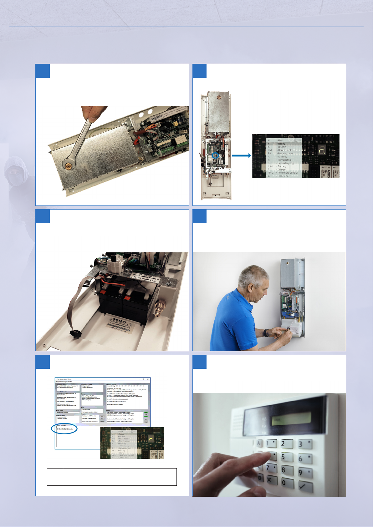
23
20 Loosen the nozzle with a wrench (17) if changing
angle and/or direction of the fog (up to 30°).
Fasten again with the same tool.
21
22
PROTECT 800i CTM
10-15
PROTECT 1500i CTM
15-25
Min.
24 25
Check the control signals before testing.
Remember to heat the system before testing. Full-scale test: Remember that the test must
include the entire alarm installation.
Place and connect the uid container. Also remember
the cable for measuring the uid level.
Connect the battery. First connect wires and then
push the batteries up until they click into place.
One battery measures 97 x 43 x 51 mm.
PROTECT 800i C™I 1500i C™
13 I SECURED IN SECONDS
Service agreement
Finally, a contract of service must be made, which should contain an agreement for min. 1 year of
service incl. test.
A service agreement with the customer includes the following:
• Visually inspect the fog uid level.
Durability: 5 years from production date in unopened packaging. 2 years from date of installation.
Do not use when discolored!
• Check the loading capability and the age of the batteries.
If the batteries are more than 2 years old they must be replaced.
• Check if there is any fault indicated on the Fog Cannon™.
• Check that the nozzle is clean of foreign bodies.
• Check if there are any signs of sabotage and check the sabotage switches.
• Check that the verifying sensor is working correctly.
• Make a full-scale-test, where the interaction between all systems is tested (also the re alarm
system if there).
INSTALLATION MANUAL
27
28 29
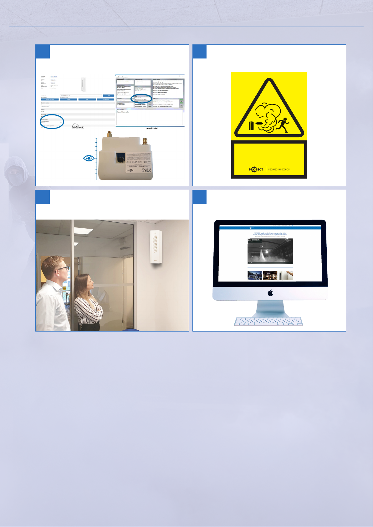
WARNING
SECURITY FOG SYSTEM INSTALLED
PROTECTGLOBAL.COM
26 Check the uid level after testing (hand over the
fog machine with a full uid container).
Remember to put warning labels on the
windows/doors.
Before leaving the installation all users must be
instructed in how the fog machine works.
The users must be informed that further information
can be found on www.protectglobal.com.

PROTECT 800i C™I 1500i C™
14 I SECURED IN SECONDS
6. Error messages and troubleshooting
In case of error, read the error code on the Fog Cannon’s LED display and the error code description below.
We refer to PROTECT IntelliSuite™ V.2.50.0.0, which is a free diagnostic tool used with the PROTECT Intelli-
Connector™ cable or with remote access via integrated PROTECT IPCard™.
Learn more at www.protectglobal.com.
Faultnding
Fluid Output activated when there is enough uid left for one full discharge
Fault Output activated in case of system error. Error type can be read in the display
Fog When the Fog Cannon™ produces fog, this output will activate
External LED status indicator
– a service function in disarm status
One Red ash every 10 sec. (E1) Mains power failure (and no critical failure at the same time)
Three Red ashes every 10 sec (E3) Fire alarm input activated (and no critical failure at the same time)
Four Red ashes every 10 sec (E4) Low battery voltage (and no critical failure at the same time).
Alarm installer is required!
Constant Red ashing Serious failure(s) detected. Alarm installer is required!
Fuses
PROTECT 800i C™PROTECT 1500i C™
F1
(Incoming Power/High Voltage) 10 AT 10 AT
F3 (Heating rod) 6,3 AT 8 AT
F4 (PCB) 0,5 AT 0,5 AT
Error codes
H. H: Heat
r. r: ready
d. d: disable
H.d. Hd: Heat disable
B. . Bt: Blocking timer
A. A: Arm trig
P. P: Primary trig
S. S: Secondary trig
b.A.t. bat: battery
C. C: Charge
E. E: Error + no
1.234567890
1.234568790
rc. rc: Remotely controlled*
norc. norc: No remote control signal
rd. Remotely disabled*
rHd. rHd: Remotely heat disabled*
rP. rP: Remote primary*
rb. rb: Remotely blocked*
rF. rF: Remote re alarm*
rPA rPA: Remote panic alarm activated*
*Only relevant if Intelli products are installed.
INSTALLATION MANUAL

PROTECT 800i C™I 1500i C™
15 I SECURED IN SECONDS
E1: Mains voltage failure - auto-reset.
Check power supply and fuses, transformer connections
E2: Lowuidmessage–auto-reset.
Install new uid container. Note: low uid, does not mean empty, but one full discharge left.
E3: Fire alarm activated – auto-reset.
If there is or has been 12V on FIRE-terminals. Reset re alarm.
E4: Battery voltage too low – auto-reset.
Batteries need a recharge – or changing. Should an E4 show up without batteries installed, the PCB
must be replaced.
E5: Battery charge tried for 24 hours without success.
Change batteries or alternatively try to recharge with an external charger.
E6: Battery failed in load test.
Change batteries.
E7: Temperature on PCB too high.
Check if there is ventilation (fresh air) around the machine.The temperature in the housing might be
too high to cool down the PCB. Max. temperature is 70°C.
E8: Temperature on PCB too low.
Temperature in the room and around the Fog Cannon™ is too low. When the machine is cold and PCB
temperature lower than 5°C it cannot start up. Possible solution is to heat up the room so that the
temperature of the printed circuit board exceeds 5°C.
E9: Temperature on thermal sensor too high (or there is bad connection).
To check the function of the thermal sensor, you must disconnect the sensor, take it out, connect the
2 wires to a voltmeter (must be capable of measuring mV). Try carefully to heat the tip of the sensor
with a lighter or similar. It should be possible to measure a voltage of between 10 and 15 mV.
Also check that the sensor is properly connected to the terminals, or alternatively fasten the wires.
Green to + and white to center terminal. - terminal is not used.
If the E9 continuously shows up: By cold machine; change PCB – By warm machine; change sensor.
Also check that there is no short circuit from sensor wire running to ground.
Sometimes, after several short test launches in a row, the E9 error can appear. The reason for this may
be overheating of the nozzle end. In this case, the machine must cool down before it can re again.
E10: Temperature on thermal sensor too low (after initial heating).
Check thermal overload fuse on the end of heating element.
There is a reset pin in the middle of the thermal fuse.
Check fuse F3 on the PCB.
If heating failure occurs, you can check the resistance in the heating cartridge.
Switch off the main power.
Pull out the 4-pole plug next to the glass fuses.
Use an Ohm meter and measure between the white and the brown wire.
The resistance shall be approx.:
800i C™: 53 Ohm
1500i C™: 41 Ohm
Note that the values can uctuate 2-3 Ohm.
Be sure that there is full passage/connection through the thermal overload fuse.
Check thermal sensor: green to + and white to center terminal. - terminal is not used. Check that the
connection is OK. Test the sensor by taking out the sensor and its wires. Heat up the tip of the sensor
(with a lighter or similar) while a voltmeter is connected. It shall be possible to measure a value of
10-15 mV.
If the machine should be warm, but with an E10 fault telling that it is cold, there may be a loose
connection inside the sensor. Then change the sensor.
There may also be an error on PCB. Then change the PCB.
E12: Pump-timeout.Thepumphasbeenrunningfortoolong.Nouidow,etc.
Fluid container empty - change container.
Fluid container not connected.
If the machine has not produced fog for a long time (1 year or more) the pump can be blocked.
In this case it can help to knock a little on the end of the pump while it is activated.
INSTALLATION MANUAL

PROTECT 800i C™I 1500i C™
16 I SECURED IN SECONDS
E13: The built-in 12 V supply overloaded due to congestion.
Too much extra equipment connected to the 12V supply or there is a short cut in connected
equipment. Remove the overload or repair the short cut.
If you cannot wake up the 12 Volt supply after a reset – change the PCB.
E14: Error in load test circuit.
Check the white ceramic resistance (next to the beeper) – it might have lost or broken its connection
to the PCB. Repair the soldering or change the PCB.
E17:Nouidcontainerdetected.
Install uid container and the wire. Check on the PCB. Change to a new uid container.
Replace the PCB.
E18:Wronguidcontainerdetected.
Replace the uid container with a correct type.
E19: Fluid level too low to run detected.
Replace the uid container.
E22: Fluid container empty.
The uid container has less than one discharge left. Replace the uid container.
ADDITIONAL INFORMATION:
Battery test
The machine will carry out a regular battery test every 24 hours.
Before installing new batteries, you can make your own battery test either with a professional battery
tester – it should show a voltage >12,3V and a capacity >0,8 Ah. Or alternatively use a voltmeter.
Measure the voltage to >12.3V. Connect a 20-21 Watt lamp – this should illuminate bright and clear for a
minimum of 10 seconds and the voltage should at the same time not be lower than 11V.
If lower than 11V the capacity is down to “bad conditioned battery” and you will soon get the message E6
(battery failed in load test).
After the test, the voltage shall increase again to more than 12V.
Well-charged and well-conditioned, the battery will have a voltage of 12,5 to 12,8V.
E4,E5andE6:Wheninstallingnewbatteries
Please be aware that batteries are of lead acid type. This type of battery cannot be stored for more than
3-4 months. When installing a new battery that already has been stored too long you will in many cases
get a new “battery error” shortly after. Check that new batteries are well charged and in good condition.
External LEDs
During normal function, the LEDs are only visible when the DIS input is powered 12V or all fog time
DIP-switches 2, 3, 4 are in off position.
The green light will ash while heating. When the machine is ready there will be a constant green light.
Yellow light means low uid, or the at cable not connected to the uid container.
Red light is error signal.
Read the error code in IntelliCloud™, with IntelliSuite™ or on the display on the PCB.
Beeper
The beeper will sound when an error occurs or when uid is low.
The beep frequency does not refer to a specic error.
The beeper makes sounds 1 time/sec. the rst minute, after which it sounds 1 time/min.
If there is connection to external equipment, the beeper can be disconnected.
Reset
E1 to E4 and E22 have an automatic reset. Other errors must be manually reset after repair/service.
Alternatively, you can always make a manual reset by pressing the reset button for 4 seconds.
INSTALLATION MANUAL

PROTECT 800i C™I 1500i C™
17 I SECURED IN SECONDS
7. Warnings
Spilled fog uid from dripping or other, which has
gathered on the oor underneath the machine, im-
mediately after the system has been activated or in
connection with the handling of the fog uid, must
be removed immediately due to the risk of slipping
and falling.
Do not swallow the fog liquid and keep it away from
children and animals. In case of ingestion of large
quantities: Contact a physician immediately. Avoid
contact with eyes. In case of contact with eyes, rinse
immediately with clean water for min. 15 minutes.
If irritation continues, contact a physician. In case
of direct contact with skin rinse thoroughly with
water and soap.
Avoid prolonged stays in fog lled premises as this
can irritate the mucous membrane in the eyes, nose,
and throat. The effect is temporary and only occurs
in connection with prolonged stays in the dense fog.
Never stick your ngers or other objects behind the
grille in front of the nozzle. The nozzle may be hot
and touching it may cause burns. Do not look direct-
ly into the nozzle.
Flammable or heat-sensitive objects must be placed
at least 35 cm from the nozzle.
The Fog Cannon™ must only be cleaned using a
damp cloth.
Do not spray the Fog Cannon™ with water.
Air the room for 20 minutes within the rst hour of
fog activation to avoid condensation.
The installer must ensure that staff who work in
the secured premises on a daily basis are informed
about the proper rules of precaution when operat-
ing the Fog Cannon™.
If the Fog Cannon™ is installed in premises with pub-
lic access, the staff needs to be instructed in how to
guide visitors and show them the way out in case the
Fog Cannon™ should re unintentionally at a time
where people have access to the secured premises.
The electrical connections of the Fog Cannon™ must
only be handled by certied electrical tter. The
system MUST be connected to earth to meet electri-
cal safety requirements and must only be serviced
by instructed personnel. PROTECT™ and our distrib-
utors worldwide provide training sessions regarding
correct mounting, setting and use of the system.
The system should be tted with max. 16A fuses.
The device must be connected to the mains supply
via a plug or via switch which break all the conduct-
ing poles (both live and neutral) in accordance with
the wiring rules.
The system must be set correctly to prevent over-
dosing.
Never install the system without supervision (con-
nection to alarm panel and control centre).
Service/test the system once a year. Servicing/tests
must be carried out by an alarm technician.
The system must be placed outside normal reach.
The system must not be placed e.g. near the oor
where animals or children can reach it.
The system must not be installed in a way which
blocks emergency exits or re escapes when red.
Place the system with the distance from the nozzle
the nearest object or surface being min. 2.5 m.
Secure the system properly.
Make sure that there is sufcient ventilation space
around the system (minimum 10 cm). Do not t the
system in a closed cavity space.
Disconnect the mains supply before removing pro-
tective covers. Live parts are accessible inside the
device, and there may be risk of electrical chock.
The system is produced for use in a dry indoor
climate (IP20) and must therefore not be placed
outdoors or in damp rooms.
Special precautions must be taken where the fog
machines are installed in locations with automatic
re alarm systems and in blocks of ats.
Before installing the fog machines the installer must
ensure that this can be done in accordance with re-
levant national legislation and regional regulations.
The installer must inform the authorities, the con-
trol centre and security staff of the installation.
Before service on signalling cables, the Fog Cannon™
and connected equipment such as alarms, etc. the
Fog Cannon™ must be protected against uninten-
tional ring.
The system must be protected against activation
when the secured premises are in normal use.
If the above instructions are not observed, PROTECT
A/S shall not be liable for any consequences resul-
ting from such non-observance.
Certain types of thermal paper, thermal labels and
certain types of ink used for print on plastic wrap-
pings and plastic bags can be damaged by the fog.
This PROTECT Fog Cannon®is only to be installed
and used in the country, from where it is purchased.
Local PROTECT™ dealers/installers only service ma-
chines purchased in their own countries.
INSTALLATION MANUAL

PROTECT 800i C™I 1500i C™
18 I SECURED IN SECONDS
8.Consequencesoftheuseofunauthorizeduidin
PROTECT Fog Cannons®
The complete 100% tested and guaranteed performance & no harmful side effects can only be
achievedbyusingapprovedPROTECT™foguid.
9. Warranty terms and exceptions
We generally refer to our general terms of sale and delivery, which are sent together with the order
conrmation.
Cancellation of the warranty: The use of unautho-
rized uid in a PROTECT Fog Cannon®results in the
cancellation of the warranty.
Risk of machine defects: Use of unauthorized uids
can cause damage to heating element, such as rust.
Furthermore, there is a high risk of obstruction of
the nozzle, which will reduce the release of security
fog.
Risk of lack of activation with an alarm signal: If
the pump cannot withstand the chemical composi-
tion of the unauthorized uid, the pump may fail
causing an absence of fog machine activation in a
real-life scenario of alarm activation.
Risk of toxic fumes formation: Unauthorized uid
can become toxic by heating and/or pressure, which
can mean a risk to humans, animals, and food.
Risk of condensation (residue): If the molecular
composition of the uid is not correct, its consistency
does not adjust to the exit diameter of the nozzle
with the consequent risk of condensation and pos-
sible damage to electronics, fabrics, furniture, etc.
Low density risk: Unauthorized uid may have a
too low density, which makes it useless as a security
system by fog.
The warranty does not cover fog uid or batteries
(consumables), nor the wear caused by the normal
use of the fog machine. The transport costs of the
equipment are also excluded from the warranty.
The PROTECT™ security fog uid has an expiration
time of 2 years from the installation of the uid
container in the Fog Cannon™, and 5 years if it has
not been installed and has been stored in its origi-
nal packaging, in a cool, dry place protected from
sunlight. Once the expiration date has passed, a re-
placement is recommended to maintain the proper-
ties and density of the security fog.
The warranty will be void if the product has not
been installed in accordance with the quick guide
provided in the original PROTECT™ packaging and
the manual which can be downloaded electroni-
cally, or if spare parts or fog uid not provided by
PROTECT™ have been used.
The system must be set correctly to prevent over-
dosing.
Never install the system without supervision (con-
nection to alarm panel and control center) and ser-
vice/test the system once a year. Servicing/tests
must be carried out by an alarm technician. Failure
to do so will result in the warranty being void.
PROTECT™ provides a 60-months’ warranty for de-
fects in the products (Xtratus®/Xtratus Flex®: 24
months) calculated from the invoice date on the
customer’s (the installer’s) invoice to its customer,
and not more than 66 months from the product
being delivered by PROTECT™ to the customer, cf.
3.2. in our delivery terms. Complaints must be made
immediately.
PROTECT™ provides a 12-months’ warranty on addi-
tional equipment, spare parts and repair work.
INSTALLATION MANUAL

PROTECT 800i C™I 1500i C™
19 I SECURED IN SECONDS
10. Approvalsandcertications
Models800iC™and1500iC™areNF&A2P2shieldscertiedaccordingtotheNF324-H58standard
Certifying organization: AFNOR (www.marque-nf.com) and CNPP (www.cnpp.com).
Applicable standards: EN 50131-8:2019 & RTC 50131-8.
Certicate numbers: 9024000001A0 & 9024000002A0.
Protection index: IP 20.
Mechanical shock protection index: IK08.
Security Grade 2.
Environmental Class II.
Operating temperature (min/max): 5/80 °C.
INSTALLATION MANUAL

PROTECT 800i C™I 1500i C™
20 I SECURED IN SECONDS
Organisme certificateur
AFNOR Certification
11, rue Francis de Pressensé
93571 LA PLAINE SAINT-DENIS Cedex
: (33) 1.41.62.80.00
Site Internet : http://www.marque-nf.com
Organisme certificateur
CNPP Cert.
Route de La Chapelle Réanville –CS 22265
27950 LA CHAPELLE LONGUEVILLE
:(33) 2.32.53.63.63
Site Internet : http://www.cnpp.com
MATERIELS DE SECURITE ELECTRONIQUES –DETECTION D’INTRUSION
ELECTRONIC SECURITY EQUIPMENT – INTRUSION DETECTION
Ce document comporte 2 pages /This document consists of 2 pages (MCP F 10-13 W–04/2022) Page 1
C
C
CE
E
ER
R
RT
T
TI
I
IF
F
FI
I
IC
C
CA
A
AT
T
T/
/
/C
C
CE
E
ER
R
RT
T
TI
I
IF
F
FI
I
IC
C
CA
A
AT
T
TE
E
E
N
N
N°
°
°9
9
90
0
02
2
24
4
40
0
00
0
00
0
00
0
00
0
01
1
1A
A
A0
0
0
est autorisée à apposer les marques NF et A2P sur le produit selon les conditions définies dans le référentiel de certification
NF324-H58 (rév. 19) /Is allowed to affix NF and A2P certification marks on the following product, according to the NF324-H58 (rev 19) certification
standard:
Marque commerciale /Trade Mark ::
PROTECT
Référence commerciale /Model :
PROTECT 800i C
Type de produit /Product type :
Dispositifs générateurs de brouillard / Security fog devices
Gamme /Product line :
Non Applicable / Not Applicable
Ce certificat atteste /This certificate attests that :
-que les produits désignés sont conformes aux normes listées en page(s) suivante(s) et aux spécifications complémentaires qui
leurs sont applicables, tel que spécifié dans le référentiel de certification NF 324 –H 58,
designated products are in compliance with standards listed following page(s) and complementary applicable specifications as described in the
NF324-H58 certification standard,
-que le système qualité de la société a été évalué conformément au référentiel de certification NF 324 –H 58
the quality system has been assessed according to the NF324-H58 certification standard
Caractéristiques certifiées essentielles / Main certified characteristics
Niveau de sécurité
Sécurity level :Type d’alimentation principale
Prime power source type :
230 V
RTC
Liaison
Links :
Filaire
Wire Loops
Sécurité contre la fraude
Tamper security :
Ouverture
Opening
Classe d’environnement
Environmental class :
II
Réduction visibilité / maintien
Reduced visibility / continuation :
Oui
Yes
La liste des composants associés à ce produit figure en annexe à ce certificat. The component list for the above-mentioned product can be
found in the appendix.
Ce certificat n’est valable qu’accompagné de son annexe et sous réserve des résultats des contrôles effectués par AFNOR
Certification et CNPP cert qui peuvent prendre toute sanction conformément aux règles générales de la marque NF, au référentiel
général H0 de la marque A2P et au référentiel de certification NF 324 –H 58.This certificate is only valid with the attached appendix hereafter
and subject to control results performed by AFNOR Certification and CNPP Cert. who can take the appropriate sanction accordingto the general rules
of NF mark, the H0 standard-special regulations for A2P mark and the NF324-H58 certification standard.
Ce certificat est valable jusqu’au 03/08/2025.This certificate is valid until 2025/08/03.
Il annule et remplace tout certificat antérieur.This certificate cancels and replaces any previous certificate.
Date de prise d’effet, le 04/08/2022 Date de prise d’effet, le 04/08/2022
Julien NIZRI Christophe BODIN
Directeur Général d’AFNOR Certification Directeur CNPP Cert.
General Managerof AFNOR Certification Manager of CNPP Cert.
PROTECT A/S
HASSELAGER CENTERVEJ 5, st.
DK-8260 VILBY J
DANEMARK
Lieu(x) de fabrication / For its factory located in:000210P2
AFNOR CERTIFICATION ET CNPP Cert.
MEMBRES DE L’EFSG
INSTALLATION MANUAL
This manual suits for next models
1
Table of contents
Other Protect Fog Machine manuals


