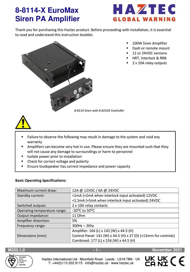
Haztec EuroSmart 8-82613-X User manual

Haztec International Ltd ∙ Moorfield Road ∙ Leeds ∙ LS19 7BN ∙ UK
T: +44(0)113 202 9115 ∙ info@haztec.uk ∙ www.haztec.uk
8-82613-X (V3)
EuroSmart Class D
Siren Amplifier
M373.1.1 - 1 - October 2022
Thank you for purchasing this Haztec product. Before proceeding with installation, it is essential to read
and understand this instruction manual.
Basic operating specifications:
Supply Voltage Range:
10-30VDC
Maximum Current Draw:
22A @ 12V / 11A @ 24V
Standby current
0.1A in standby / 0.016A during sleep1
Amplifier Output Range:
10-200W
Recommended Fuse Rating:
30A @ 12V / 15A @ 24V
Dimensions:
125mm x 132mm x 43mm
1 When in sleep mode the siren is drawing a small amount of current. Therefore, it is recommended that
an isolator switch is fitted to prevent battery drain when the vehicle is not in use for long periods of time
▪Available as siren only or with optional
2 or 8 programmable switched outputs
▪Battery voltage monitor
▪Adjustable power output
▪Variable volume
▪Over temperature shutdown
▪Non-destructive short circuit protection
▪Non-destructive reverse polarity protection
▪RRB channel

Haztec International Ltd ∙ Moorfield Road ∙ Leeds ∙ LS19 7BN ∙ UK
T: +44(0)113 202 9115 ∙ info@haztec.uk ∙ www.haztec.uk
8-82613-X (V3)
EuroSmart Class D
Siren Amplifier
M373.1.1 - 2 - October 2022
Safety requirements for installation:
▪This product must be installed by persons competent in vehicle electrical installations
▪Regularly inspect the product to confirm correct operation
▪Failure to observe the following may result in damage to the system and void the warranty
▪Amplifiers can become very hot in use; ensure they are mounted such so as not to cause damage
to personnel or surroundings
▪Ensure power is isolated before attempting installation
▪Ensure correct voltage and polarity of all electrical connections
▪DO NOT allow water or any other liquids to come into contact with this unit or its wiring
▪Care must be taken to ensure that water ingress cannot occur through mounting or wiring holes
▪Ensure that the vehicle is stationary and in a safe location before attempting setup of the siren
▪Siren sound levels can permanently damage hearing. Always wear ear protection when testing
▪Ensure that all connections are well made and protected from corrosion
Limited Warranty:
▪Haztec International Ltd. warrants this unit to be free from defective material and workmanship
and agree to repair or replace if proven defective through normal use and occurs within two years
of the purchase date
▪The warranty is considered void if the unit has been tampered with, improperly serviced, subjected
to abuse or misuse, or improperly installed in a vehicle
▪The warranty does not cover accidental damage

Haztec International Ltd ∙ Moorfield Road ∙ Leeds ∙ LS19 7BN ∙ UK
T: +44(0)113 202 9115 ∙ info@haztec.uk ∙ www.haztec.uk
8-82613-X (V3)
EuroSmart Class D
Siren Amplifier
M373.1.1 - 3 - October 2022
Contents:
Page Content
1,2 Introduction; Warnings; Warranty
3 Contents
4 Setup and Installation
5, 6 Appendix 1….... Siren Amplifier Front Panel
7 Appendix 2….... Status LED and Set-Up/Reset Button
8 Appendix 3….... Main Wiring Harnesses
9 Appendix 4…... 2-way Switched-Output Connector
10 Appendix 5…... 8-way Switched-Output Connector
11 Appendix 6…... Speaker Installation
12,13 Appendix 7…... Power & Impedance selection
13 Appendix 8…... Impedance & Power Selection Tables
14 Appendix 9…... Self-Diagnosis Event Codes
14 Appendix 10…. Wiring Instructions
15,16 Appendix 11…. Specifications
17 Appendix 12…. Drawings & Schematics
18-20 Appendix 13….Installation
21 Appendix 14…. CANbus Networking

Haztec International Ltd ∙ Moorfield Road ∙ Leeds ∙ LS19 7BN ∙ UK
T: +44(0)113 202 9115 ∙ info@haztec.uk ∙ www.haztec.uk
8-82613-X (V3)
EuroSmart Class D
Siren Amplifier
M373.1.1 - 4 - October 2022
Set-Up & Installation:
1. Get to know the product:
▪Before proceeding it is important to familiarise yourself with the product by referring to
Appendices 1 & 2 of this instruction manual
2. Temporary Power Supply:
▪Where possible, use a suitable temporary power supply to assist in the set-up procedure.
Refer to Appendix 3 for connectivity
3. Speaker Output selection:
▪Determine speaker set-up requirements –refer to Appendix 6
▪Follow the instructions in Appendices 7 & 8 to check and alter the output settings
4. Installation:
▪Decide upon a suitable and secure location for the unit (see Appendix 13)
▪The location must:
➢be dry
➢be a firm and flat surface (ideally metal)
➢be away from any local sources of heat and warm air
➢not restrict the unit’s ventilation (see Appendix 13)
➢allow access to the reset button and status LED
5. Power Supply Harness:
▪Before installing the power supply harness into the vehicle, it is important to consider the
following:
➢Always use the harness supplied with the unit. Once the cable routing is determined
the wires can be cut to the required length
➢If the supplied harness is not a suitable length ,they can be replaced with cables of
equal gauge and specification
➢When routing cables through bulkheads, rubber grommets should be used to prevent
the wires from becoming damaged or cut
➢The power should always be taken from the vehicle’s battery via a waterproof fuse
mounted as close to the battery terminal as possible. Note that any cable between
the fuse and the battery will not be protected
➢DO NOT insert the fuse until the installation is complete
➢Refer to the tables in Appendix 11 for fuse ratings

Haztec International Ltd ∙ Moorfield Road ∙ Leeds ∙ LS19 7BN ∙ UK
T: +44(0)113 202 9115 ∙ info@haztec.uk ∙ www.haztec.uk
8-82613-X (V3)
EuroSmart Class D
Siren Amplifier
M373.1.1 - 5 - October 2022
Appendix 1 | Siren Amplifier Front Panel
▪Without switched output board –see over page for key
▪With optional 2-way switched output board –see over page for key
▪With optional 8-way switched output board –see over page for key

Haztec International Ltd ∙ Moorfield Road ∙ Leeds ∙ LS19 7BN ∙ UK
T: +44(0)113 202 9115 ∙ info@haztec.uk ∙ www.haztec.uk
8-82613-X (V3)
EuroSmart Class D
Siren Amplifier
M373.1.1 - 6 - October 2022
Key to Front Panel
1. MASTER INPUT: Used for controlling siren by handset/control panel or microphone. Provides a
power feed for the control panel
2. SLAVE OUTPUT 1: Acts as an extension to provide CAN or LIN bus control to other equipment
such as Lightbar controller, flasher etc. Does not provide a power feed
3. SLAVE OUTPUT 2: Acts as an extension and is normally occupied by external EuroSmart switcher
(if used). Does not provide a power feed
4. I/O CONNECTOR: For connection to vehicle horn, position lamps, interlock, data logger, radio,
and programmable inputs
5. POWER INPUT & SPEAKER OUTPUT: Provides power, ground, and speaker connections - See
Appendix 3 & 8
6. USB PROGRAMMING SOCKET: Allows the siren to be set up using the EuroSmart USB
programming software
7. 2 & 8-WAY SWITCHED OUTPUTS: If fitted, allows the user to control external equipment via the
programmable switched outputs. Each output is rated up to 10A (max. 32A total for 8-way
boards) - See Appendices 4 & 5
8. PROGRAMMABLE INPUTS: Positive or negative switched inputs, any of which can be assigned to
control any output. Also, able to sense signals related to vehicle operating conditions, i.e., parking
brake, ignition switch or position lamps - See Appendix 3
9. POWER FOR SWITCHED OUTPUTS: Requires two positive feeds rated at 16A each and one
negative return - See Appendix 5
10. COOLING AIR VENTS: The amplifier uses forced air cooling. The cooling fan draws air in from the
rear of the unit and exhausts through the front –See Appendix 13
IMPORTANT Do not block the air intake or cooling vents. The fan will switch on automatically when the
temperature of the heatsink rises above 50OC. It will then vary its speed automatically as the temperature
changes. A minimum void of 50mm around the siren must be kept clear to allow for heat dissipation and
even air flow

Haztec International Ltd ∙ Moorfield Road ∙ Leeds ∙ LS19 7BN ∙ UK
T: +44(0)113 202 9115 ∙ info@haztec.uk ∙ www.haztec.uk
8-82613-X (V3)
EuroSmart Class D
Siren Amplifier
M373.1.1 - 7 - October 2022
Appendix 2 | Status LED and Set-Up/Reset Button
1. STATUS LED
▪Lights for 1 second on initial power up
▪Indicates the siren status –See Appendices 8 & 9
▪Indicates if a fault or event has been logged
▪To provide protection the unit will not output any power to the speaker when a fault is
indicated –See Appendix 9
▪When a fault is corrected the indicator will go off and normal operating mode is resumed
▪In the case of an overheat the event log will clear itself without user interaction once the
temperature falls back within normal operating parameters
2. SET-UP / RESET BUTTON
▪If a fault is detected press & hold the button for 3 seconds to clear the event log
▪If the log cannot be cleared, please refer to Appendix 9 for the event code
in order to carry out relevant investigations to diagnose and rectify the fault
▪Please note that the Reset/Setup button is also used to read and configure the
impedance and power settings

Haztec International Ltd ∙ Moorfield Road ∙ Leeds ∙ LS19 7BN ∙ UK
T: +44(0)113 202 9115 ∙ info@haztec.uk ∙ www.haztec.uk
8-82613-X (V3)
EuroSmart Class D
Siren Amplifier
M373.1.1 - 8 - October 2022
Appendix 3 |Main Wiring Harnesses
T6a: Speaker & Power Connector
Terminal
No.
Wire Colour
Function
1
Red
Positive [+] feed via fuse
2
3
Black
Permanent negative [-ve] ground
4
5
Brown/White
Speaker [-]
6
Brown
Speaker [+]
T12a: Input & Control Connector
Terminal
No.
Wire Colour
Function
1
White
HRT Input
2
Pink
Interlock Input
3
Orange
Side-Light Input
4
Red/Black
Data Logger Output
5
Light Blue
Tone Input 1
6
Yellow
Tone Input 2
7
Green
Tone Input 3
8
Violet
Tone Input 4
9
Blue
Radio Re-broadcast Input 2 [+]
10
Blue/White
Radio Re-broadcast Input 2 [-]
11
Red
Radio Re-broadcast Input 1 [+]
12
Red/White
Radio Re-broadcast Input 1 [-]

Haztec International Ltd ∙ Moorfield Road ∙ Leeds ∙ LS19 7BN ∙ UK
T: +44(0)113 202 9115 ∙ info@haztec.uk ∙ www.haztec.uk
8-82613-X (V3)
EuroSmart Class D
Siren Amplifier
M373.1.1 - 9 - October 2022
Appendix 4 | 2-way Switched Output Connector
▪Maximum current 10A per output
▪Main feed is via appropriately fused and rated customer supplied wiring
▪Switching of outputs is pre-programmed on delivery of the amplifier
▪Can also be used to switch negative but the current flow must conform as shown in Fig.2
T4a: 2-way Switched Output Connector [+ve switching]
Terminal
No.
Wire
Colour
Function
1
User
supplied
wiring
Switched Output 2 [+]
2
Switched Output 1 [+]
3
Positive [+] feed via fuse
4
Positive [+] feed via fuse
T4a: 2-way Switched Output Connector [-ve switching]
Terminal
No.
Wire
Colour
Function
1
User
supplied
wiring
Negative [-] feed via fuse
2
Negative [-] feed via fuse
3
Switched Output 1
4
Switched Output 2
(Fig.1 +ve switching)
(Fig.2 -ve switching)

Haztec International Ltd ∙ Moorfield Road ∙ Leeds ∙ LS19 7BN ∙ UK
T: +44(0)113 202 9115 ∙ info@haztec.uk ∙ www.haztec.uk
8-82613-X (V3)
EuroSmart Class D
Siren Amplifier
M373.1.1 - 10 - October 2022
Appendix 5 |8-way Switched Output Connector
▪Maximum current 10A per output
▪Maximum total current 32A
▪Main feed is via appropriately fused and rated customer supplied wiring to pins 2 & 3 of the input
feed connector
▪Earth return is via appropriately rated customer supplied wiring to pin 1 of the input feed
connector. (Note: This ground terminal is for the operation of the switcher board and is additional
to the main siren ground connection)
▪Switching of outputs is pre-programmed on delivery of the amplifier
T3a: 3-way Input Feed Connector
Terminal
No.
Wire
Colour
Function
1
User
supplied
wiring
Negative/Ground [-]
2
Positive [+] feed via fuse
3
Positive [+] feed via fuse
T8a: 8-way Switched Output Connector
Terminal
No.
Wire
Colour
Function
1
User
supplied
wiring
User programmed
2
3
4
5
6
7
8
T4b: 4-way Control Input Connector
Terminal
No.
Wire
Colour
Function
1
Blue
User programmed
2
Yellow
3
Green
4
Violet

Haztec International Ltd ∙ Moorfield Road ∙ Leeds ∙ LS19 7BN ∙ UK
T: +44(0)113 202 9115 ∙ info@haztec.uk ∙ www.haztec.uk
8-82613-X (V3)
EuroSmart Class D
Siren Amplifier
M373.1.1 - 11 - October 2022
Appendix 6 |Speaker Installation
▪When two or more speakers are wired in series it is important to connect positive (+ve) of one
speaker to the negative (-ve) of the next
▪When connecting multiple speakers, they must have the same power rating and impedance
▪See below diagrams for speaker wiring configurations
Calculating Speaker Impedance
▪Z= Impedance of a single speaker
▪ZT = Total Impedance
▪N= Number of speakers
▪Where an application requires two or more speakers ensure that the correct impedance is
calculated using the below formula and selected on the amplifier. (Note: Speakers must be of
identical power and impedance)
➢For two or more speakers connected in parallel:
ZT= Z / N
➢For two or more speakers connected in series:
ZT = Z x N

Haztec International Ltd ∙ Moorfield Road ∙ Leeds ∙ LS19 7BN ∙ UK
T: +44(0)113 202 9115 ∙ info@haztec.uk ∙ www.haztec.uk
8-82613-X (V3)
EuroSmart Class D
Siren Amplifier
M373.1.1 - 12 - October 2022
Appendix 7 |Power & Impedance Selection
CAUTION! It is essential to fully read and understand these instructions before making any changes to the
amplifier settings
Verifying the Impedance & Power Settings:
▪Press and hold the ‘setup’ button until the LED illuminates
▪Release the button and after 1 second the LED will go out
▪After a pause of 3 seconds the LED will begin to indicate the settings
➢Refer to the table in Appendix 8 to verify the amplifier settings
➢The first series of ‘short’ flashes indicate the impedance setting
➢After a short pause, the second series of ‘long’ flashes indicates the power setting
➢The settings sequence will continue to repeat until cancelled
➢Press and hold the ‘setup’ button once to exit the verification process
Adjusting the Impedance & Power Settings:
▪Press and hold the ‘setup’ button until the LED illuminates
▪Release the button and after 1 second the LED will go out
▪The unit is now ready to have the impedance set (Note: The process must be started within 3
seconds of releasing the ‘setup’ button, otherwise the unit will commence settings verification)
▪Use the ‘setup’ button to select the required speaker impedance
➢Refer to the table in Appendix 8 to verify the amplifier settings
➢Each press of the button will advance the previously saved setting by 1 increment
➢The LED will flash once to confirm each press
▪Press and hold the ‘setup’ button until the LED illuminates
▪Release the button and after 1 second the LED will go out
▪The unit is now ready to have the power set (Note: The process must be started within 3 seconds
of releasing the ‘setup’ button, otherwise the unit will commence settings verification)
▪If the power setting does not require adjusting, press and hold the ‘setup’ button until the LED
gives multiple short flashes to confirm the process is complete
➢Each press of the button will advance the previously saved setting by 1 increment
➢The LED will flash once to confirm each press
▪Press and hold the ‘setup’ button until the LED gives multiple short flashes to confirm the process
is complete
▪Repeat the verification process to confirm that the changes have been saved

Haztec International Ltd ∙ Moorfield Road ∙ Leeds ∙ LS19 7BN ∙ UK
T: +44(0)113 202 9115 ∙ info@haztec.uk ∙ www.haztec.uk
8-82613-X (V3)
EuroSmart Class D
Siren Amplifier
M373.1.1 - 13 - October 2022
Cancelling the Setup Process:
▪Disconnect power to the amplifier for 10 seconds
▪Re-connect the power and the amplifier will return to normal operating mode
▪The settings will not have been saved unless confirmed by the LED
Appendix 8 |Impedance & Power Selection Tables
Impedance Selection Table
No. of button presses
(short LED flash)
Total speaker impedance
(Ohms)
Supported power range of speakers (Watts)
1
4
10 - 150
2
5.5
10 - 200
3
8
10 - 200
4
11
10 –200*
5
16
10 –150
* Default setting 100W 11 Ohm
Power Selection Table
No. of button presses
(long LED flash)
Speaker power
(Watts)
1
10
2
20
3
30
4
40
5
50
6
60
7
70
8
80
9
90
10
100*
11
110
12
120
13
130
14
140
15
150
16
160
17
170
18
180
19
190
20
200
* Default setting

Haztec International Ltd ∙ Moorfield Road ∙ Leeds ∙ LS19 7BN ∙ UK
T: +44(0)113 202 9115 ∙ info@haztec.uk ∙ www.haztec.uk
8-82613-X (V3)
EuroSmart Class D
Siren Amplifier
M373.1.1 - 14 - October 2022
Appendix 9 |Self-Diagnosis Event Codes
LED Signal
Event Code
1 sec on + 2 sec off
Amplifier overheating1
1 long + 2 short flashes
Low battery voltage or faulty amplifier
3 flashes
Low battery voltage. 12V operation but voltage below 9V
6 flashes
High battery voltage. 24V operation but voltage above 32V
8 flashes
Fault on temperature sensor
1 Heatsink temperature has reached 100OC. Event log remains until temperature falls back to 70OC
Note: If it is not possible to clear the event log, please contact the supplier for further assistance
Appendix 10 |Wiring Instructions
Speaker Wiring:
▪For cable runs less than 2m between amplifier and speaker use 18AWG (1.0mm2)cable
▪For cable runs greater than 2m between amplifier and speaker, and for volume critical
installations, 15AWG (1.5mm2)cable is required
▪When two or more speakers are wired in parallel, use a separate pair of wires (rated as above)
directly from the amplifier to each speaker
Amplifier Wiring:
▪The power supply and ground/earth cables must be capable of carrying a current in excess of 30A
for 12V installations, and in excess of 15A for 24V installations. Wire thickness will depend on the
length of the cable run in each specific installation. The type and quality of wire used must also be
considered
▪The maximum cable thickness that can be fitted into the 6-pin connector is 12AWG (2.0mm2).
Two positive and two negative terminals are provided so that the current can be shared across
two wires
▪Where excessive runs are required, it may be necessary to run a single wire of sufficient thickness
close to the amplifier, and then divide the feed into two 12AWG (2.0mm2) wires
Other Wiring:
▪All other wiring to and from the amplifier and switched outputs must be selected giving the same
considerations as for the main feed cables
▪Where the siren is installed more than 2m from the vehicle battery the ground wire should be
connected to the nearest chassis point
▪Positive feeds over 2m must be extended using an adequate AWG size cable to prevent a voltage
drop exceeding 1V

Haztec International Ltd ∙ Moorfield Road ∙ Leeds ∙ LS19 7BN ∙ UK
T: +44(0)113 202 9115 ∙ info@haztec.uk ∙ www.haztec.uk
8-82613-X (V3)
EuroSmart Class D
Siren Amplifier
M373.1.1 - 15 - October 2022
Appendix 11 |Specifications
General
Supply voltage range:
10-30VDC
Maximum current draw:
22A @ 12V / 11A @ 24V
Recommended fuse rating:
30A @ 12V / 15A @ 24V
Amplifier output range:
10-200W
Inputs & Outputs
Number of programmable control inputs:
4 [only when 8-way output board is fitted]
Horn input:
+ve switched1
Interlock input:
>7VDC to wake from sleep mode
<2VDC to enter sleep mode
Radio re-broadcast input:
2 channels
Position lamp inputs:
6-40VDC
Data logger output:
Short-circuit protected 100mA
Max. output voltage equal to battery voltage
1 Can be –ve switched via EuroSmart configuration utility
Connectors
Modular connectors:
1 x ‘6p6c’ Master input for connection to
handset/control
1 x ‘6p6c’ Slave 1
1 x ‘6p6c’ Slave 2
Slaves acting as extensions to connect to other
equipment
6-way 15A connector:
Power; earth and speaker
(see Appendix 10 for wiring instructions)
12-way low current connector:
All ancillary inputs including 2 x RRB

Haztec International Ltd ∙ Moorfield Road ∙ Leeds ∙ LS19 7BN ∙ UK
T: +44(0)113 202 9115 ∙ info@haztec.uk ∙ www.haztec.uk
8-82613-X (V3)
EuroSmart Class D
Siren Amplifier
M373.1.1 - 16 - October 2022
Features
Battery voltage monitoring:
Power control, safety shutdown and control panel
functions shutdown
Variable volume:
From 0 –100% level
>78% efficiency throughout range
Adjustable power output level: can be used with
any speaker from 4 –16 Ohm impedance:
From 0 –100% level
>78% efficiency throughout range
Maximum power output:
150W / 4 Ohm speaker
200W / 5.5 Ohm speaker
150W / 16 Ohm speaker
Max. 60V applied to the speaker
Over-temperature shutdown:
Triggered when PCB temperature reaches 100OC
Non-destructive short-circuit protection:
Active when speaker output shorted or
overloaded
Non-destructive reverse polarity protection:
Active for power input
Standby current:
0.1A in standby / 0.016A during sleep
RRB channel:
Electronic volume control
Optional Extras
2-way board:
2 x 10A programmable outputs
+ve or –ve switched
8-way board:
8 x 10A programmable outputs
+ve switched only
Max. total output 32A
Basic Dimensions (mm)
Overall width (including mounting wings):
132
Length (without electrical connectors):
125
Height:
43
Minimum void around siren:
50mm1
1 Required to accommodate electrical connectors, wiring harnesses and maintain air flow around the
siren to assist with heat dissipation –see Appendix 13

Haztec International Ltd ∙ Moorfield Road ∙ Leeds ∙ LS19 7BN ∙ UK
T: +44(0)113 202 9115 ∙ info@haztec.uk ∙ www.haztec.uk
8-82613-X (V3)
EuroSmart Class D
Siren Amplifier
M373.1.1 - 17 - October 2022
Appendix 12 |Basic Dimensions

Haztec International Ltd ∙ Moorfield Road ∙ Leeds ∙ LS19 7BN ∙ UK
T: +44(0)113 202 9115 ∙ info@haztec.uk ∙ www.haztec.uk
8-82613-X (V3)
EuroSmart Class D
Siren Amplifier
M373.1.1 - 18 - October 2022
Appendix 13 |Installation
The siren must be installed in a dry location and on a flat and even (ideally metal) surface. Ensure the
siren is kept away from any sources of heat and warm air and that airflow is not restricted (see Direction
of Airflow and Airflow Void). It is also important to allow access to the reset button and status LED
If the siren is to be installed vertically the cooling fan must be positioned uppermost
COOLING
FAN
RESET BUTTON &
STATUS LED

Haztec International Ltd ∙ Moorfield Road ∙ Leeds ∙ LS19 7BN ∙ UK
T: +44(0)113 202 9115 ∙ info@haztec.uk ∙ www.haztec.uk
8-82613-X (V3)
EuroSmart Class D
Siren Amplifier
M373.1.1 - 19 - October 2022
Direction of Airflow:
Airflow Void:
A minimum of 50mm must be left clear around the siren to ensure even airflow. DO NOT allow the
cooling fan or inlet vents to become blocked or obstructed

Haztec International Ltd ∙ Moorfield Road ∙ Leeds ∙ LS19 7BN ∙ UK
T: +44(0)113 202 9115 ∙ info@haztec.uk ∙ www.haztec.uk
8-82613-X (V3)
EuroSmart Class D
Siren Amplifier
M373.1.1 - 20 - October 2022
Wiring Looms:
When installing the siren, the wiring looms must be adequately secured in place using the cable ties
provided. The distance (mm) from the connector body to the cable tie must be observed as shown in the
images below
Looms should be smoothly formed and not at immediate right angles from the connector body as this will
put strain on the terminals and also risk disconnection from the siren
Table of contents
Other Haztec Amplifier manuals
