HB Products HBSR User manual

Instruction manual - HBSR – Refrigeration Switch (HBSR-003-UK) 1 / 12
WE INCREASE
UPTIME AND EFFICIENCY
IN THE REFRIGERATION INDUSTRY
Instruction manual
HBSR – NH3,HFC & Brine switch
For the detection of refrigerants and/or phase separation
between oil and ammonia

Instruction manual - HBSR – Refrigeration Switch (HBSR-003-UK) 2 / 12
WE INCREASE
UPTIME AND EFFICIENCY
IN THE REFRIGERATION INDUSTRY
Table of contents
Safety Instructions...........................................................................3
Introduction..................................................................................... 4
Measurement principle ................................................................... 4
Design .............................................................................................. 4
Technical data.................................................................................. 5
Function...........................................................................................5
Examples of usage ...........................................................................6
Installation instructions................................................................... 6
Accessories ......................................................................................7
Power connection............................................................................7
Installation guide ............................................................................. 8
LED indication..................................................................................9
Fault detection ................................................................................9
Further information.......................................................................11
Declaration of conformity .............................................................12

Instruction manual - HBSR – Refrigeration Switch (HBSR-003-UK) 3 / 12
WE INCREASE
UPTIME AND EFFICIENCY
IN THE REFRIGERATION INDUSTRY
Safety Instructions
CAUTION! Read the instruction manual before commencing work! Heed all warnings to the letter!
Installation of HBSR requires technical knowledge of both refrigeration and electronics. Only qualified
personnel should work with the product. The technician must be aware of the consequences of an
improperly installed sensor, and must be committed to adhering to the applicable local legislation.
If changes are made to type-approved products, this type approval becomes void. The product's input and
output as well as its accessories may only be connected as shown in this guide. HB Products assumes no
responsibility for damages resulting from not adhering to the above.
Explanation of the symbol for safety instructions. In this guide, the symbol below is used to point out
important safety instructions for the user. It will always be found in places in the chapters where the
information is relevant. The safety instructions and particularly the warnings must always be read and
adhered to.
CAUTION! Refers to a possible limitation of functionality or risk of use.
NOTE! Contains important information about the product and provides further tips.
The person responsible for operation must commit to adhering to all the legislative
requirements, preventing accidents, and doing everything to avoid damage to people and
materials.
Intended use, conditions of use The HBSR switch is manufactured so as to detect various refrigerant types,
as well as to detect phase separation between oil and ammonia. If HBSR is to be used in a different way or
for another purpose, and if the operation of the product in this function is determined to be problematic,
prior approval must be obtained from HB Products.
Prevention of collateral damage Make sure that qualified personnel assess any faults and take necessary
precautions before attempting to make replacements or reparations, so as to avoid collateral damage.
Disposal instructions: HBSR is built so that the modules can easily be removed and sorted for disposal.

Instruction manual - HBSR – Refrigeration Switch (HBSR-003-UK) 4 / 12
WE INCREASE
UPTIME AND EFFICIENCY
IN THE REFRIGERATION INDUSTRY
Introduction
HBSR is a level switch for detection of liquid
refrigerants, including NH3 , HFC and brine.
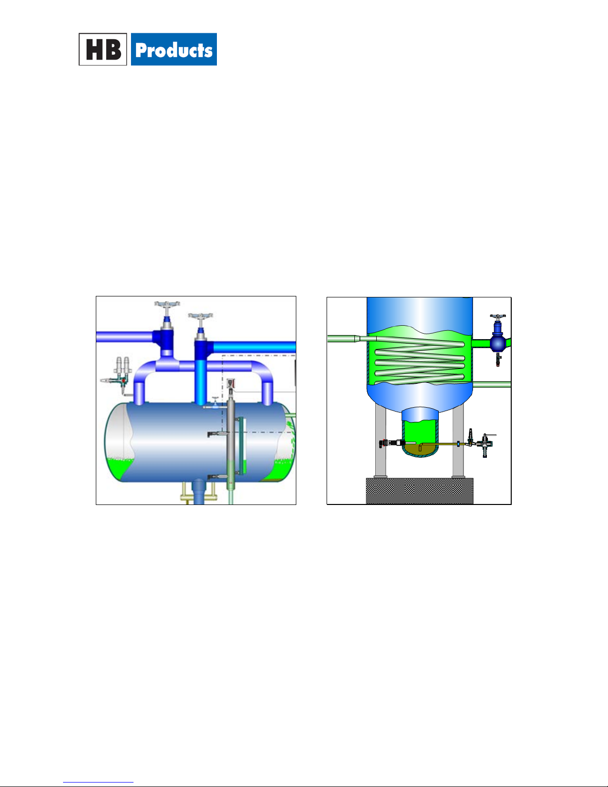
Typically it is installed in/on the reciever, pump
separators, economisers, heat exchangers, or as
an oil-accumulation-alarm in ammonia systems.
The sensor's measurement principle makes it
unique for these purposes, since the properties
of the measurement principle enable it, among
other things, to detect phase separation between
oil and ammonia.
The sensor is also built to resist high pressure and
low temperatures.
HBSR is not suited for use on CO2systems. Here
the HBSC2 switch type must be used.
Measurement principle
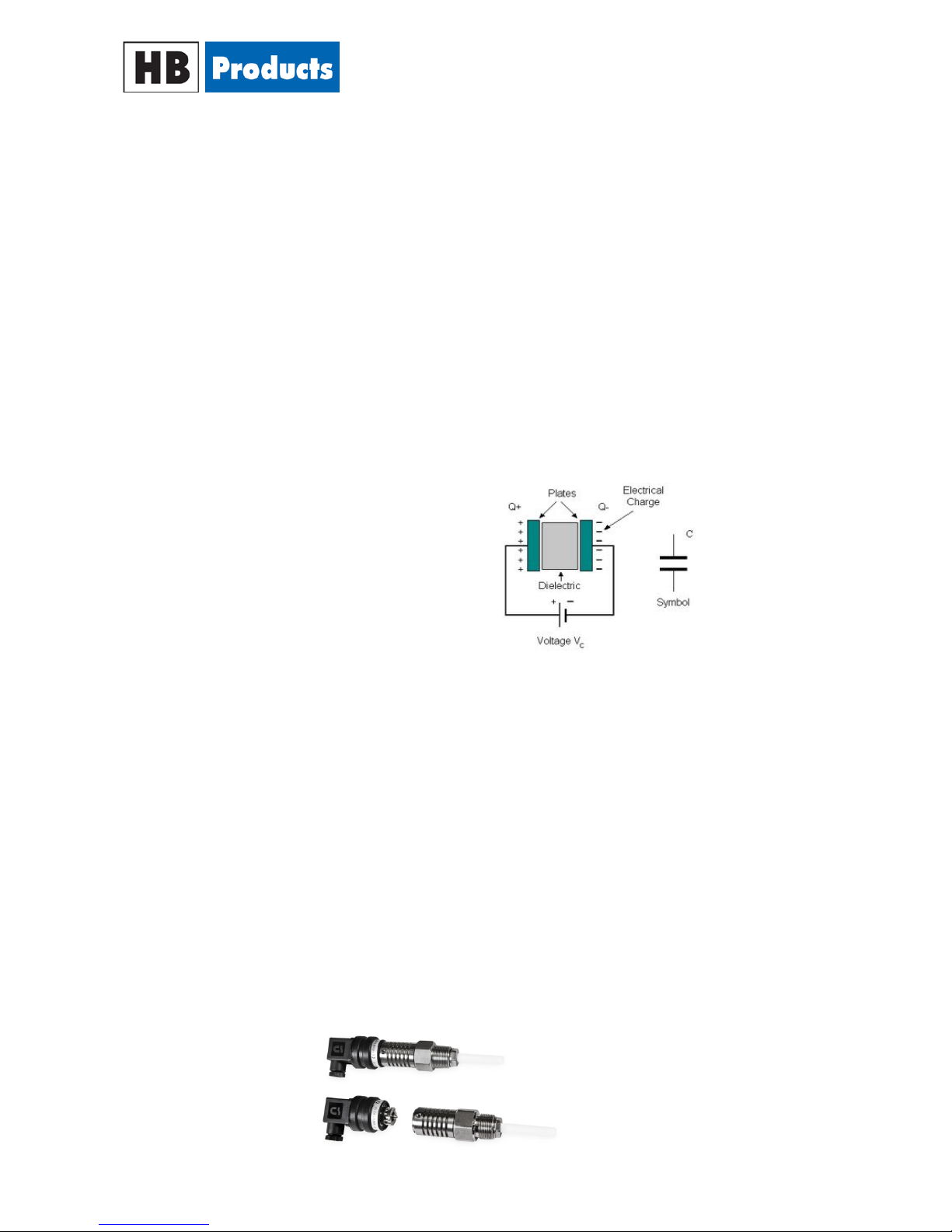
The sensor is a capacitive sensor. The capacitive measurement principle is based on the electrical
properties in the proximity of a capacitor. A capacitor is an electrical component that is capable of building
and sustaining an electrical charge.
Principally, a capacitor consists of two plates.
When a charge is applied to a plate, the other
plate will be charged with the opposite polarity
and retain the charge until it has been grounded.
The magnitude of the charge (the capacitance)
that can be generated depends, among other
things, on what is found between the plates.
The substance between the plates is referred to
as a dielectric.
Rather than two plates, the sensor for level
measurement is shaped as a cylindrical rod.
When liquid covers the sensor, the measured
capacity changes.
The conductivity of a material can vary depending
on temperature, chemical composition, and the
homogeneity of the material, and therefore it can
in some cases require a different factory
calibration.
HB Products sensors are calibrated so that they differentiate between conductive and non-conductive
liquids.
In refrigeration systems, the oil, HFCs and liquid CO2are not regarded as conductive fluids, whereas
refrigerants such as ammonia, and brine are regarded as conductive.
Design
The sensor consists of a mechanical part and an electronic part. These are easily separated by loosening 2
grub screws, or for mechanisms with mounting tabs, by pressing the electronic part in towards the
mechanical part and turning the housing counter-clockwise until a wave washer presses it out of the
mounted position. The electronic part is designed in accordance with IP65 waterproof rating and so as to
withstand vibrations. The mechanical part is produced in AISI304/PTFE and tested to withstand high
pressure.

Instruction manual - HBSR – Refrigeration Switch (HBSR-003-UK) 5 / 12
WE INCREASE
UPTIME AND EFFICIENCY
IN THE REFRIGERATION INDUSTRY
Technical data
Connection:
Supply: 24 V DC ±10%
Current draw: Max 50 mA
Plug: DIN 43 650
Required cable size: 3 x 0,34 mm2
Required cable glands: PG7 / M8
Output:
Transistor output: PNP or NPN
Output function: NC or NO
Installation conditions:
Ambient temperature: -20…+50°C
Refrigerant temperature: -50*…+100°C
Max. operational pressure: 100 bar
Waterproof rating: IP65
Vibrations: IEC 68-2-6 (4g)
Authorisations – EMC Test:
EMC Emission EN61000-3-2
EMC Immunity EN61000-4-2
* For installation with heating element.
Otherwise, the minimum temperature is – 30°C.
Mechanical specifications:
Thread connection: ¾”
Materials, mechanical: AISI304/PTFE
Materials, electronic: Nylon 6 (PA)
Weight: 500 g
Indication:
LED indication : 4 x LED (red)
Accessories:
Heating element: HBHE
Plug with power supply: HBPA
(90/240 VAC for 24 VDC)
Function
HBSR is a level switch for detecting common refrigerants, including NH3and brine, but it can also be used
for oil return management in ammonia refrigeration systems.
Typically it is installed in/on the receivers, pump separators, economisers, heat exchangers, or as an oil-
accumulation-sensor on ammonia systems.
The sensor differentiates between refrigerant, gas, and oil, so that the electrical signal from the sensor
changes when the liquid level drops below/rises above the level that it was installed at.
The sensor is calibrated to switch in the centre of the sensor's cylindrical part, with a hysteresis of about 1
mm.
When the refrigerant is on the same level or above this point, 4 LEDs light up (irrespective of the output
relay NO/NC).
All terminals are protected against improper termination with a supply voltage up to 40 V. If
the supply voltage is greater than 40 V the electronics will be damaged

Instruction manual - HBSR – Refrigeration Switch (HBSR-003-UK) 6 / 12
WE INCREASE
UPTIME AND EFFICIENCY
IN THE REFRIGERATION INDUSTRY
Examples of usage
The HBSR switch is well suited to be used for
-Indication of high and low refrigerant levels in liquid separators, pump separators, economisers,
and inter coolers.
-on/off control of liquid injection in liquid separators, pump separators, economisers, and inter
mediate coolers
On ammonia refrigeration systems, it can also be used for
-Indication of accumulated oil in oil sumps, oil pots, liquid separators, economisers, inter mediate
coolers. It is used here with a reversed contact function for automatic oil discharge/drainage.
Installation instructions
The following applies during installation:
1) Where the sensor is installed in a threaded sleeve/pipe stub, this should be welded at a 5-10°
upwards angle relative to the horizontal, so as to prevent the formation of liquid pockets.
2) The installation length of the sensor must be taken into account, since there must be at least
2mm between the sensor's mechanical part and other fixed or moving parts.

Instruction manual - HBSR – Refrigeration Switch (HBSR-003-UK) 7 / 12
WE INCREASE
UPTIME AND EFFICIENCY
IN THE REFRIGERATION INDUSTRY
Accessories
The sensor can be installed with a heating element (HBHE) so as to prevent icing of the sensor at low liquid
temperatures. Using a power supply (HBPA), the switch can be connected to 90/240VAC
HBPA is installed instead of the plug which was
provided. The power supply is universal and can be
connected to 90/240 V AC.
HBHE is installed on the cylindrical part under the
plug. The female socket is installed on the sensor
and heating element supply, and the sensor is
connected to the heating element and distributed.
HBHE has a 24 V DC supply and therefore cannot be
used together with HBPA.
Power connection
HBSR can be delivered with a PNP or NPN output.
The connection depends on the selected sensor type as well as the type of controller/PLC used.
CAUTION! In case of welding work on the unit, the electronic part must be removed.
Welding work can damage the electronics. The mechanical part of the sensor must not be
installed in the pipe socket during welding.

Instruction manual - HBSR – Refrigeration Switch (HBSR-003-UK) 8 / 12
WE INCREASE
UPTIME AND EFFICIENCY
IN THE REFRIGERATION INDUSTRY
Installation guide
HBSR is installed on a pipe socket depending on the type of thread on the sensor. Sensors with NPT"/BSPT"
are sealed with Teflon tape or liquid gasket. For other thread types, solid gasket is used.
To install the HBSR sensor, a 2.5 mm Allen key, shifting
spanner, and gasket must be used.
Loosen the two set screws.
Separate the electronic part from the mechanical part.
Apply liquid gasket on sensors with a conical thread, and
solid gasket to sensors with a cylindrical thread.

Instruction manual - HBSR – Refrigeration Switch (HBSR-003-UK) 9 / 12
WE INCREASE
UPTIME AND EFFICIENCY
IN THE REFRIGERATION INDUSTRY
Install the mechanical part in the container or overflow
pipe and tighten to a tightening torque dependant on the
thread type (80-150 Nm)
Install the electronic part again and fix with 2 set screws.
LED indication
4 x red LEDs indicate the liquid level
Irrespective of the output function NO/NC, LEDs are activated
at liquid level.
Fault detection
NOTE! Fault detection on the electronic function can be carried out without releasing pressure
from the system or disassembling the mechanical part from the sensor.

Instruction manual - HBSR – Refrigeration Switch (HBSR-003-UK) 10 / 12
WE INCREASE
UPTIME AND EFFICIENCY
IN THE REFRIGERATION INDUSTRY
The easiest way to carry out fault detection is to have an extra mechanical part available.
The electronic part to be tested is installed on the extra mechanical part.
The electronics are tested using a piece of steel thread or non-isolated electrical cable and a glass of water
(see the illustration).
If the electronics switch the way they are supposed to during the test, one can exclude the possibility of a
fault on the sensor.
In case of faults, it is enough to only replace the electronic part.
Fault
Possible Reason
Correction of Fault
No LED is on when the sensor is
in the medium.
No supply to the sensor or
defective cable/plug.
Check the power supply or
replace the power supply cable.
No output (4 x red LEDs are on
but the output signal is not
active)
Check if the sensor's output
matches the control's input; if it
is a PNP/NPN and NO or NC
respectively.
See the output charge
instructions below.
Create alignment between the
sensor and control so that the
two are identical.
No contact activation
(4 x red LEDs are not on, even
though liquid should activate
the sensor)
There may be dirt between the
electronic housing and the
mechanical housing.
Separate the two parts and clean
the spring tip. Remember to apply
silicone grease on the spring tip
so as to avoid problems with
moisture.
Note! LED is always activated when approx. half of the sensors are covered or immersed in
refrigerant, irrespective of the sensor's output function NC/NO.

Instruction manual - HBSR – Refrigeration Switch (HBSR-003-UK) 11 / 12
WE INCREASE
UPTIME AND EFFICIENCY
IN THE REFRIGERATION INDUSTRY
Delay in sensor activation
1) Can be caused by a gas pocket
that displaces the liquid.
2) The sensor is sealed with (too
much) Teflon tape so that there
is no metallic contact between
the sensor mechanism and the
vessel.
1) Install the sensor so that the
gas pockets cannot displace the
liquid
2) Make sure that the sensor has
a metallic connection to the
container.
Output and 4xLED are
constantly activated, even
though liquid is not in contact
with the sensor.
Threaded sleeves are installed
with a negative slope so that
liquid can collect in the threaded
sleeves, which activates the
sensor.
Place the threaded sleeves
according to the instructions. See
installation.
Function of charge output on pin 3 & 4:
NC: There should be no signal when it is in refrigerant.
NO: There should be a signal when it is in refrigerant.
Sensor repair
The sensor electronics are completely sealed and can therefore not be repaired.
In case of faults with the sensor, it will typically only be necessary to replace the electronics.
Complaint cases are handled by the HB Products dealers/distributors.
Their complaints procedures must be followed before returning the sensor.
Further information
For further information, please visit our website, www.hbproducts.dk, or send an email
to: support@hbproducts.dk.

Instruction manual - HBSR – Refrigeration Switch (HBSR-003-UK) 12 / 12
WE INCREASE
UPTIME AND EFFICIENCY
IN THE REFRIGERATION INDUSTRY
Declaration of conformity
We, HB Products A/S
Confirm with full responsibility that the product:
Category: Instrumentation.
Type: Level switch type HBSR.
Description: Level sensor based on the capacitive measurement principle.
Manufactured: Developed and manufactured by HB Products A/S.
This declaration confirms that the product adheres to the standards outlined below:
EN 61000-6-2: 2005 EMC General Immunity Requirements
Industrial Environment
EN 61000-6-4: 2007 EMC General Emission Requirements
Industrial Environment
According to the European directive:
EMC directive 2004/108/EC
Hasselager, 1 May 2012
Michael Elstrøm
Managing & Technical Director
HB Products A/S – Bøgekildevej 21 – DK8361 Hasselager – support@hbproducts.dk – www.hbproducts.dk
Other manuals for HBSR
1
Table of contents
Other HB Products Switch manuals

HB Products
HB Products HBSC2 User manual

HB Products
HB Products HBSC2 User manual

HB Products
HB Products HBSC2-SSR User manual

HB Products
HB Products HBOR User manual

HB Products
HB Products HBSC2 User manual

HB Products
HB Products HBOC User manual

HB Products
HB Products HBSC2-SSR User manual

HB Products
HB Products HBOC/C User manual