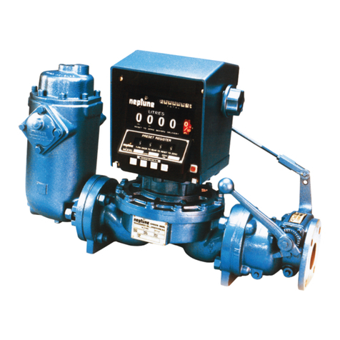
Red Seal Measurement neptune S Operating instructions

Operating and Maintenance Manual
for Type S Flowmeters
M-105
Rev. B
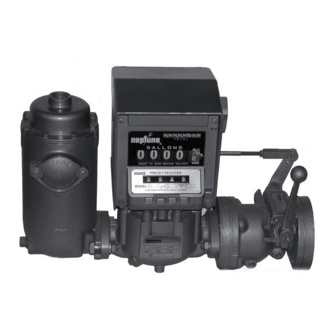
Type S Flowmeters
1" with 800 Series Register
Sold & Serviced By:
Don Johns, Inc.
701 N. Raddant Rd.
Batavia, IL 60510
(630) 454-4700 www.donjohns.com

TABLE OF CONTENTS
Installation ........................................................................................................ 1
Operation.......................................................................................................... 2
Calibration ........................................................................................................ 3
Register Maintenance....................................................................................... 3
1” Type S Flowmeter Auto Stop Valve Adjustment ........................................... 5
Measuring Chamber......................................................................................... 7
General Maintenance ....................................................................................... 8
Troubleshooting Guide ..................................................................................... 9

Page 1
INSTALLATION
For correct installation of flowmeters, Red Seal Measurement is always available for
your assistance. Do not hesitate to call the nearest authorized distributor.
Plan the installation in such a way as to allow the strainer to be coupled directly to the inlet of
cleaned out.
Be careful to allow room for easy removal of the strainer basket.
removal of the greatest possible amount of air from the liquid before metering.
Use pipe cement or tape on male threads only.
anti-drain valve is recommended.
Experience has shown the need for a valve bypass connection to be installed around the
removed for repair.
line should be connected to a drip collecting tank or returned to liquid supply tank.
these directions were followed.
Inlet and outlet are clearly marked; do not install backwards.
on a platform support. Provide space for the removal of valve bonnet and internal parts on
Register.”
equipment is used.
INSTALLATION
Before Installing The Flowmeter
Piping
Air Vent Line
When Installing
After Installing

Page 2
OPERATION
insert ticket.
operating knob to the front stop and remove ticket.
The cumulative totalizer is visible through the mask at the upper right-hand corner of the
register.
Press the setting buttons inward until the desired quantity is noted on the Preset wheels.
Pushing the red emergency stop button will trip the valve. After it has been used either
To insert a ticket be sure that the operating knob is turned to its forward stop. Then depress
on the instruction plate. Turn the operating knob to its rear stop. This resets the visible wheels
Figure 1
Figure 2
Preset 800 Series Printer Register Print Unit Adjustments
It is now impossible to remove the ticket without tearing it.
The Printer Registers are shipped from the factory with the ticket guides properly adjusted. If
1. Remove top cover.
2. Insert a ticket into the printer. Loosen the clamp screws on the rear of the ticket guides.
Move the guides to the right or left as required. Tighten clamp screws. The ticket must slide
freely between the guides.
3. Replace the top cover and reseal.
OPERATION
Cleaning the Strainer
To Operate the Flowmeter
Totalizer
To Set the Preset Mechanism
Emergency Stop
To Insert and Remove the Tickets
To Adjust Ticket Guides
CLAMP
PRESET
BUTTONS
TRIP
ADJUSTING
EMERGENCY
STOP
BUTTON
DUST BAR OPERATING
KNOB
STOP PINS
CLAMP
LETTER

Page 3
CALIBRATION
to properly drain these liquids from volumetric type test measures.
Erratic registration is an indication of trouble in the system and is usually caused by air or dirt
directed.
or by a damaged or worn internal mechanism.
Consistent over-registration or under-registration indicates need for recalibration. See Form TSG-
Red SEal Measurement
REGISTER MAINTENANCE
that the register be returned to the nearest distributor for repair. If a replacement register is
gears in the register.
Figure 3
Change Gear Arrangement
800 SERIES REGISTER
Loosen the two clamp screws on lower front of the register. Lift the register off. On auto-Stop
(Remove cotter pin and washer at valve
end.)
change gears (Figure 3). They must be the same as the gears on the old register and on the
same respective spindles.The number of teeth is stamped on each gear. To remove these
is the same on the new register as on the old one. Each hole is lettered for convenience.
NOTE: Type S meters supplied since 1990 do not utilize the gear shifter mechanism.
CALIBRATION
Flowmeters Reading In Pounds
REGISTER MAINTENANCE
800 SERIES REGISTER
To Remove Register From
Flowmeter

Register masks are made of plastic and require special treatment. Instructions for cleaning
in cleaning glass windshields must not be used as cleaners.
Scouring cleanser and similar material must not be used in cleaning the mask since they
contain abrasives that scratch the surface.
brighten the surface of the mask is never recommended since these substances soften the
surface of the plastic.
View Looking at Back of Register
Figure 4
Left-Hand Assembly Right-Hand Assembly
TO ROTATE REGISTER
assembly from valve.
screws (not shown)
valve operating cam. Reassemble valve operating shaft and install valve operating cam
in the reverse direction. Reinstall two cam retaining screws and shaft seal plug. Reinstall
housing assembly with valve operating cam acting on pilot rod. Secure with four hex
assembly.
To Clean Register Mask
To Rotate the Register

Page 5
1” TYPE S FLOWMETER AUTO STOP VALVE
ADJUSTMENT
Note:
mechanism of the register is in proper position.
To Adjust Valve Linkage With Valve At Outlet of Flowmeter
viewed from rear of register.)
x=x).
5. Depress the emergency stop button and allow the valve to close. At this point the linkage
rechecked.
8. It is sometimes necessary to change the position of the handle. This can be done by loos-
the handle may be positioned away from the register. Fine adjustments may be made by
may also be varied by positioning the end of the rod in the upper or lower holes in the valve
handle.
View Looking at Back of Register
Figure 5
Left-Hand Assembly Right-Hand Assembly
1” Type S Flowmeter Auto Stop
Valve Adjustment

MEASURING CHAMBER
To Remove and Disassemble
To Reassemble Chamber in the
Flowmeter
MEASURING CHAMBER
erratic registration.
Figure 6 Figure 7
Meter Assembled Meter Disassembled
2. Remove the register.
be necessary to tap maincase to free it - insert maincase bolts in holes and hit head of bolt
while pulling upward on chamber. Remove thrust roller bearing plate.
5. Remove the upper half of the chamber. Be careful not to scratch or nick nay part of the
chamber.
7. The chamber is now completely disassembled. The parts may be most easily cleaned of
such as emery cloth or sandpaper.
2. Check that the thrust roller rotates freely in the disc position.
the diaphragm in the chamber half. The disc piston cannot be dropped into the chamber
vertically but must be assembled at a right angle.
upper half. The upper and lower halves should then snap together.
or either part may become damaged. Never use a hammer to insert.
the fault lies within the chamber and it must be disassembled to check for foreign matter or
burrs.
7. Clean out the casing.
8. Lift the chamber by the piston spindle and lower it into position in the main casing. The top

Page 7
so.
that it will not come down on the piston spindle.
the spindle. These nuts are carefully packed and the hole machine-reamed to the size of the
spindle at the factory. Do not try to repack because hand-packed nuts cause excessive friction
and scoring of the spindle.
1. Remove the register and register adapter.
the same reduction. Note: Pack gear train and housing full with
non-water soluble grease on enclosed type.
arm of the gear train so that it will not come down on the piston
spindle.
GENERAL MAINTENANCE
The liquid passing through the measuring chamber must be free of grit and other forms of
sediment in order to prevent unnecessary friction and the scoring of the piston and chamber.
as possible.
as well as the liquid being measured. Over-registration is the result. The Air-Release valve is
intended to prevent this condition by venting this air before it passes through the measuring
chamber.
liquids.
Stufng Box
Leakage at the Stufng Box
Loose or Worn Stufng Box Nut
To Replace the Gear Train
General Maintenance
Sediment
Air
Testing
Storage
Figure 8
Stufng Box

Page 8
TROUBLESHOOTING GUIDE
1. Register Not Working when Liquid is Flowing
Frozen condensation inside register.
Register in need of repair.
2. Leakage at the Stufng Box
3. Chronic Leakage at the Main Case Gasket
Broken gasket or loose bolts.
Excessive line or shock pressure.
4. Reduction in the Rate or Complete Stoppage of Discharge
Blocked strainer due to sediment or frost.
Partially open valve in system.
Pump bypass stuck open.
Air release valve fails to close allowing liquid and pressure to dissipate
back to supply.
5. Over-Registration-Erratic
Air Release Valve jamming on air vent plugged allowing air to pass
Air pockets in closed-end piping in the suction line.
too small or suction lift too great.
6. Under Registration-Erratic
Dirt in the measuring chamber.
Badly worn measuring chamber.
Main casing distorted or damaged.
Damaged internal parts.
7. Consistent Over- or Under-Registration
Flowmeter in need of calibration.
8. Liquid Leaking Out the Air Release Vent
9. Valve Will Not Latch Open
TROUBLESHOOTING
Preset Models

Page 9

Specify Genuine Neptune Replacement Parts
OUT
Sold & Serviced By:
Don Johns, Inc.
701 N. Raddant Rd.
Batavia, IL 60510
(630) 454-4700 www.donjohns.com
Table of contents
Other Red Seal Measurement Measuring Instrument manuals