HB-THERM THERMO-5 HB-100Z1 User manual
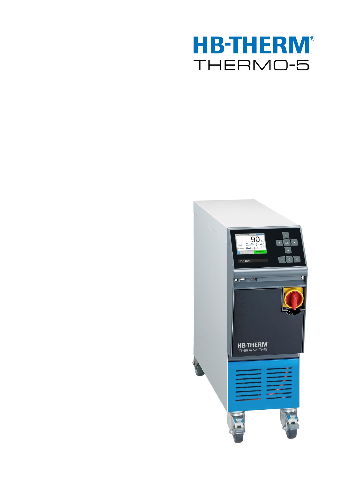
Instruction Manual
HB-100/140/160Z1
Temperature Control Unit

2 O8285-EN 2017-12
HB-THERM AG
Spinnereistrasse 10 (WU 3)
Postfach
9006 St. Gallen
Switzerland
www.hb-therm.ch
Phone +41 71 243 6-530
Fax +41 71 243 6-418
Translation of original instruction
Contents
2017-12
O8285-EN
Instruction Manual
HB-100/140/160Z1
Temperature C ontrolU nit
(Typenschild)

HB-100/140/160Z1 Temperature Control Unit
Contents
O8285-EN 2017-12 3
Index................................................................................................7
1General....................................................................................9
1.1 Information about this manual.....................................9
1.2 Explanation of symbols .............................................10
1.3 Limitation of liability ...................................................11
1.4 Copyright...................................................................11
1.5 Warranty terms..........................................................12
1.6 Customer Service......................................................12
2Safety.....................................................................................13
2.1 Intended Use.............................................................13
2.2 Customer’s responsibility ..........................................14
2.3 Personnel requirements ............................................15
2.3.1 Qualifications..............................................15
2.3.2 Unauthorized persons................................16
2.4 Personal protective equipment..................................17
2.5 Specific dangers........................................................18
2.6 Safety devices...........................................................20
2.7 Stickers and decals ...................................................21
2.8 CE Declaration of Conformity for Machinery.............22
3Technical data ......................................................................23
3.1 General Information...................................................23
3.2 Emissions..................................................................24
3.3 Operating conditions .................................................24
3.4 Connection values.....................................................25
3.5 Operating fluids .........................................................26
3.6 Nameplate.................................................................27
4Structure and function.........................................................28
4.1 Overview....................................................................28
4.2 Brief description.........................................................28
4.3 Functional principle ...................................................29
4.4 Heat transfer medium................................................29
4.5 Connections...............................................................30
4.6 Additional equipment.................................................31
4.7 Operation modes.......................................................32
4.7.1 Main operating modes ...............................32
4.7.2 Auxiliary modes..........................................32
4.8 Work and danger zones ............................................33
5Transport, packing and storage .........................................34
5.1 Safety notes for transport..........................................34
5.2 Transport...................................................................34
5.3 Transport inspection..................................................36
5.4 Packing......................................................................36
5.5 Symbols on the packing ............................................37

HB-100/140/160Z1 Temperature Control Unit
Contents
4 O8285-EN 2017-12
5.6 Storage......................................................................38
6Installation and initial commissioning...............................39
6.1 Safety ........................................................................39
6.2 Requirements for the installation location .................40
6.3 Installation work.........................................................41
6.3.1 Lock castors...............................................41
6.3.2 Water treatment .........................................41
6.3.3 Set the separate connection for system
water..........................................................42
6.3.4 Setting up system connections..................43
6.3.5 Connect data interfaces.............................45
6.3.6 Connect external sensor............................47
7Control...................................................................................48
7.1 Keyboard...................................................................48
7.1.1 Key functions on an individual unit ............48
7.1.2 Key functions and operation on an
individual unit.............................................49
7.1.3 Key functions on unit operated as module.50
7.1.4 Basic display..............................................51
7.2 Operating structure....................................................53
7.3 Menu structure...........................................................54
8Operation ..............................................................................63
8.1 Mains ON...................................................................63
8.2 Registering new modular units..................................64
8.3 Special features for operation of modular units.........65
8.4 Operate singular unit as modular unit .......................66
8.5 Switching on..............................................................67
8.5.1 Normal operation .......................................67
8.5.2 Leak stopper ..............................................68
8.5.3 External sensor..........................................69
8.5.4 Mode 2nd nominal value............................71
8.5.5 Remote mode.............................................72
8.6 Switching off..............................................................75
8.6.1 Cooling down and switching off .................76
8.6.2 Mould evacuation.......................................77
8.6.3 Mould evacuation with compressed air......78
8.7 Emergency stop.........................................................79
8.8 Define access rights..................................................80
8.8.1 Set user profile...........................................80
8.8.2 Set operating release.................................80
8.8.3 Change access code .................................81
8.9 Settings......................................................................82
8.9.1 Setting time zone, date and time ...............82
8.9.2 Define internal measuring points ...............83
8.9.3 Set switch clock .........................................84
8.9.4 Set ramp programme.................................85

HB-100/140/160Z1 Temperature Control Unit
Contents
O8285-EN 2017-12 5
8.9.5 Cyclical change-out of the system water ...87
8.10 Process monitoring....................................................88
8.10.1 Limit value monitoring................................88
8.10.2 Monitor pump wear ....................................90
8.10.3 Optimise controller.....................................91
8.11 Explorer window........................................................92
8.12 Save/Load .................................................................93
8.12.1 Tool data....................................................95
8.12.2 Recording actual data................................97
9Maintenance..........................................................................99
9.1 Safety ........................................................................99
9.2 Open the unit...........................................................100
9.3 Maintenance schedule ............................................102
9.4 Maintenance tasks ..................................................104
9.4.1 Cleaning...................................................104
9.4.2 Pump........................................................105
9.4.3 Temperature measurement .....................106
9.4.4 Pressure measurement............................107
9.4.5 Safety valve..............................................108
9.4.6 Software update.......................................109
9.4.7 Gain access to components.....................111
10 Faults...................................................................................113
10.1 Safety ......................................................................113
10.2 Fault indications.......................................................115
10.2.1 Fault indication display.............................115
10.3 Determine the cause of a fault ................................116
10.4 Troubleshooting chart..............................................116
10.5 Startup after eliminating fault...................................118
11 Disposal ..............................................................................119
11.1 Safety ......................................................................119
11.2 Disposal of materials...............................................119
12 Spare parts..........................................................................120
12.1 Ordering spare parts ...............................................120
13 Technical information........................................................121
13.1 Electrical circuit diagram .........................................121
13.2 Hydraulic scheme....................................................123
13.3 Item location............................................................125
13.4 Legend.....................................................................128
14 Interface cables..................................................................130
14.1 External sensor........................................................130
14.2 External control........................................................131
14.3 Serial data interfaces...............................................131
14.4 CAN-Bus interfaces.................................................133
14.5 Interface HB.............................................................134

HB-100/140/160Z1 Temperature Control Unit
Contents
6 O8285-EN 2017-12
Appendix
A Special execution
B Spare parts list

HB-100/140/160Z1 Temperature Control Unit
Index
O8285-EN 2017-12 7
Index
A
Access code .......................................................81
Access rights ......................................................80
Additional equipment..........................................31
B
Basic display.......................................................51
C
CE Declaration of Conformity.............................22
Cleaning............................................................104
Code ...................................................................81
Connect external sensor.....................................47
Connect interfaces..............................................45
Connection
Cooling water,.................................................25
Electrical .........................................................30
Electrical .........................................................25
main and return line........................................25
separate system water....................................25
Connection values ..............................................25
Control ................................................................48
Controller optimisation........................................91
Cooling................................................................76
Customer Service ...............................................12
Cyclical change-out of the system water............87
D
Danger zones .....................................................33
dangers...............................................................18
Date, set .............................................................82
Disposal............................................................119
Disposal of materials ........................................119
Drain connection.................................................25
E
Electric current....................................................18
Electrical circuit diagram...................................121
Emissions ...........................................................24
F
Faults................................................................113
cause.............................................................116
indications.....................................................115
overview....................................................... 116
Functional principle............................................ 29
H
Heat transfer medium ........................................ 29
Hydraulic connections........................................ 30
Hydraulic scheme ............................................ 123
Hydraulic specialist............................................ 15
I
Installation.......................................................... 41
Installation location ............................................ 40
Intended Use...................................................... 13
Interface cables................................................ 130
Item location..................................................... 125
K
Keyboard............................................................ 48
L
Leak stopper...................................................... 68
Legend............................................................. 128
Liability............................................................... 11
Lock castors....................................................... 41
Logbook Alarms............................................... 116
M
Main switch ........................................................ 20
Maintenance ...................................................... 99
schedule....................................................... 102
tasks............................................................. 104
Maximum fusing............................................... 121
Measurement
flow rate.......................................................... 23
pressure ......................................................... 23
Temperature................................................... 23
Measuring points................................................ 83
Menu structure................................................... 54
Monitoring .......................................................... 88
level................................................................ 89
limit values ..................................................... 88
Pump wear..................................................... 90
Mould evacuation............................................... 77
compressed air............................................... 78

HB-100/140/160Z1 Temperature Control Unit
Index
8 O8285-EN 2017-12
N
Nameplate ..........................................................27
Nominal value 2..................................................71
Normal operation................................................67
O
Opening the unit ...............................................100
Operating conditions...........................................24
Operating fluids...................................................26
Operating release ...............................................80
Operating structure.............................................53
Operation............................................................63
Operation modes................................................32
Overview.............................................................28
P
Packing...............................................................36
Personnel..............................................15, 99, 113
Pressure measurement ....................................107
Professional electrician.......................................15
Protective equipment............................17, 99, 113
Pump.................................................................105
Q
Qualified personnel.............................................15
R
Ramp programme...............................................85
Recording actual data.........................................97
Remote mode .....................................................72
S
Safety..................................................................13
Safety devices ....................................................20
Safety valve ......................................................108
Save/Load...........................................................93
Settings...............................................................82
Software update................................................109
Sound pressure level......................................... 24
Spare parts ...................................................... 120
Special Design..................................................... 9
Status display..................................................... 52
Stickers .............................................................. 21
Storage .............................................................. 38
Structure ............................................................ 28
Surfaces, hot...................................................... 19
Switch clock ....................................................... 84
Switching off....................................................... 75
Switching on....................................................... 67
Symbol display................................................... 52
Symbols
in this manual................................................. 10
Packing .......................................................... 37
rear of unit...................................................... 30
T
Technical data.................................................... 23
Technical information....................................... 121
Temperature measurement ............................. 106
Time, set ............................................................ 82
Tool data............................................................ 95
Transport............................................................ 34
Troubleshooting
Chart ............................................................ 116
U
Used for ............................................................. 13
User profile......................................................... 80
W
Warranty ............................................................ 12
Water treatment................................................. 41
Weight................................................................ 23
Work zones........................................................ 33
Working materials.............................................. 18

HB-100/140/160Z1 Temperature Control Unit
General
O8285-EN 2017-12 9
1 General
1.1 Information about this manual
This manual enables the safe and efficient handling of the unit.
The manual is a component part of the unit and must always be
kept close to the unit readily accessible for personnel. Before
starting any work, the personnel must have carefully read through
and understood this manual. A basic requirement for safe work is
the observance of all safety and handling instructions in this
manual.
Furthermore, the local accident prevention regulations and general
safety regulations are valid for the application area of the unit.
Illustrations in this manual serve the basic understanding and can
deviate from the actual design of the unit.
For units with a special design (see the nameplate on the unit or on
page 2), the corresponding additional documents are included in
Appendix A.
We reserve the right to make technical modifications in order to
improve usability.

HB-100/140/160Z1 Temperature Control Unit
General
10 O8285-EN 2017-12
1.2 Explanation of symbols
Warnings
Warnings are identified by symbols. These warnings are
introduced by signal words, which express the severity of a danger.
Adhere to these warnings and act cautiously in order to avoid
accidents, personal injuries and damage to property.
DANGER!
… indicates an imminently hazardous situation
which, if not avoided, will result in death or serious
injury.
WARNING!
… indicates a potentially hazardous situation which,
if not avoided, could result in death or serious
injury.
CAUTION!
… indicates a potentially hazardous situation which,
if not avoided, may result in minor or moderate
injury.
ATTENTION!
… indicates a potentially hazardous situation which,
if not avoided, may result in property damage.
Hints and recommendations
NOTE!
… emphasizes useful hints and recommendations
as well as information for efficient and trouble-free
operation.
Special safety notes
The following symbols are used in connection with the safety notes
to highlight particular dangers:
… highlights hazards caused by electric current.
There is a danger of serious injury or death if the
safety notes are not complied with.

HB-100/140/160Z1 Temperature Control Unit
General
O8285-EN 2017-12 11
1.3 Limitation of liability
All information and notes in this Manual were compiled under due
consideration of valid standards and regulations, the present status
of technology and our years of knowledge and experience.
The manufacturer can not be made liable for damage resulting
from:
disregarding this Manual
unintended use
employment of untrained personnel
unauthorized conversions
technical modifications
use of unapproved spare parts
In case of customised versions the actual scope of delivery can
vary from the explanations and representations in this Manual,
because of the utilization of additional options or due to latest
technical changes.
Apart from this, the obligations agreed upon in the delivery
contract, the general terms and conditions and the delivery
conditions of the manufacturer and the legal regulations valid at the
time of contract do apply.
1.4 Copyright
This Manual is protected by copyright law and exclusively to be
used for internal purposes.
Passing this Manual on to third parties, duplication of any kind –
even in form of excerpts –as well as the use and/or disclosure of
the contents without the written consent of the manufacturer is not
permitted, except for internal purposes.
Violations oblige to compensation. The right for further claims
remains reserved.

HB-100/140/160Z1 Temperature Control Unit
General
12 O8285-EN 2017-12
1.5 Warranty terms
The warranty terms are provided in the manufacturer's terms and
conditions.
1.6 Customer Service
For technical information, please contact the HB-Therm
representatives or our customer service department
www.hb-therm.ch.
Furthermore, our employees are always interested in new infor-
mation and experiences resulting from the application that could be
valuable for the improvement of our products.

HB-100/140/160Z1 Temperature Control Unit
Safety
O8285-EN 2017-12 13
2 Safety
This paragraph provides an overview of all important safety
aspects for optimal protection of personnel as well as safe and
trouble-free operation.
Disregarding this Manual and safety regulations specified therein
may result in considerable danger.
2.1 Intended Use
The unit is designed and constructed exclusively for the intended
use described here.
The temperature control unit serves exclusively to bring a
connected consumer (for example a tool) to a specified
temperature and to keep this constant by means of the heat
transfer medium water and by heating and cooling.
The temperature control unit must only be operated in
accordance with the values specified in the technical data.
Observance of all information in this manual also pertains to the
intended use.
Any use of the unit other than or going beyond the intended use is
deemed as misuse and can lead to dangerous situations.
WARNING!
Danger on misuse!
Misuse of the unit can lead to dangerous situations.
In particular, refrain from the following applications
of the unit:
–Use of a heat transfer medium other than water.
Claims of any nature regarding damage caused by improper use
are excluded.

HB-100/140/160Z1 Temperature Control Unit
Safety
14 O8285-EN 2017-12
2.2 Customer’s responsibility
The device is implemented commercially. Thus the owner of the
device is subject to legal industrial safety obligations.
In addition to the safety instructions in this Manual, the safety,
accident prevention guidelines and environmental protection
regulations, applicable at the site of implementation must be
complied with. In particular:
Owner must inform himself of applicable industrial safety
regulations and determine additional hazards that arise due to
the specific working conditions prevailing at the site where the
device is implemented, in a risk analysis. The risk assessment
must be implemented in the form of work instructions for device
operation.
Owner must check throughout the entire implementation period
of the device, whether the work instructions that owner has
created satisfy current legislation, and must adapt the
instructions if necessary.
Owner must clearly regulate and specify the responsibilities for
installation, operation, maintenance, and cleaning.
Owner must ensure that all employees who deal with the device
have read and understood this Manual.
In addition, owner must train personnel at regular intervals and
inform personnel of the hazards.
Owner must provide personnel with the required protective
equipment.
In addition, owner is responsible to ensure that the device is
always in a technically perfect condition, and therefore the
following applies:
Owner must ensure that the maintenance intervals described in
these operating instructions are complied with.
Owner must have all safety devices inspected regularly for
function and completeness.

HB-100/140/160Z1 Temperature Control Unit
Safety
O8285-EN 2017-12 15
2.3 Personnel requirements
2.3.1 Qualifications
WARNING!
Danger of injury if insufficiently qualified!
Improper operation can lead to serious personal
injuries or property damage.
Therefore:
–Have all activities performed only by qualified
personnel.
The following qualifications are specified for different areas of
activity listed in the Manual.
An instructed person
has been instructed by the customer in an orientation session
on the assigned tasks and possible dangers in case of improper
behavior.
Qualified personnel
based on their professional training, know-how and experience
as well as knowledge of the applicable standards and
regulations is able to perform assigned work activities and to
detect and avoid possible dangers on their own.
A professional electrician
based on his/her professional training, know-how and
experience as well as knowledge of the applicable standards
and regulations is able to perform work on electrical systems
and to detect and avoid possible dangers on his/her own.
The professional electrician has been trained for the special
location where he/she works and knows the relevant standards
and regulations.
Hydraulic specialist
based on his or her technical training, knowledge and
experience as well as knowledge of the relevant standards and
regulations, is able to carry out work on hydraulic systems and
to independently recognise and avoid possible dangers.
The hydraulic specialist is trained for the specific location at
which he or she is employed and is familiar with the relevant
standards.

HB-100/140/160Z1 Temperature Control Unit
Safety
16 O8285-EN 2017-12
2.3.2 Unauthorized persons
WARNING!
Danger for unauthorized persons!
Unauthorized persons not meeting the
requirements outlined here are not aware of the
dangers in the work area.
Therefore:
–Keep unauthorized persons away from the work
area.
–If in doubt, address the persons and direct them
to leave the work area.
–Interrupt work activities as long as unauthorized
persons are present in the work area.

HB-100/140/160Z1 Temperature Control Unit
Safety
O8285-EN 2017-12 17
2.4 Personal protective equipment
When working, it may be necessary to wear personal protective
equipment in order to minimise dangers to health.
During work, always wear the protective equipment necessary
for the particular work.
Follow the information placed in the working area with regard
personal safety equipment.
Personal protective equipment for
special tasks
When performing special tasks it is necessary to wear personal
protective equipment. This personal protective equipment will be
separately specified in the chapters of this Manual. This special
protective equipment is explained below.
Protective clothing
means close-fitting working clothes with long arms and long
trousers. It serves primarily as protection against hot surfaces.
Protective gloves
to protect the hands against abrasions, cuts or deeper wounds as
well as against contact with hot surfaces.
Safety goggles
to protect the eyes against parts flying around or squirts of fluids.
Safety boots
to protect against heavy parts falling down or slipping on slippery
ground.

HB-100/140/160Z1 Temperature Control Unit
Safety
18 O8285-EN 2017-12
2.5 Specific dangers
The following section lists the residual risks that have been
determined by the risk assessment.
Heed the safety instructions listed here, and the warnings in
subsequent chapters of this Manual, to reduce health
hazards and to avoid dangerous situations.
Electric current
DANGER!
Danger of death by electric current!
Live parts are dangerous. Contact with high
voltages causes injury or death. Damaged
insulation or components can cause injury or
death.
Therefore:
–In case of damage of the insulation of the
powersupply, switch off immediately and
arrange repair.
–Work on the electrical system must only be
carried out by certified electricians.
–For all work on the electrical system, for
maintenance, cleaning or repair work,
disconnect from the mains or disconnect all
phases of the external power supply and secure
them against being switched on again. Check
unit is isolated from power supply.
–Do not by-pass or disable fuses. Comply with
the correct ampere when changingfuses.
–Keep away humidity from live parts. This could
cause a short circuit.
Hot materials
WARNING!
Danger of burns due to hot working materials!
During operation, working materials can reach high
temperatures and pressures and can cause burns
on contact.
Therefore:
–Only allow work on the hydraulics to be carried
out by qualified personnel.
–Before beginning work on the hydraulics, check
whether working materials are hot and under
pressure. If necessary, cool the unit down,
depressurise and switch off.
Check that the unit is free of pressure.

HB-100/140/160Z1 Temperature Control Unit
Safety
O8285-EN 2017-12 19
Hot surfaces
CAUTION!
Danger of burning on hot surfaces!
Contact with hot components can cause severe
burns.
Therefore:
–Always wear protective clothes and protective
gloves when working on hot components.
–Before starting work make sure that all
components have cooled down to ambient
temperature.
Danger of crushing
WARNING!
Danger of crushing due to rolling away or
tipping
With an uneven floor or when the castors are not
locked, there is a danger that the unit tips over or
rolls away causing crushing.
Therefore:
–Only install the unit on an even floor.
–Ensure that the castors are locked.

HB-100/140/160Z1 Temperature Control Unit
Safety
20 O8285-EN 2017-12
2.6 Safety devices
WARNING!
Malfunctioning safety devices may pose a fatal
risk!
Safety devices must be intact in order to guarantee
safety.
Therefore:
–Never disable safety devices.
–Take care to ensure that safety devices such as
main switch are always accessible.
Main switch
Fig. 1: Main switch
The power supply to consumers is cut and an emergency stop is
triggered by turning the main switch to the "0" position.
WARNING!
Danger of fatal injury from live conductors!
After switching off the unit via the main switch,
there are still live conductors in the unit!
Therefore:
–For all work on the electrical system, for
maintenance, cleaning or repair work,
disconnect from the mains or disconnect all
phases of the external power supply and secure
them against being switched on again
–Check unit is isolated from power supply
WARNING!
Danger of fatal injury from uncontrolled
restarting!
Premature uncontrolled restarting can lead to
severe personal injury or to death!
Therefore:
–Before restarting, make sure that the cause for
the emergency stop is eliminated and all safety
devices are installed andoperational.
This manual suits for next models
2
Table of contents
Other HB-THERM Control Unit manuals


