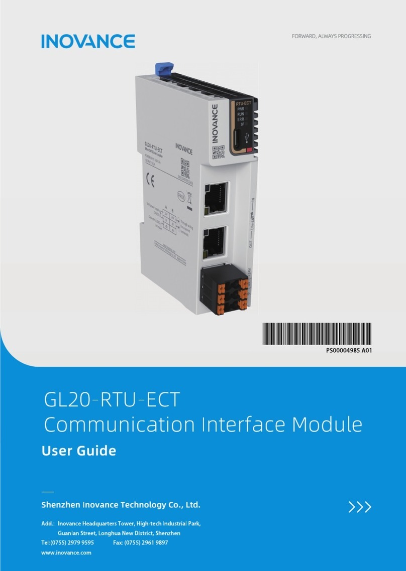
Inovance GR10-EC-6SW User manual

GR10-EC-6SW
6-Port EtherCAT Branch Module User Guide
Suzhou Inovance Technology Co., Ltd
Address: No.16 Youxiang Road, Yuexi, Wuzhong District, Suzhou
Service hotline: 4000-300124
Website: http://www.inovance.com
*19011256A01*
19011256A01

1
Preface
Introduction
Thank you for purchasing the GR10-EC-6SW 6-port EtherCAT branch module
developed and manufactured independently by Inovance. This product, which
provides one EtherCAT input port and ve EtherCAT output ports, is suitable for
star networked applications in multi-axis complex equipment and production
line networking.
This guide describes the specications, features and usage of the product. Please
read this guide carefully before using to ensure safety. You can obtain the latest
version on our website www.inovance.com.
Reader
This guide is intended for users who use or understand Inovance PLC products,
including: electrical engineers, software engineers, and system engineers.
Cautions for New User
For the users who use this product for the rst time, read the manual carefully. In
case of any question about functions or performance, do not hesitate to contact
the technical support personnel of Inovance to ensure correct use.
Revision History
Date Version Description
2019-11 A00 First release
2020-11 A01 Made minor corrections
Safety Instructions
■Safety Disclaimers
1. Before installing, using, and maintaining this equipment, read the safety information and
precautions thoroughly, and comply with them during operations.
2. To ensure the safety of humans and equipment, follow the signs on the equipment and all
the safety instructions in this user guide.
3. The“CAUTION,”“WARNING,”and "DANGER”signs are only supplements to the safety
instructions.
4. Use this equipment according to the designated environment requirements. Damage caused

2
by improper usage is not covered by warranty.
5. Inovance shall take no responsibility for any personal injuries or property damage caused by
improper usage.
■ Safety Levels and Denitions
WARNING
: Indicates that failure to comply with the notice may result in severe
personal injuries or even death.
CAUTION
: The“CAUTION”sign indicates that failure to comply with the notice may result
in minor or moderate personal injury or damage to the equipment.
Please keep this guide well so that it can be read when necessary and forward this guide to the
end user.
Control system design
WARNING
◆ Provide a safety circuit outside the PLC so that the control system can still work safely once
external power failure or PLC fault occurs.
◆ Add a fuse or circuit breaker because the module may smoke or catch re due to long-time
overcurrent caused by operation above rated current or load short-circuit.
CAUTION
◆An emergency stop circuit, a protection circuit, a forward/reverse operation interlocked circuit,
and a upper position limit and lower position limit interlocked circuit must be set in the
external circuits of PLC to prevent damage to the machine.
◆To ensure safe operation, for the output signals that may cause critical accidents, please design
external protection circuit and safety mechanism.
◆ Once PLC CPU detects abnormality in the system , all outputs may be closed; however, when
a fault occurs in the controller circuit, the output may not be under control. Therefore, it is
necessary to design an appropriate external control circuit to ensure normal operation.
◆If the PLC's output units such as relays or transistors are damaged, the output may fail to switch
between ON and OFF states according to the commands.
◆ The PLC is designed to be used in indoor electrical environment (overvoltage category II). The
power supply must have a system-level lightning protection device, assuring that overvoltage
due to lightning shock cannot be applied to the PLC's power supply input terminals, signal
input terminals and output terminals and so forth, so as to avoid damage to the equipment.

3
Installation
WARNING
◆Installation must be carried out by the specialists who have received the necessary electrical
training and understood enough electrical knowledge.
◆Disconnect all external power supplies of the system before removing/installing the module.
Failure to do so may result in electric shock, module fault or malfunction.
◆ Do not use the PLC where there are dust, oil smoke, conductive dust, corrosive or combustible
gases, or exposed to high temperature, condensation, wind & rain, or subject to vibration and
impact. Electric shock, re and malfunction may also result in damage or deterioration to the
product.
◆ The PLC is open-type equipment that must be installed in a control cabinet with lock (cabinet
housing protection > IP20). Only the personnel who have received the necessary electrical
training and understood enough electrical knowledge can open the cabinet.
CAUTION
◆ Prevent metal lings and wire ends from dropping into ventilation holes of the PLC during
installation. Failure to comply may result in re, fault and malfunction.
◆Ensure there are no foreign matters on ventilation surface. Failure to comply may result in poor
ventilation, which may cause re, fault and malfunction.
◆Ensure the module is connected to the respective connector securely and hook the module
rmly. Improper installation may result in malfunction, fault or fall-o.
Wiring
WARNING
◆Wiring must be carried out by personnel who have received the necessary electrical training
and understood enough electrical knowledge.
◆Disconnect all external power supplies of the system before wiring. Failure to comply may
result in electric shock, module fault or malfunction.
◆Install the terminal cover attached to the product before power-on or operation after wiring is
completed. Failure to comply may result in electric shock.
◆ Perform good insulation on terminals so that insulation distance between cables will not
reduce after cables are connected to terminals. Failure to comply may result in electric shock or
damage to the equipment.

4
CAUTION
◆ Prevent dropping metal lings and wire ends drop into ventilation holes of the PLC at wiring.
Failure to comply may result in re, fault and malfunction.
◆ The external wiring specication and installation method must comply with local regulations.
For details, see the wiring section in this guide.
◆ To ensure safety of equipment and operator, use cables with sucient diameter and connect
the cables to ground reliably.
◆Ensure that all cables are connected to the correct interface. Failure to comply may result in
module and external equipment fault.
◆ Tighten bolts on the terminal block in the specied torque range. If the terminal is not tight,
short-circuit, re or malfunction may be caused. If the terminal is too tight, fall-o, short-circuit,
re or malfunction may be caused.
◆If the connector is used to connect with external equipment, perform correct crimping or
welding with the tool specied by manufacturer. If connection is in poor contact, short-circuit,
re or malfunction may be caused.
◆A label on the top of the module is to prevent foreign matters entering the module. Do not
remove the label during wiring. Remove it before operation for ventilation.
◆Do not bundle control wires, communication wires and power cables together. They must be
run with distance of more than 100 mm. Otherwise, noise may result in malfunction.
◆Select shielded cable for high-frequency signal input/output in applications with serious
interference so as to enhance system anti-interference ability.
Operation and Maintenance
WARNING
◆ Maintenance & inspection must be carried out by qualied personnel.
◆Do not touch the terminals while the power is on. Failure to comply may result in electric shock or malfunction.
◆Disconnect all external power supplies of the system before cleaning the module or re-
tightening screws on the terminal block or screws of the connector. Failure to comply may
result in electric shock.
◆Disconnect all external power supplies of the system before removing the module or connecting/
removing communication wirings. Failure to comply may result in electric shock or malfunction.
CAUTION
◆ Get with the guide and ensure safety before online modication, forcible output, and RUN/
STOP operation.
◆Disconnect the power supply before installing/removing the extension card.
Disposal
CAUTION
◆Dispose of the product as industrial waste.
5
1 Product Information
Model Number and Nameplate
GR10-EC-6SW
3GXQ 9KXOKY
10
圔圓圃
3GXQ *KYIXOVZOUT
G
3GXQ ,[TIZOUT
EtherCATIUSS[TOIGZOUT
EC
General Module
R
8KSUZKSUJ[RK
3GXQ )NGTTKR
6-channel
6
(XGTIN
SW
.PEFM
3BUFEJOQVU
3BUFEPVUQVU
4FSJBM/P
/BNFQMBUF
.0%&-盘(3&$48
108&3*/165盘7%$N"
065165盘/0/&
9999999999999999
7FSTJPO/P
7&399999
9999999999999999
Figure 1 Description of model number and nameplate
Model Category Description Applicable
Model
GR10-EC-6SW
Remote
EtherCAT
branch
module
Remote EtherCAT branch module,
1 input, 5 outputs
Refer to the
PLC functions

6
External Interface
Figure 2 Module interfaces
No. Interface Name Function
① Power indicator PWR Green ON when power supply is switched
on
②EtherCAT input
interface IN Port1, EtherCAT output interface for connecting
front-end EtherCAT master
③EtherCAT Output
interface
X2 Port2, EtherCAT output interface for connecting
back-end EtherCAT slaves
X3 Port3: EtherCAT output interface for connecting
back-end EtherCAT slaves
X4 Port4, EtherCAT output interface for connecting
back-end EtherCAT slaves
X5 Port5: EtherCAT output interface for connecting
back-end EtherCAT slaves
X6 Port6: EtherCAT output interface for connecting
back-end EtherCAT slaves
④24 V power input
terminal For module power supply input

7
General Specications
Item Specications
Rated operating voltage 24 VDC (20.4 VDC to 28.8 VDC) (–15% to +20%)
Internally consumed current Approx. 160 mA
Communication protocol EtherCAT industrial real-time bus protocol
EtherCAT channel 1 input and 5 outputs
Max. comm. speed 100 Mbps
Network port/network cable Standard network port with Cat 5e network
cables, cable length not exceeding 100 meters
Operating temperature -10-55℃
Storage temperature -25-70℃
Humidity 10–95%, no-condensation
EtherCAT Communication Specications
Item Specications
Communication protocol EtherCAT industrial real-time bus protocol
Synchronization mode DC-distributed clock
Duplex mode Full duplex
Max. communication speed 100 Mbit/s (100Base-TX)
Topological structure Star
Branch module cascading Supported
Cable recognition Auto MDI/MDIX

8
2 Mechanical Design Reference
Mounting Dimensions
53.2
90
88.5
97.5
Figure 3 Mounting dimensions diagram (in mm)
3 Electrical Design Reference
Cable Preparation
$BCMFDPOOFDUPS1$QSPOH
"8($BUFTIJFMEFEUXJTUFEQBJS
$BCMFDPOOFDUPS1$QSPOH
Figure 4 EtherCAT cable preparation
4IJFMEFEDBCMF 6OTIJFMEFEDBCMF
Use Cat 5e shielded twisted pair (STP) cables, with injection molded and iron
shelled connector.

9
■Signal pins
Pin Signal Signal Direction Signal Description
1TD+ Output Data transmission+
2. TD- Output Data transmission-
3RD+ Input Data reception+
4-- -- Not used
5-- -- Not used
6RD- Input Data reception–
7 -- -- Not used
8-- -- Not used
■Length requirements:
According to FastEthernet technology, when an EtherCAT bus is used, the length
of the cable between the devices must not exceed 100 meters. Exceeding this
length will attenuate the signal and aect communication.
■Technical requirements:
100% continuity test, no short circuit, open circuit, misalignment and poor contact.
Use a shielded cable as the EtherCAT bus for network data transmission, with the
following recommended specications:
Item Specications
Cable type Flexible crossover cable, S-FTP, Cat 5e
Complied standards: EIA/TIA568A, EN50173, ISO/IEC11801
EIA/TI Abulletin TSB, EIA/TIA SB40-A&TSB36
Conductor cross section AWG26
Conductor type Twisted pair
Pair 4
Communication Wiring
■EtherCAT connection
Insert the cable connector into the EtherCAT port of the branch module until you
hear a click sound.
Removal: press the release tab of the connector to pull out the connector and

10
module horizontally.
■Wiring of the communication system
The EtherCAT branch module can connect multiple EtherCAT slave devices. The
system wiring diagram is shown below:
&UIFS$"5NBTUFS
1-$NBJOVOJU
&UIFS$"5
DBCMF
108&3
3JTLPGFMFDUS JD T IPDL
【㏅ 巫䤶
&UIFS$"5DPNNNPEVMF
&UIFS$"5
DBCMF
#SBODINPEVMF
*4/
&UIFS$"5DBCMF
4FSWPNPUPS
&ODPEFSDBCMF
.PUPSNBJODJSDVJUDBCMF
Figure 5 Wiring of the communication system

11
NOTE
To protect the communication cable from any tension and to ensure
communication stability, x the cable end which is near the device
before EtherCAT communication.
Conguration and use
1) When using this branch device, run all EtherCAT slaves (including the two
stations of this branch device) with an alias, so that an abnormal branch will
not aect the others.
2) The data ow priority of a 6-way branch device interface is X2>X3>X4>X5>X6, that is,
any slave on the X2 branch has priority over all slaves on the X3 branch.
3) The DC mode is enabled by default. That is, the branch device has been congured
as an EtherCAT slave in DC mode.
4) The branch device allows cascade, and the allowable number of nodes is not
restricted by the device.
5) Each branch device occupies two EtherCAT slave station numbers.
Fault Indication and Solutions
When the module fails, the user can check the signal status through the LED
indicator and take corresponding measures:
LED indicator
Indication Cause Solution
PWR Link/
Act
OFF OFF Power
failure
1. The power supply
is not connected
2. Internal circuit fault
1. Check power supply
connection
2. Replace the branch
module
ON OFF
Connection
not
established
1. The
communication cable
is disconnected or
short-circuited
2. Hardware fault of
the branch module
3. The master station
is not started
1. Check cable connection.
If cable breakage or short
circuit is found, replace the
communication cable
2. Replace the branch
module
③ Check the status of the
master

12
Warranty Agreement
The warranty period of the product is 18 months (The period is subject to the
date information indicated by the barcode on the product, or the terms and
conditions of the purchase contract if otherwise specied). During the warranty
period, if the product fails or is damaged under the condition of normal use by
following the instructions, Inovance will be responsible for free maintenance.
Within the warranty period, maintenance will be charged for the damages due to
the following causes:
6) Improper use or uninstallation/repair/modication without prior permission
7) Fire, ood, abnormal voltage, other disasters, and secondary disasters
8) Hardware damage caused by dropping or transportation after procurement
9) Failure to operate the product by observing the User Manual provided by
Inovance
10) Faults and damages caused by factors outside of the product (such as
peripheral devices)
If there is any failure or damage to the product, correctly ll out the Product
Warranty Card.
The maintenance fee is charged as the latest Maintenance Price List of Inovance.
The Product Warranty Card is not re-issued. Keep the card and present it to the
maintenance personnel when seeking maintenance.
If there is any problem during the service, contact us or our agent directly.
You are assumed to agree on terms and conditions of this warranty agreement by
purchase of the product. This agreement shall be interpreted by Inovance.
Table of contents
Other Inovance Control Unit manuals

Inovance
Inovance GL10-2PH User manual

Inovance
Inovance GL20-4AD User manual

Inovance
Inovance GL20-RTU-ECT User manual

Inovance
Inovance GL10-0032ETN User manual

Inovance
Inovance GL20-0800END User manual

Inovance
Inovance AM600-4PT User manual

Inovance
Inovance GR10-2PHE User manual

Inovance
Inovance WL432 Series Installation instructions

Inovance
Inovance GL10-PS2 User manual

Inovance
Inovance IMC30-6G Series User manual