HBK K3607 User manual
K3607
ENGLISH DEUTSCH
Operating Manual
Bedienungsanleitung

Hottinger Brüel & Kjaer GmbH
Im Tiefen See 45
D-64293 Darmstadt
Tel. +49 6151 803-0
Fax +49 6151 803-9100
www.hbkworld.com
Mat.:
DVS: A00833 03 X00 02
10.2023
EHottinger Brüel & Kjaer GmbH
Subject to modifications.
All product descriptions are for general information
only. They are not to be understood as a guarantee of
quality or durability.
Änderungen vorbehalten.
Alle Angaben beschreiben unsere Produkte in allge
meiner Form. Sie stellen keine Beschaffenheits- oder
Haltbarkeitsgarantie dar.

K3607
ENGLISH DEUTSCH
Operating Manual

K3607
TABLE OF CONTENTS
2
TABLE OF CONTENTS
1 Safety instructions 3................................................
2 Symbols on the product 5............................................
3 Fields of application 6...............................................
4 Connections 7......................................................
5 Calibrating the measurement chain 8..................................
6 Working standard calibration of the K3607 9...........................
7 Effect of cable resistance 10..........................................
8 Pin assignment 11...................................................

3
K3607
SAFETY INSTRUCTIONS
1 SAFETY INSTRUCTIONS
Appropriate use
The K3607 calibration instrument is to be used exclusively for measurement tasks and
directly related control tasks. Use for any purpose other than the above shall be deemed
to be not in accordance with the regulations.
In the interests of safety, the instrument should only be operated as described in the
Operating Manual. It is also essential to comply with the legal and safety requirements
for the application concerned during use. The same applies to the use of accessories.
Conditions on site
SProtect the device from direct contact with water.
SProtect the device from moisture and humidity or weather conditions such as rain,
snow.
SDo not expose the device to direct sunlight.
SPlease observe the permissible maximum ambient temperatures and humidity stated
in the specifications.
SThe device must not be modified from the design or safety engineering point of view
except with our express agreement. Any modification shall exclude all liability on our
part for any damage resulting therefrom.
In particular, any repair or soldering work on motherboards is prohibited. When
exchanging complete modules, use only original parts from HBM.
SInstall the device so that it can be disconnected from the supply voltage at any time
without difficulty.
SThe device is maintenance-free.
SBefore cleaning, disconnect all connections.
SClean the housing with a soft, slightly damp (not wet!) cloth. You should never use
solvents, since these could damage the labeling.
SWhen cleaning, ensure that no liquid gets into the module or connections.
SIn accordance with national and local environmental protection and material recovery
and recycling regulations, old equipment that can no longer be used must be disposed
of separately and not with normal household garbage.
Qualified personnel
Qualified personnel means persons entrusted with the installation, assembly, commis
sioning and operation of the product, who possess the appropriate qualifications for their
function.
This includes people who meet at least one of the three following requirements:

K3607
SAFETY INSTRUCTIONS
4
SKnowledge of the safety concepts of automation technology is a requirement and, as
project personnel, you must be familiar with these concepts.
SAs automation plant operating personnel, you have been instructed how to handle the
machinery. You are familiar with the operation of the equipment and technologies
described in this documentation.
SAs commissioning engineers or service engineers, you have successfully completed
the training to qualify you to repair the automation systems. You are also authorized
to activate, ground and label circuits and equipment in accordance with safety engi
neering standards.
It is also essential to comply with the legal and safety requirements for the application
concerned during use. The same applies to the use of accessories.
The device must only be installed by qualified personnel, strictly in accordance with the
specifications and with the safety requirements and regulations listed below.
Maintenance and repair work on an open device with the power on may only be carried
out by trained personnel who are aware of the dangers involved.
Working safety
SMaintenance and repair work on an open device with the power on may only be
carried out by trained personnel who are aware of the dangers involved.
SAutomation equipment and devices must be installed in such a way that adequate
protection or locking against unintentional actuation is provided (e.g. access checks,
password protection, etc.).
Additional safety precautions
Additional safety precautions must be taken in plants where malfunctions could cause
major damage, loss of data or even personal injury. In the event of a fault, these
precautions establish safe operating conditions.
The scope of supply and performance of the device only covers a small area of
measurement technology. In addition, equipment planners, installers and operators
should plan, implement and respond to the safety engineering considerations of
measurement technology in such a way as to minimize remaining dangers. On-site
regulations must be complied with at all times. There must be reference to the remaining
dangers connected with measurement technology.
General dangers of failing to follow the safety instructions
The device is a state of the art unit and as such is reliable. The module may give rise to
dangers if it is inappropriately installed and operated by untrained personnel.
5
K3607
SAFETY INSTRUCTIONS
2 SYMBOLS ON THE PRODUCT
CE mark
The CE mark enables the manufacturer to guarantee that the
product complies with the requirements of the relevant EC direc
tives (the declaration of conformity is available at
http://www.hbm.com/HBMdoc
).
Statutory marking requirements for waste disposal
National and local regulations regarding the protection of the
environment and recycling of raw materials require old equip
ment to be separated from regular domestic waste for disposal.
For more detailed information on disposal, please contact the
local authorities or the dealer from whom you purchased the
product.

K3607
FIELDS OF APPLICATION
6
3 FIELDS OF APPLICATION
The K 3607 calibration instrument can be used to calibrate measuring amplifiers or mea
surement chains without imposing a mechanical quantity on the SG transducers belong
ing to the measurement chain.
For this purpose the calibration instrument is equipped with a high‐precision resistance
network in star configuration, designed to simulate 350‐ΩSG full‐bridge transducers.
The extremely low self‐capacitance and self‐inductance of the inbuilt precision resistors
place the calibration instrument in accuracy class 0.025.
When an appropriate measuring amplifier is used, the calibration instrument can be oper
ated in six‐wire circuit for balancing the ohmic and capacitive effects of long measure
ment cables.
K 3607 Front panel
S1
S2
S3
Calibration valid at
end of cable
(KAB0238A−3).
S1 = polarity switch
S2 = calibration step switch
S3 = calibration value switch

7
K3607
CONNECTIONS
4 CONNECTIONS
The connector cable between the calibration instrument and the measuring amplifier is
connected either to the 7‐pin Amphenol connector MS 3102 A16S‐1P (St1) or to the 5‐pin
S3 (Bu 1 . . . Bu 5).
The contact assignment is shown in Fig. 6.1. The Amphenol connection is provided for a
six‐wire circuit. If the intention is to connect a six‐wire circuit to the pin terminals, connec
tions C and F on the measuring amplifier must both be connected to Bu3 on the calibra
tion instrument, and connections B and G must both be connected to Bu2.

K3607
CALIBRATING THE MEASUREMENT CHAIN
8
5 CALIBRATING THE MEASUREMENT CHAIN
SConnect the calibration instrument to the measurement chain you wish to calibrate in
place of the 350‐ΩSG transducer. If there is an extension cable on the measuring
amplifier, leave it in place in order to capture the ohmic and capacitive cable effects.
SUse S1 to preselect the desired polarity of the measurement signal.
SSet S2 (calibration step switch) to zero.
SIf necessary switch the measuring amplifier to full bridge (K 3607 operates as a full
bridge).
SBalance the measuring amplifier and subsequent instruments to zero in accordance
with their operating manuals and if necessary carry out capacitance adjustment.
SUse the calibration value switch S3 and the calibration step switch S2 to set the
desired calibration signal:
Calibration
value in
mV/V
Calibration step1) in %
0 10 20 30 40 50 60 70 80 90 100
0.5 0 0.05 0.1 0.15 0.2 0.25 0.3 0.35 0.4 0.45 0.5
1.0 0 0.1 0.2 0.3 0.4 0.5 0.6 0.7 0.8 0.9 1.0
2.0 0 0.2 0.4 0.6 0.8 1.0 1.2 1.4 1.6 1.8 2.0
5.0 0 0.5 1.0 1.5 2.0 2.5 3.0 3.5 4.0 4.5 5.0
10.0 0 1.0 2.0 3.0 4.0 5.0 6.0 7.0 8.0 9.0 10.0
Tab. 1.1 Calibration signal in mV/V depending on value switch setting of K3607
1) Effect of the calibration step switch (S2): The grading error for the percentage steps as set out in
the specifications will be maintained for every step if the internal resistance Ri of the bridge
excitation source plus cable is v1Ω. For an internal resistance Ri v4Ωthe error in the calibration
steps is kept at between 0 and 50 %. For a six‐wire circuit the tolerances are maintained if the
excitation voltage to the K 3607 is readjusted precisely enough.
SSet the measuring amplifier to the desired output signal in accordance with its operat
ing manual. In principle the measuring amplifier should be calibrated in the measuring
range you intend to use for measurement. If the measuring range of the amplifier is
changed, the switching error needs to be taken into consideration.

9
K3607
WORKING STANDARD CALIBRATION OF THE K3607
6 WORKING STANDARD CALIBRATION OF THE K3607
The K 3607 is calibrated in the factory under the following conditions:
SAmbient temperature: + 23 °C
SConnector cable: KAB0238A-3 (included in the list of components supplied), cable
length = 3 meters
SCross‐section of each bridge excitation wire 1.5 mm2
SInternal excitation voltage resistance: ≤1 Ω

K3607
EFFECT OF CABLE RESISTANCE
10
7 EFFECT OF CABLE RESISTANCE
The cable effect for KAB0238A‐3 cable is calibrated in at the factory. This applies to four‐
and six‐wire circuit at the end of the 3‐meter long cable.
On subsequent connection in four‐wire circuit, the output signal is reduced by the K factor
due to the resistance of the excitation wires.
The K factor is calculated as follows:
Bridge resistance)
The resistance value of an excitation wire is used for the r term. In the case of
KAB0238A‐3 cable this resistance r = 0.0118 Ω. According to the formula (1) this gives a
value of 0.99993 for the K factor. This means an absolute calibration error of 0.007% if
KAB0238A‐3 is not used.
A switching step error also occurs. Depending on the position of switch S2 the internal
resistance of the K 3607 alters slightly, as does the effective excitation voltage due to the
cable resistance r.
The grading error of the percentage steps increases by some 0.02% at 10 Ω of cable con
ductor resistance.
When connecting a six‐wire circuit the cable effect is corrected and the K factor = 1. No
additional grading error occurs (internal excitation voltage resistance < 1 Ω).
If KAB0238A‐3 cable is not used, an absolute calibration error of the corresponding size
occurs. This means the output signal is increased by a factor of K = 1.00007.
11
K3607
PIN ASSIGNMENT
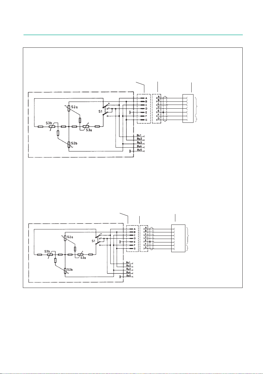
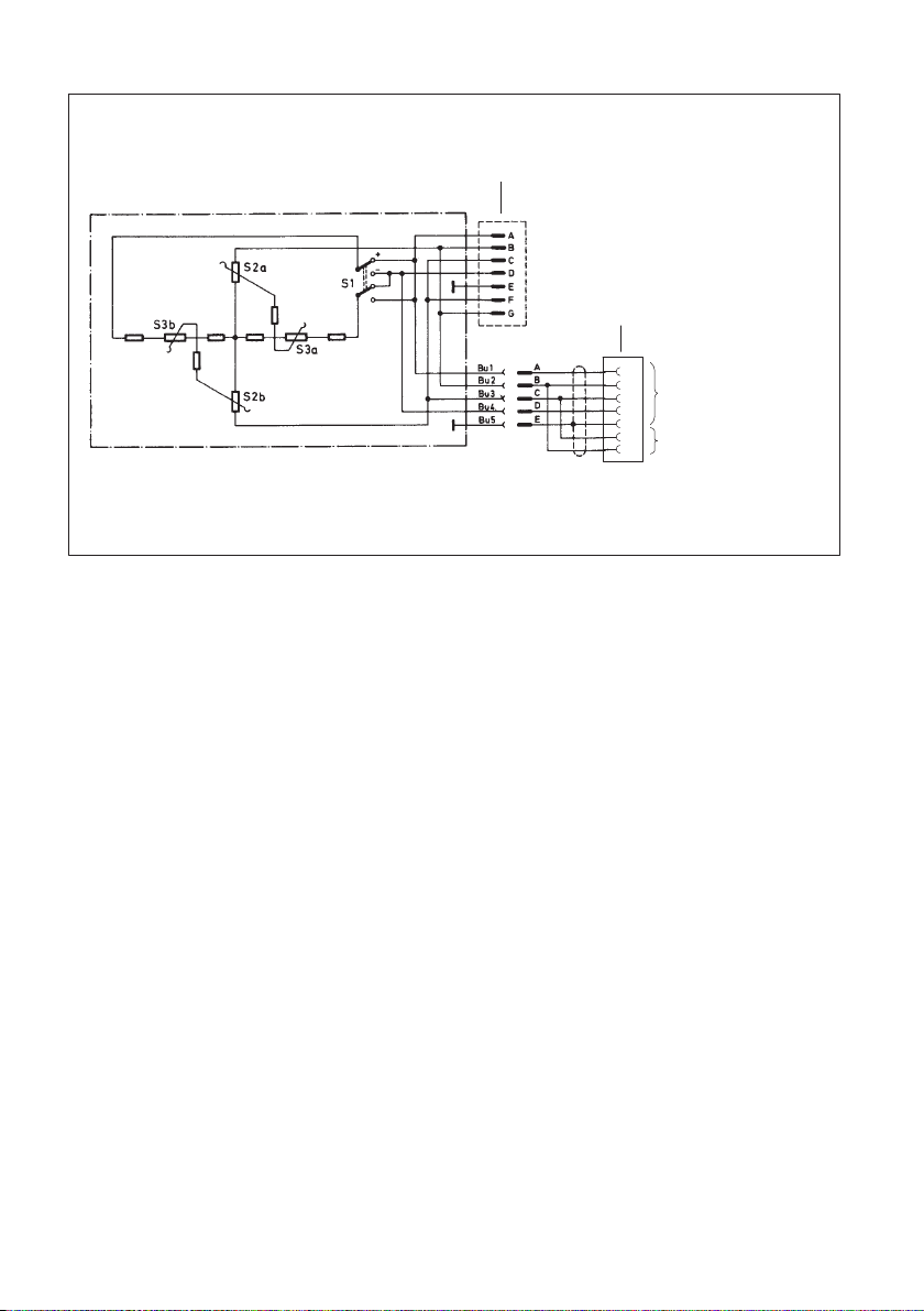
8 PIN ASSIGNMENT
A
B
C
D
E
F
G
MS3102A 16S-1P MS3106A 16S-1S MS3106A 16S-1P
8
5
6
15
Hsg.
13
12
Cable to measuring amplifier:
Amphenol connector - D sub connector
MS3102A 16S-1P MS3106A 16S-1S D-Sub 15p
St1
St1
To the amplifier
input
Sensor circuit to the
measuring amplifier,
six‐wire circuit only
Connection to 7‐pin Amphenol connector St1
To the amplifier
input
Sensor circuit to the
measuring amplifier,
six‐wire circuit only
Cable to measuring amplifier:
Amphenol connector - D sub connector
A: Measurement signal (+)
B: Excitation voltage (-)
C: Excitation voltage (+)
D: Measurement signal (-)
E: Shield
F: Sense lead (+)
G: Sense lead (-)
Fig. 1.1 Pin assignment Amphenol
K3607
PIN ASSIGNMENT
12
A
B
C
D
E
F
G
To the amplifier input
Sensor circuit to the
measuring amplifier,
six‐wire circuit only
Cable to measuring amplifier:
Pigtails - Amphenol connector
MS3102A 16S-1P
MS3106A 16S-1P
Connecting to pin terminals
St1
Fig. 1.2 Pin assignment pin terminals

K3607
ENGLISH DEUTSCH
Bedienungsanleitung

K3607
INHALTSVERZEICHNIS
2
INHALTSVERZEICHNIS
1 Sicherheitshinweise 3...............................................
2 Auf dem Gerät angebrachte Symbole 6................................
3 Anwendungsbereiche 7..............................................
4 Anschliessen 8.....................................................
5 Kalibrieren der Messkette 9..........................................
6 Werkskalibrierung des K3607 10.......................................
7 Einfluss des Kabelwiderstandes 11.....................................
8 Anschlussbelegung 12...............................................

3
K3607
SICHERHEITSHINWEISE
1 SICHERHEITSHINWEISE
Bestimmungsgemäße Verwendung
Das Kalibriergerät K3607 ist ausschließlich für Messaufgaben und direkt damit verbun
dene Steuerungsaufgaben zu verwenden. Jeder darüber hinausgehende Gebrauch gilt als
nicht bestimmungsgemäß.
Zur Gewährleistung eines sicheren Betriebes darf das Gerät nur nach den Angaben in der
Bedienungsanleitung betrieben werden. Bei der Verwendung sind zusätzlich die für den
jeweiligen Anwendungsfall erforderlichen Rechts‐und Sicherheitsvorschriften zu beach
ten. Sinngemäß gilt dies auch bei Verwendung von Zubehör.
Betriebsbedingungen
SSchützen Sie das Gerät vor direktem Kontakt mit Wasser.
SSchützen Sie das Gerät vor Feuchtigkeit und Witterungseinflüssen wie beispielsweise
Regen oder Schnee.
SSchützen Sie das Gerät vor direkter Sonneneinstrahlung
SBeachten Sie die in den technischen Daten angegebenen maximal zulässigen Umge
bungstemperaturen und die Angaben zur maximalen Luftfeuchte.
SDas Gerät darf ohne unsere ausdrückliche Zustimmung weder konstruktiv noch si
cherheitstechnisch verändert werden. Insbesondere sind jegliche Reparaturen, Lötar
beiten an den Platinen (Austausch von Bauteilen) untersagt. Bei Austausch gesamter
Baugruppen sind nur Originalteile von HBM zu verwenden.
SDas Gerät ist wartungsfrei.
STrennen Sie das Gerät von allen Strom‐ bzw. Spannungsversorgungen.
SReinigen Sie das Gehäuse mit einem weichen und leicht angefeuchteten (nicht nas
sen!) Tuch. Verwenden Sie auf keinen Fall Lösungsmittel, da diese die Beschriftung
oder das Gehäuse angreifen könnten.
SAchten Sie beim Reinigen darauf, dass keine Flüssigkeit in das Gerät oder an die An
schlüsse gelangt.
SNicht mehr gebrauchsfähige Geräte sind gemäß den nationalen und örtlichen
Vorschriften für Umweltschutz und Rohstoffrückgewinnung getrennt von regulärem
Hausmüll zu entsorgen.
Qualifiziertes Personal
Qualifizierte Personen sind Personen, die mit Aufstellung, Montage, Inbetriebsetzung und
Betrieb des Produktes vertraut sind und über die ihrer Tätigkeit entsprechende Qualifika
tionen verfügen.
Dazu zählen Personen, die mindestens eine der drei folgenden Voraussetzungen erfüllen:

K3607
SICHERHEITSHINWEISE
4
SIhnen sind die Sicherheitskonzepte der Mess‐ und Automatisierungstechnik bekannt
und sie sind als Projektpersonal damit vertraut.
SSie sind Bedienpersonal der Mess‐ oder Automatisierungsanlagen und sind im Um
gang mit den Anlagen unterwiesen. Sie sind mit der Bedienung der in dieser Dokumen
tation beschriebenen Geräte und Technologien vertraut.
SSie sind Inbetriebnehmer oder für den Service eingesetzt und haben eine Ausbildung
absolviert, die sie zur Reparatur der Automatisierungsanlagen befähigt. Außerdem
haben sie die Berechtigung, Stromkreise und Geräte gemäß den Normen der Sicher
heitstechnik in Betrieb zu nehmen, zu erden und zu kennzeichnen.
Bei der Verwendung sind zusätzlich die für den jeweiligen Anwendungsfall erforderlichen
Rechts‐ und Sicherheitsvorschriften zu beachten. Sinngemäß gilt dies auch bei Verwen
dung von Zubehör.
Das Gerät ist nur von qualifiziertem Personal ausschließlich entsprechend der techni
schen Daten in Zusammenhang mit den Sicherheitsbestimmungen und Vorschriften
einzusetzen.
Wartungs‐ und Reparaturarbeiten am geöffneten Gerät unter Spannung dürfen nur von
einer ausgebildeten Person durchgeführt werden, die sich der vorliegenden Gefahr be
wusst ist.
Sicherheitsbewußtes Arbeiten
SWartungs‐ und Reparaturarbeiten am geöffneten Gerät unter Spannung dürfen nur von
einer ausgebildeten Person durchgeführt werden, die sich der vorliegenden Gefahr
bewusst ist.
SGeräte und Einrichtungen der Automatisierungstechnik müssen so verbaut werden,
dass sie gegen unbeabsichtigte Betätigung ausreichend geschützt bzw. verriegelt
sind (z.B. Zugangskontrolle, Passwortschutz o.Ä.).
Zusätzliche Sicherheitsvorkehrungen
Bei Anlagen, die aufgrund einer Fehlfunktion größere Schäden, Datenverlust oder sogar
Personenschäden verursachen können, müssen zusätzliche Sicherheitsvorkehrungen
getroffen werden. Im Fehlerfall stellen diese Vorkehrungen einen sicheren Betriebszu
stand her.
Der Leistungs‐ und Lieferumfang des Gerätes deckt nur einen Teilbereich der Messtech
nik ab. Sicherheitstechnische Belange der Messtechnik sind zusätzlich vom Anlagenpla
ner/Ausrüster/Betreiber so zu planen, zu realisieren und zu verantworten, dass Restge
fahren minimiert werden. Jeweils existierende Vorschriften sind zu beachten. Auf
Restgefahren im Zusammenhang mit der Messtechnik ist hinzuweisen.

5
K3607
SICHERHEITSHINWEISE
Allgemeine Gefahren bei Nichtbeachten der Sicherheitshinweise
Das Gerät entspricht dem Stand der Technik und ist betriebssicher. Von dem Modul kön
nen Restgefahren ausgehen, wenn es von ungeschultem Personal unsachgemäß einge
setzt und bedient wird.

K3607
SICHERHEITSHINWEISE
6
2 AUF DEM GERÄT ANGEBRACHTE SYMBOLE
CE-Kennzeichnung
Mit der CE‐Kennzeichnung garantiert der Hersteller, dass sein
Produkt den Anforderungen der relevanten EG‐Richtlinien ent
spricht (die Konformitätserklärung finden Sie auf der Website
von HBM (www.hbm.com) unter HBMdoc).
Gesetzlich vorgeschriebene Kennzeichnung zur Entsorgung
Nicht mehr gebrauchsfähige Altgeräte sind gemäß den nationa
len und örtlichen Vorschriften für Umweltschutz und Rohstoff
rückgewinnung getrennt von regulärem Hausmüll zu entsorgen.
Falls Sie weitere Informationen zur Entsorgung benötigen, wen
den Sie sich bitte an die örtlichen Behörden oder an den Händler,
bei dem Sie das Produkt erworben haben.
Table of contents
Languages:
Other HBK Test Equipment manuals


