HBK 4231 User manual


Health and Safety Considerations
This apparatus has been designed and tested
in accordance with IEC/EN 61010–1 and
ANSI/UL 61010–1
Safety Requirements for
Electrical Equipment for Measurement,
Control and Laboratory Use
. This manual
contains information and warnings which
must be followed to ensure safe operation and
to retain the apparatus in safe condition.
Safety Symbols and Signal Words
Used
The apparatus will be marked with
this symbol when it is important that
you refer to the associated danger
or warning statement given in this
manual
The manual uses this symbol when a
danger or warning statement is
applicable
Hazardous Voltage/Electricity. Both
the apparatus and manual use this
symbol when there is a risk for shock
or electrocution
Hot Surface. This manual will use
this symbol when there is a risk for
burning or scolding
Earth (Ground) Terminal. The
apparatus will be marked with this
symbol when applicable
Protective Conductor Terminal. The
apparatus will be marked with this
symbol when applicable
Alternating Current. The apparatus
will be marked with this symbol
when applicable
Danger Signals an imminent hazardous
situation, which, if not avoided, will
result in death or serious injury
Warning Signals a possibly hazardous
situation, which, if not avoided, will
result in death or serious injury
Caution Signals a hazardous situation,
which, if not avoided, could result in
minor or moderate injury or
damage to the apparatus
Notice Signals a situation or practice that
requires attention, but does not
directly result in personal injury if
ignored
Risks and Hazards
Explosion Hazards
Danger: The apparatus is not
designed to be used in potentially
explosive environments. It should
not be operated in the presence of
flammable liquids or gases
Electrical Hazards
Warning: Any adjustment,
maintenance and repair of the open
apparatus under voltage must be
avoided as far as possible and, if
unavoidable, must be carried out
only by trained service
Caution: Switch off all power to equipment
before connecting or disconnecting
their digital interface. Failure to do
so could damage the equipment

Mechanical Hazards
Caution: Whenever it is likely that the correct
function or operating safety of the
apparatus has been impaired, it
must be made inoperative and be
secured against unintended
operation
Waste Handling
HBK complies with the EU’s Waste
Electrical and Electronic Equipment
(WEEE) Directive, which issues the
following waste handling instructions:
• Do not dispose of electronic
equipment or batteries as
unsorted municipal waste
• It is your responsibility to
contribute to a clean and healthy
environment by using the
appropriate local return and
collection systems
• Hazardous substances in
electronic equipment or batteries
may have detrimental effects on
the environment and human
health
• The symbol shown to the left
indicates that separate collection
systems must be used for any
discarded equipment or batteries
marked with that symbol
• Waste electrical and electronic
equipment or batteries may be
returned to your local HBK
representative or to Hottinger
Brüel & Kjær A/S for disposal

HBK has made every effort to ensure the
accuracy of the information contained in this
document. No responsibility is accepted for
any errors or omissions herein. It is the
responsibility of the user to ensure compliance
with any legal or statutory requirements in the
country of use. Data may change, as well as
legislation, therefore you are advised to obtain
copies of the most recently issued applicable
regulations, standards and guidelines.
All descriptions, illustrations and any other
information relating to the product are made by
way of general description, are approximate
only and for the general guidance and
information of the user. They cannot be
construed to imply representation or warranty
as to their accuracy, currency or completeness
and are not intended to form the basis of any
contract.
The information in this document does not
constitute a warranty, representation or
guarantee concerning the suitability or
performance of the product.
HBK shall not be liable for any loss whether
direct, indirect, incidental or consequential
arising from the use of or reliance upon any of
the content of this document, regardless of
whether such content has been accurate or
complete. HBK will not pay any damages
whether for loss or injury, punitive or
otherwise, because of use of or reliance upon
any of the content in this document.
Brüel & Kjær and all other trademarks, service
marks, trade names, logos and product names
are the property of Hottinger Brüel & Kjær A/S
(HBK) or a third-party company. Nothing in
this document may be construed as granting,
by implication, or otherwise any license or
right to use any of the trademarks without a
prior written permission of HBK or the owner
of such trademark.
© Hottinger Brüel & Kjær A/S. All rights
reserved.
Skodsborgvej 307 · DK-2850 Nærum · Denmark
Tel.: +45 77 41 20 00 · Fax: +45 45 80 14 05
For service and support, contact your nearest
HBK Global Customer Care (GCC) team:
+862161133674
France: [email protected]m,
+33169907101
Germany: GCC_DACH@hbkworld.com,
+49 421 1787 0
Italy: service.it@hbkworld.com,
+39 02 45471616
Japan: [email protected],
+81 3 6810 3500
+1 770 209 6907
Spain: [email protected],
+34 91 806 2610
+44 1223 389 800
To learn more about all HBK offerings, please
visit: www.hbkworld.com

Contents
CHAPTER 1
Introduction and Controls .................................................................. 1
1.1 Description.................................................................................... 1
1.2 On/Off Button............................................................................... 1
1.3 +20 dB Level Step.......................................................................... 2
1.4 Batteries........................................................................................ 3
1.5 Adapters........................................................................................ 4
CHAPTER 2
Operation........................................................................................... 7
2.1 Calibration Procedure................................................................... 7
2.2 Correction for Sound Field Influence ............................................ 8
CHAPTER 3
Characteristics.................................................................................. 11
3.1 Influence of Ambient Pressure ................................................... 11
3.2 Influence of Ambient Temperature ............................................ 12
3.3 Influence of Load Volume ........................................................... 13
3.4 Traceability ................................................................................. 13
3.5 Stability ....................................................................................... 13
3.6 Recalibration of the Calibrator ................................................... 13
3.7 Information for Pattern Evaluation Tests ................................... 14
3.8 How the Calibrator Works .......................................................... 14
3.9 Construction ............................................................................... 17
CHAPTER 4
Service and Repair............................................................................ 19
CHAPTER 5
Specifications ................................................................................... 21


1Sound Calibrator Type 4231
User Manual
Chapter 1
Introduction and Controls
1.1 Description
Sound Calibrator Type 4231 is used to calibrate sound level meters and
other sound measurement equipment. You can calibrate 1diameter
microphones directly and 1/2microphones using the adaptor
(UC 0210) supplied with the calibrator. With available adaptors (see
section 1.4.1), you can calibrate other microphones and instruments.
Fig.1.1 Sound Calibrator Type 4231
1.2 On/Off Button
Press the button (see Fig.1.1) to start the calibrator. To save the
batteries, the calibrator will automatically switch off again after a short
time if you have not fitted a microphone.
To switch the calibrator off, press the button again, or just remove
the calibrator from the microphone and wait a little before covering the
microphone opening.

+20 dB Level Step
2Sound Calibrator Type 4231
User Manual
When you want the calibrator to keep working, even when there is no
microphone or coupler fitted, you can defeat the automatic switch-off
function by putting the calibrator on a flat surface (such as a table) with
the opening facing downwards. This is useful if you are calibrating
several microphones one after the other.
✐Please note:
• If you are using a special adaptor or an adaptor smaller than 1/2, the
calibrator may not switch off automatically, even when there is no
microphone fitted. Switch it off by pressing the On/Off button.
• If the calibrator cannot maintain the specified sound pressure level, for
example because of a leakage at the adaptor, it will switch off
automatically.
• If the battery level is low, the calibrator will switch off when the button
is released. It may be forced to operate by holding down the On/Off
button as long as the calibrator is able to maintain the specified sound
pressure.
1.3 +20 dB Level Step
The button (see Fig.1.1) increases the sound pressure level by 20 dB
(to 114 dB). Using this button, you can calibrate in noisy environments
and check linearity.
If the calibrator is already switched on when you press the level step
button, the 114 dB sound pressure level is only produced as long as
you hold the button down.
To start the calibrator so that it works at the higher level all the time,
press the button and within 5 seconds press and hold down the
button until the 114 dB diode lights. The calibrator will now work at the
114 dB level until it is switched off.
✐Please note: With some special microphones and ear simulators, the
calibrator cannot maintain the 114 dB level, and will switch
off automatically.

Chapter 1 – Introduction and Controls
3Sound Calibrator Type 4231
User Manual
1.4 Batteries
The calibrator uses two 1.5 V IEC Type LR6 (American “AA”) size
batteries, HBK order number QB 0013. If you want to use other types of
batteries, we recommend that you choose only good quality alkaline
batteries.
When the batteries need changing, the calibrator stops working
continuously, and only works if you hold down the button. This
feature is an indication to you that the batteries are running low on
power. When this occurs, you must change the batteries before
performing a calibration, as the instrument will not give an accurate
SPL with weak batteries.
To keep the batteries and the calibrator in good condition:
• Take the batteries out if you are not going to use the calibrator for
a long period of time
• Always take old batteries out as soon as they become exhausted
• Replace both batteries at the same time, using two batteries of the
same type
1.4.1 To Replace the Batteries
1) Take the calibrator out of its case.
2) Remove the 1/2adapter. (see Fig.1.2).
3) Remove the two battery lids on each side of the 1/2adapter by
sliding them outwards.
4) Replace the batteries, making sure that the polarity of the batteries
is the same as the markings in each battery compartment.
5) Replace both battery compartment lids and the 1/2adapter on
the calibrator and put it back in its case.

Adapters
4Sound Calibrator Type 4231
User Manual
1.5 Adapters
Sound Calibrator Type 4231 is mainly intended to be used when
calibrating instruments with 1and 1/2microphones. With other
adapters, you can also use the calibrator for calibrating the
microphones and instruments shown in Table 1.1.
With some adapters, the calibration level and uncertainty may be
affected and you must manually add or subtract the stated calibration
level correction to compensate for this.
1.5.1 Calibrating 1Microphones
To calibrate a 1microphone, take the calibrator out of the case and
remove the green 1/2adapter (UC 0210), which is supplied with the
calibrator, by twisting it about 1/8 of a turn anti-clockwise as shown in
Fig.1.2. Then fit the microphone into the 1opening underneath.
Fig.1.2 Removing the 1/2
adapter
Chapter 1 – Introduction and Controls
5Sound Calibrator Type 4231
User Manual
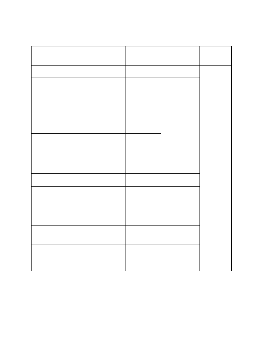
Table 1.1 Adapters and calibration level corrections for Sound Calibrator Type 4231
Brüel & Kjær Instrument Adapter Cal. Level
Correction Accuracy
1/2Microphones UC 0210 see Table 2.1
±0.2 dB
1/4Microphones DP 0775
0.0 dB
1/8Microphones DP 0774
Noise Dose Meter Type 4444
DP 0952
Logging Noise Dose Meter
Type 4445, 4445-E
Noise Dose Meter Type 4436 DP 0781a
Weatherproof Microphone Unit
Type 4184
(with Protection Tube UA 1072)
UC 0210b+1.7 dB
±0.5 dB
Sound Intensity Probe Sets DP 0888c+3.0 dB
Ear Simulator Type 4195
(low-leak, open ear sensitivity) DP 0939bd +4.2 dB
Ear Simulator Type 4195
(high-leak, open ear sensitivity) DP 0939bd –9.3 dB
Ear Simulator Type 4185
(open ear sensitivity) ––0.2dB
Ear Simulator Type 4157 DB 2015e+4.7 dB
HATS Type 4128-C UA 1546f+3.1 dB
a This adapter is delivered with the noise dose meter
b The 114 dB level cannot be used
c This only performs an SPL calibration. For intensity calibrations, use Sound Intensity
Calibrator Type 3541
d Adapter DP 0939 is delivered with Type 4195
e Adapter DB 2015 is delivered with Type 4157
f Adapter UA 1456 is delivered with Type 4128-C


Correction for Sound Field Influence
8Sound Calibrator Type 4231
User Manual
2) Press the microphone into the opening in the calibrator, see
Fig.2.1.
3) Press the button on the calibrator.
4) Adjust the sensitivity of measuring equipment to read the correct
value.
• See the relevant instrument user manual for the specific
calibration procedure.
• Refer to Table 1.1 for corrected calibration levels for various
types of microphones and adaptors
• Refer to Table 2.1 for corrected calibration levels for various
types of sound field.
5) Remove the calibrator from the microphone.
6) Switch off the calibrator, or wait for it to stop, before closing the
flap on its case.
2.2 Correction for Sound Field Influence
The sound level produced by the calibrator is 94.0 dB or 114.0 dB (re
20 µPa), when measured as a pressure field in a closed coupler.
However, if you are calibrating a microphone that is going to be used
for free- or random sound field measurements (for example,
microphones used on sound level meters) a small correction is
necessary. This correction compensates for the difference between the
microphone pressure sensitivity that you get with the calibrator, and
the sensitivity in the actual sound field (free or random) in which you
are using the microphone.
Table 2.1 shows the corrected calibration levels obtained with the
calibrator for different sound fields and for different sizes of
Brüel & Kjær microphones.
No correction is required when calibrating microphones which are
used for pressure measurements.

Chapter 2 – Operation
9Sound Calibrator Type 4231
User Manual
Table 2.1 Calibration levels for various sound fields and sizes of Brüel & Kjær microphones
(SPL at 94.0 dB level)
✐Please note:
• If you have increased the sound pressure level to 114 dB, by using the
level step button, please note that you should add 20 dB to the figures
in Table 2.1.
• A sound field correction may automatically be included in the
calibration routine of the sound level meter. If in doubt, consult the
instruction manual for your sound level meter. For Brüel & Kjær sound
level meters Type 2245, 2250, 2250-L and 2270, the correction is
included.
Sound
Field
Microphone
11/21/41/8
Free-field 93.70 dB 93.85 dB 94.00 dB
Random 94.00 dB
Pressure 94.00 dB

11Sound Calibrator Type 4231
User Manual
Chapter 3
Characteristics
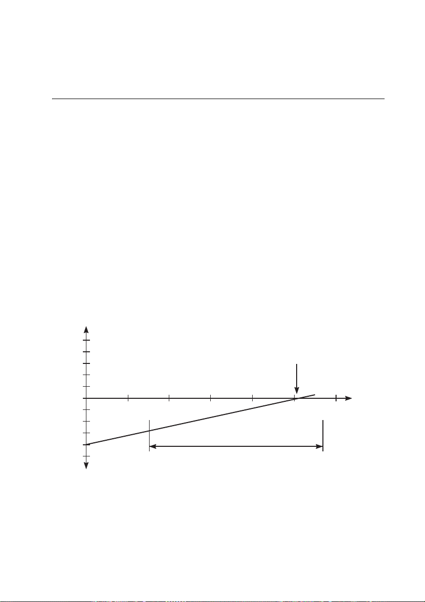
3.1 Influence of Ambient Pressure
For normal use, the influence of atmospheric pressure on the sound
pressure level produced by the calibrator is so small that you can ignore it.
Fig.3.1 shows the effect that variations in atmospheric pressure have
on the sound pressure level produced. It is a linear relationship caused
by changes in the sensitivity of the calibrator’s reference microphone
which varies directly with changes in static pressure.
Fig.3.1 Typical variation of sound pressure level as a function of static pressure at 23 °C
930279/2
0.05
60 70 80 90 100 11050
10865
Typical IEC 60942
Specificaon range
Calibraon point
101.3 kPa
Atmospheric
pressure
in kPa
Calibraon deviaon in dB
– 0.04
– 0.05
Influence of Ambient Temperature
12 Sound Calibrator Type 4231
User Manual
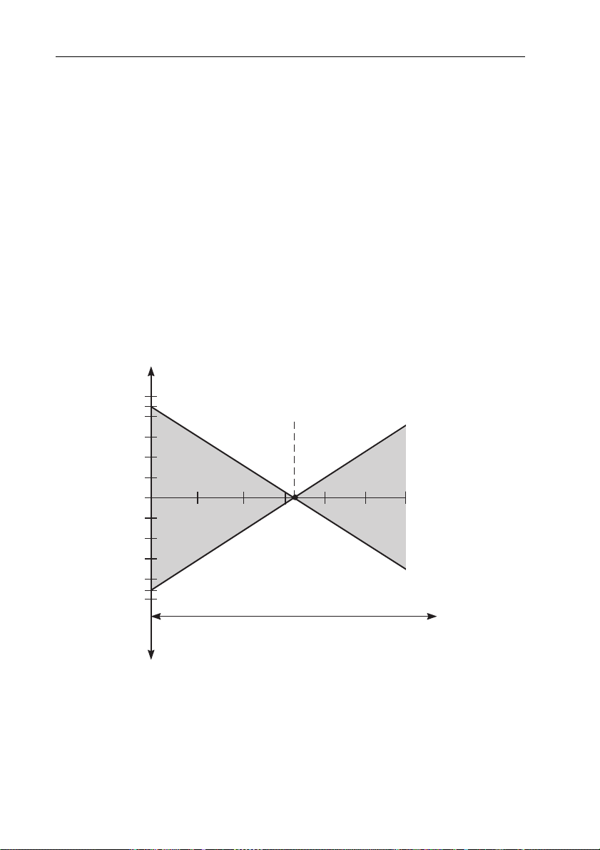
3.2 Influence of Ambient Temperature
Under normal conditions, the influence of changes in ambient
temperature on the sound pressure level produced by the calibrator is
so small that you can ignore it.
You can see the effect of ambient temperature changes in Fig.3.2.
These are mainly caused by variations in the reference microphone’s
sensitivity. The electronic compensation corrects for the main
influence of temperature on the microphone’s nominal sensitivity, and
the deviation is caused by the variation from this nominal value.
Fig.3.2 Typical calibration uncertainty at 101.3 kPa due to variation in ambient
temperature
930278/5
0.05
0
– 0.05
Calibraon
Deviaon
in dB
Calibraon
point
– 0.045
010 4030 50– 10
IEC 60942
Specificaon range
0.045
20
Ambient
temperature
in °C
Table of contents
Languages:
Other HBK Test Equipment manuals


