HBK Z30A User manual
Z30A
ENGLISH DEUTSCH
Mounting Instructions
Montageanleitung

Hottinger Brüel & Kjaer GmbH
Im Tiefen See 45
D-64293 Darmstadt
Tel. +49 6151 803-0
Fax +49 6151 803-9100
www.hbkworld.com
Mat.: 7-0111.0007
DVS: A02076 01 X00 03
05.2022
EHottinger Brüel & Kjaer GmbH
Subject to modifications.
All product descriptions are for general information
only. They are not to be understood as a guarantee of
quality or durability.
Änderungen vorbehalten.
Alle Angaben beschreiben unsere Produkte in allge
meiner Form. Sie stellen keine Beschaffenheits- oder
Haltbarkeitsgarantie dar.

Z30A
ENGLISH DEUTSCH
Mounting Instructions

Z30A
TABLE OF CONTENTS
2
TABLE OF CONTENTS
1 Safety instructions 3................................................
2 Markings used 5....................................................
2.1 The markings used in this document 5.................................
2.2 Symbols on the product 5............................................
3 Scope of supply 6...................................................
4 Application notes 7.................................................
5 Structure and mode of operation 8....................................
5.1 Measuring body 8...................................................
5.2 Housing 8.........................................................
5.3 Disturbance variables 8..............................................
6 Conditions on site 9.................................................
6.1 Ambient temperature 9..............................................
6.2 Moisture 9.........................................................
6.3 Air pressure 9......................................................
6.4 Chemical effects 9..................................................
7 Mechanical installation 10............................................
7.1 Important precautions during installation 10..............................
7.2 General installation guidelines 10.......................................
7.3 Mounting accessories for tensile/compressive loading 10..................
7.3.1 Installation drawing for compressive loading 14..........................
8 Electrical connection 15..............................................
8.1 Instructions for cabling 15.............................................
8.2 Pin assignment 15...................................................
8.3 TEDS transducer identification 16......................................
9 Specifications 17....................................................
10 Dimensions Z30A 20.................................................

3
Z30A
SAFETY INSTRUCTIONS
1 SAFETY INSTRUCTIONS
Use in accordance with the regulations
Z30A type force transducers are used for high‐precision force measurements and for
force reference measurements (transfer standard). Use for any additional purpose shall
be deemed to be not in accordance with the regulations.
In the interests of safety, the transducer should only be operated as described in the
Mounting Instructions. It is also essential to observe the appropriate legal and safety
regulations for the application concerned during use. The same applies to the use of
accessories.
The transducer is not a safety element within the meaning of its use as intended. Proper
and safe operation of this transducer requires proper transportation, correct storage,
assembly and mounting and careful operation and maintenance.
General dangers of failing to follow the safety instructions
The Z30A force transducer corresponds to the state of the art and is fail‐safe. The
transducers can give rise to remaining dangers if they are inappropriately installed and
operated by untrained personnel.
Everyone involved with the installation, commissioning, maintenance or repair of a force
transducer must have read and understood the Mounting Instructions and in particular
the technical safety instructions.
Remaining dangers
The scope of supply and performance of the transducer covers only a small area of force
measurement technique. In addition, equipment planners, installers and operators should
plan, implement and respond to the safety engineering considerations of force
measurement technique in such a way as to minimise remaining dangers. Prevailing
regulations must be complied with at all times. There must be reference to the remaining
dangers connected with force measurement technique.
Prohibition of own conversions and modifications
The transducer must not be modified from the design or safety engineering point of view
except with our express agreement. Any modification shall exclude all liability on our part
for any damage resulting therefrom.
Qualified personnel
These transducers are only to be installed by qualified personnel strictly in accordance
with the technical data and with the safety rules and regulations which follow. It is also
essential to observe the appropriate legal and safety regulations for the application
concerned. The same applies to the use of accessories.

Z30A
SAFETY INSTRUCTIONS
4
Qualified personnel means persons entrusted with the installation, fitting, commissioning
and operation of the product who possess the appropriate qualifications for their
function.
Conditions on site
Protect the transducer from damp and weather influences such as rain, snow, etc.
Maintenance
The Z30A force transducer is maintenance free.
Accident prevention
Although the specified nominal force in the destructive range is several times the full
scale value, the relevant accident prevention regulations from the trade associations
must be taken into consideration.

5
Z30A
MARKINGS USED
2 MARKINGS USED
2.1 The markings used in this document
Important instructions for your safety are specifically identified. It is essential to follow
these instructions in order to prevent accidents and damage to property.
Symbol Significance
WARNING This marking warns of a potentially dangerous situ
ation in which failure to comply with safety require
ments can result in death or serious physical injury.
CAUTION This marking warns of a potentially dangerous
situation in which failure to comply with safety
requirements can result in slight or moderate physical
injury.
Notice This marking draws your attention to a situation in
which failure to comply with safety requirements can
lead to damage to property.
Important
This marking draws your attention to important in
formation about the product or about handling the
product.
Tip
This marking indicates application tips or other
information that is useful to you.
Information
This marking draws your attention to information
about the product or about handling the product.
Emphasis
See …
Italics are used to emphasize and highlight text and
identify references to sections, diagrams, or external
documents and files.
2.2 Symbols on the product
CE mark
The CE mark enables the manufacturer to guarantee that the
product complies with the requirements of the relevant EU direc
tives (the declaration of conformity is available at
http://www.hbm.com/HBMdoc
).

Z30A
SCOPE OF SUPPLY
6
3 SCOPE OF SUPPLY
SForce transducer Z30A
SOperating Manual Z30A
Accessories (not included in the scope of supply)
SDKD calibration certificate according to ISO 376
Order no. K-CAL-FD
(Class 00 according to DIN EN10002-3 resp. ISO376 guaranteed
SKnuckle eyes ZGW/ZGOW
for 50 N to 1000 N: Order no. 1-U1R/200kg/ZGW
for 2 kN to 10 kN: Order no. 1-U2A/1t/ZGUW
SThrust piece
(recommended for precision measurements, for example ISO 376-Calibrations)
for 50 N to 1000 N Order no. 1-EDO3/1kN
for 2 kN to 10 kN Order no. 1-EDO4/50kN
SLoad button for compressive load
for 50 N to 1000 N: Order no. 1-U1R/200kg/ZL
for 2 kN to 10 kN: Order no. 3-9202.0140
SCable/plug
Order number Description
1-KAB139A-6 Kab 139A-6 connection cable , 6m, with Binder cable socket
and free ends
K-CAB-F Connection cable, freely configurable (cable length, plug at
amplifier end, etc.)
STransport case
for four Z30A force transducers and accessories
Order no. 1-Z30/Box

7
Z30A
APPLICATION NOTES
4 APPLICATION NOTES
Force transducer Z30A
Series Z30A precision force transducers measure tensile and compressive forces.
They measure static and quasi‐static forces with great accuracy and reproducibility and
therefore require judicious handling. You must be particularly vigilant when transporting
and installing the devices. If the transducers are dropped or jolted, permanent damage
could be caused.
Z30A force transducers complete with DKD certificate from HBM
Force transducer calibrated to guaranteed class 00 according to ISO 376.
As standard these transducers are calibrated in the tensile direction. On request they can
also be calibrated in the compressive direction to DKD standards.
The limits for permissible mechanical, thermal and electrical stresses are stated in the
specifications. Be sure to allow for them when planning, installing and operating the
measurement configuration .

Z30A
STRUCTURE AND MODE OF OPERATION
8
5 STRUCTURE AND MODE OF OPERATION
5.1 Measuring body
The measuring body comprises a system of measuring body with strain gages (double
bending beam principle).
5.2 Housing
The enclosure provides protection against splashes and minor impacts (IP50 degree or
protection per DIN EN60529).
5.3 Disturbance variables
Torsion, bending and transverse loads are disturbance variables and are therefore to be
avoided. If necessary they can be remedied with HBM mounting accessories (see
chapter 7.3 ).

9
Z30A
CONDITIONS ON SITE
6 CONDITIONS ON SITE
6.1 Ambient temperature
The effects of temperature on the zero signal and on the sensitivity are compensated. To
achieve optimal measurement results the nominal temperature range must be
maintained. Temperature‐induced measurement errors can be caused by uneven cooling
or heating (for example by radiant heat). A radiation shield and all‐round heat insulation
bring about marked improvements. They must not form a force shunt.
6.2 Moisture
Extreme humidity or a tropical climate should be avoided if this means that the classified
limit values are exceeded (degree of protection IP50 under DIN EN 60529).
6.3 Air pressure
Changes in air pressure have no effect on the force transducer since it is not hermetically
sealed.
6.4 Chemical effects
The aluminium enclosure of the transducer is protected by a powder coating. If used in
difficult environmental conditions (direct weather effects, contact with media which
encourage corrosion) additional protective measures should be employed by the user.

Z30A
MECHANICAL INSTALLATION
10
7 MECHANICAL INSTALLATION
7.1 Important precautions during installation
Streat the transducer gently
Sif measuring compressive forces, make sure there is a solid support structure
Sthe force‐introduction surfaces must be scrupulously clean and fully load‐bearing
Skeep to the depths of engagement for threaded rods or knuckle eyes
Sdo not overload the transducer.
WARNING
If there is a risk of breakage through overload on the transducer and thus a risk to persons,
additional safety measures are to be taken.
7.2 General installation guidelines
The measurement direction in which forces act on the transducer must be as precise as
possible.
WARNING
Torsion and bending moments, eccentric loading and transverse forces result in measure
ment errors and if limit values are exceeded, could destroy the transducer.
7.3 Mounting accessories for tensile/compressive loading
Knuckle eyes are available for installing with the Z30A (see page 24). These mounting
accessories prevent the introduction of torsional moments into the transducer. Using two
knuckle eyes will also exclude bending moments, shear loading and eccentric loading.
Knuckle eyes are mainly provided to deal with static tensile loading on the transducer.
For dynamic loading, Z30A transducers must be installed free from play. Knuckle eyes
have only limited application in the case of dynamic loading, since alternating dynamic
stress increases the play in the universal joints and falsifies the measured value. It also
produces a self‐amplifying load cycle which can destroy the knuckle eyes. The breaking
force is only 150% Fnom.
Thrust pieces EDO3/1kN or EDO4/50kN (see page 26) and two load buttons (see page
25) are available for introducing compressive forces.
11
Z30A
MECHANICAL INSTALLATION
Notes on mounting with knuckle eyes
1. Shaft diameter
When using a sensor with knuckle eyes mounted on one or both sides, make sure that the
shaft is the right size.
You will find the diameters of the knuckle eyes, suitable shafts and their recommended
tolerances in the table below
Knuckle eye Z30A
Knuckle eyes Nominal
diameter
Hole fitting
size
Recommended shaft
fitting size
1-U1R/200kg/ZGW 8 H7 g6
1-U2A/1t/ZGUW 12
Tab. 7.1 Recommended fitting sizes/tolerances for shaft and hole
Customer's construction
Customer's shaft holder
Shaft
Play based on recommended fitting
size, see Tab. 7.1 page 11
Threaded connector for mounting
on force transducers
Fig. 7.1 Example diagram of installation with knuckle eye
Z30A
MECHANICAL INSTALLATION
12
CAUTION
If a shaft with an overly small diameter is used, the bearing of the knuckle eye will be
subjected to linear load. This subjects the inner bearing shell to excessive load, which can
lead to damage and, if forces are high, can cause the knuckle eye bearing to break.
Select the shaft as recommended in the mounting instructions.
2. Distance between knuckle eye and shaft bearing
The shaft support must allow for suitable play between the knuckle eye and the shaft
bearing.
CAUTION
If there is too much distance between the knuckle eye and the shaft bearing, this generates
bending moments in the shaft, causing it to deform.
This deformation puts strain on points of the edges of the inner bearing shell, which can
cause the knuckle eye or shaft to suffer damage or break.
Select the play as recommended in the mounting instructions.
To determine the play between the knuckle eye and the shaft bearing, you can apply the
following rule of thumb:
Shaft diameter Play between knuckle eye and bearing
<30 mm 1/10 of the nominal diameter
Tab. 7.2 Rule of thumb for determining play between knuckle eye and shaft bearing
Based on this, recommendations for the play between the knuckle eye and shaft bearing
are as follows:
Knuckle eye Play between knuckle eye and shaft bearing
1-U1R/200kg/ZGW 0.8mm
1-U2a/1t/ZGUW 1.2mm
Tab. 7.3 Recommendations for play between knuckle eye and shaft bearing

13
Z30A
MECHANICAL INSTALLATION
Customer's construction
Customer's shaft holder
Recommended play,
see Tab. 7.3, page 12
Threaded connector for mounting
on force transducers
Shaft
Fig. 7.2 Example diagram of installation with knuckle eye
3. Shaft surface quality and hardness
The recommended surface roughness is ≤10 μm.
The shaft must have a minimum hardness of 50 HRC.
Z30A
MECHANICAL INSTALLATION
14
7.3.1 Installation drawing for compressive loading
F
Thrust piece
Load button
Transducer
Type Load button Thrust piece
Z30A/50N - 1000N 1-U1R/200kg/ZL 1-EDO3/1kN
Z30A/2kN - 10kN 3-9202.0140 1-EDO4/50kN

15
Z30A
ELECTRICAL CONNECTION
8 ELECTRICAL CONNECTION
8.1 Instructions for cabling
SAlways use shielded, low‐capacity measurement cable (HBM cables meet these
requirements).
SDo not lay measurement cable parallel to high‐voltage power lines or control circuits.
If this is not possible (e.g. in cable ducts) protect the measurement cable, e.g. with
armoured steel tube and maintain a minimum distance of 50 cm from the other
cables. High‐voltage power lines and control lines should be twisted (15 turns per
meter).
SAvoid stray fields of transformers, motors and contactors.
SDo not earth transducer, amplifier and display device more than once. All the devices
in the measurement chain are to be connected to the same earthed conductor.
SThe screen of the connection cable is connected to the transducer housing.
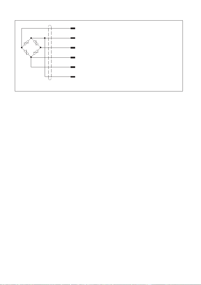
8.2 Pin assignment
Two 7‐pin male device connectors are located on the enclosure (male connectors, Series
723). To avoid creating force bypasses through the cable, you can use either the lower or
the lateral connector, depending on the configuration.
If the transducer is connected according to the following connection diagram then when
the transducer has compressive loading the output voltage at the measuring amplifier is
positive.
Pin on
Binder plug
Assignment
61
572
43
Binder series 723
Top view 1Measurement signal (+)
2Excitation voltage (-) (TEDS)
3Excitation voltage (+)
4Measurement signal (-)
5No function
6Sensor circuit (+)
7Sensor circuit (-) (TEDS)
Fig. 8.1 Male connector, series 723 (screwed)
Z30A
ELECTRICAL CONNECTION
16
WH (white)
BK (black)
RD (red)
BU (blue)
GN (green)
GY (grey)
Measurement signal (+) UA
Excitation voltage (+) UB
Sensor circuit (-) (TEDS)
Sensor circuit (+)
Excitation voltage (-) UB(TEDS)
Measurement signal (-) UA
Cable shield, connected to housing
Fig. 8.2 Pin assignment of plug and KAB139A-6 connection cable
8.3 TEDS transducer identification
TEDS stands for ”Transducer Electronic Data Sheet”.
An electronic data sheet is stored in the transducer as defined in the IEEE 1451.4
standard, making it possible for the measuring amplifier to be set up automatically. A
suitably equipped amplifier imports the transducer characteristics (electronic data
sheet), translates them into its own settings and measurement can start.
At connection PIN 7 (to ground at PIN 2), there is a digital identification system available.
The basis for this is a 1‐wire EEPROM DS2433, from Maxim/Dallas.
HBM provides you with the TEDS Editor for storing your data. This is included in the
software for the MGCplus Setup Assistant (see TEDS operating manual “TEDS-module in
transducer” on our website at ww.hbm.com/TEDS).
The Editor also makes it possible to manage the different user rights, to protect the
fundamental transducer data from being inadvertently overwritten.

17
Z30A
SPECIFICATIONS
9 SPECIFICATIONS
Nominal (rated) force Fnom
N50 100 200 500 1000
kN 2 5 10
Accuracy values per ISO376
Accuracy information
in accordance with
ISO376 in the force
range of 20 % to 100 %
001)
Rel. reproducibility and
repeatability errors
(0.2Fnom to Fnom)
For a constant mount
ing position
b'
%
<±0.02
For varying mounting
positions b <±0.04
Rel. deviation from the
fitting curve (0.2Fnom
to Fnom)
fc<±0.02
Rel. zero error (zero
signal return) fo<±0.008
Rel. reversibility error
(0.2Fnom to Fnom)v <±0.06
Rel. non-linearity dlin <±0.03
Temperature coeffi
cient of sensitivity TCS%/
10K
<±0.02
Temperature coeffi
cient of zero signal TC0<±0.02
Rel. creep over 30
mins.
dcrF+
E% <±0.03
Effect of lateral forces
(lateral force 10% Fnom)dQ
%
<±0.03
Effect of eccentricity
per mm dE<0.03
Rated electrical output
Nominal (rated) output Cnom mV/V 2
Rel. sensitivity error
(pressure) dc% <±0.1

Z30A
SPECIFICATIONS
18
100050020010050N
Fnom
Nominal (rated) force
1052kN
Fnom
Nominal (rated) force
Rel. rated output varia
tion (tension/compres
sion)
dzd % <±0.1
Rel. zero signal
deviation ds,o mV/V <±0.2 <±0.1
Input resistance Re
Ω
>345 >690
Output resistance Ra300 … 500 600 … 800
Insulation resistance Ris >5·109
Reference excitation
voltage Uref
V
5
Operating range of the
excitation voltage BU,G 0.5 … 12
Temperature
Reference temperature tref
°C
+22
Nominal (rated)
temperature range
Bt,no
m+10 … +40
Operating temperature
range Bt,G -10 … +70
Storage temperature
range Bt,S -25 … +85
Characteristic mechanical quantities
Max. operating force FG
%
120 150
Force limit FL150
Breaking force FB250
Static lateral force limit FQ100 75 35 100 90 40
Torque limit MGN·m 1.5 3 5 5 5 80
Nominal (rated)
displacement Snom mm < 0.4 approx. 0.2
Fundamental frequency fGkHz 0.2 0.3 0.5 0.9 1.1 1.1 1.1 1.25
Rel. permissible oscil
lation stress Frb % 70
General information
Degree of protection in
accordance with
EN 60529
IP50
Other manuals for Z30A
1
Table of contents
Languages:
Other HBK Test Equipment manuals


