HBK AED 9101D User manual
AED
ENGLISH DEUTSCH
Operating Manual
Bedienungsanleitung

Hottinger Brüel & Kjaer GmbH
Im Tiefen See 45
D-64293 Darmstadt
Tel. +49 6151 803-0
Fax +49 6151 803-9100
www.hbkworld.com
Mat.:
DVS: A05803 01 X00 00
11.2021
EHottinger Brüel & Kjaer GmbH
Subject to modifications.
All product descriptions are for general information
only. They are not to be understood as a guarantee of
quality or durability.
Änderungen vorbehalten.
Alle Angaben beschreiben unsere Produkte in allge
meiner Form. Sie stellen keine Beschaffenheits- oder
Haltbarkeitsgarantie dar.

AED
Transducer Electronics 9101D, 9201B, 9301B,
9401A and 9501A
ENGLISH DEUTSCH
Operating Manual

AED
TABLE OF CONTENTS
2
TABLE OF CONTENTS
1 Safety Instructions 4................................................
2 Markings used 7....................................................
2.1 Markings used in this document 7.....................................
2.2 Symbols on the device 8.............................................
3 Overview 9.........................................................
3.1 Scope of supply 9...................................................
3.2 Method of operation and functions 9...................................
4 Mechanical construction 11...........................................
4.1 Mechanical construction of the AED9101D 11............................
4.2 Mechanical construction of the AED9201B 12............................
4.3 Mechanical construction of the AED9301B 13............................
4.4 Mechanical construction of the AED9401A 14............................
4.5 Mechanical construction of the AED9501A 15............................
5 Mechanical installation 16............................................
6 Electrical connection 17..............................................
6.1 Ground (GND) and shield wiring 17.....................................
6.2 Cable connection via the PG gland 19...................................
6.3 Transducer connection 20.............................................
6.3.1 6wire circuit (standard mode of operation) 20...........................
6.3.2 4wire circuit 20.....................................................
6.4 Connecting the supply voltage 23......................................
6.4.1 Power supply to AED9101D 23.........................................
6.4.2 Power supply to AED9201B 24.........................................
6.4.3 Power supply to AED9301B 24.........................................
6.4.4 Power supply to AED9401A 25.........................................
6.4.5 Power supply to AED9501A 25.........................................
7 Connecting interfaces and I/Os 26.....................................
7.1 Using several AEDs (bus mode) 26......................................
7.1.1 Connection variants with the RS-485 interface 26.........................
7.1.2 Connection to a CANopen/DeviceNet bus system 28......................
7.1.3 Connection to a PROFIBUS bus system 29...............................
7.1.4 Connection to the diagnostic bus 30....................................

3
AED
TABLE OF CONTENTS
7.2 AED9101D 31.......................................................
7.2.1 ConnectingRS-232, RS-422, RS-485 in a 2-wire or 4-wire configuration 31..
7.2.2 Connecting the diagnostic bus 32......................................
7.2.3 Connecting the digital input 33.........................................
7.3 AED9201B 34.......................................................
7.3.1 Connecting RS-232 or RS-485 in a 4-wire configuration 34................
7.3.2 Connecting the diagnostic bus 35......................................
7.3.3 Connecting digital inputs/outputs 35....................................
7.4 AED9301B 37.......................................................
7.4.1 Connection to the PROFIBUS 37........................................
7.4.2 Connecting the diagnostic bus 38......................................
7.4.3 Connecting digital inputs/outputs 38....................................
7.5 AED9401A 40.......................................................
7.5.1 Connecting CANopen or DeviceNet 40...................................
7.5.2 Connecting the diagnostic bus 41......................................
7.5.3 Connecting digital inputs/outputs 41....................................
7.6 AED9501A 43.......................................................
7.6.1 Connecting CANopen or DeviceNet 43...................................
7.6.2 Connecting the diagnostic bus 44......................................
7.6.3 Connecting the digital input 44.........................................
8 Technical Support 46.................................................
9 Maintenance 47.....................................................
10 Disposal and environmental protection 48...............................

AED
SAFETY INSTRUCTIONS
4
1 SAFETY INSTRUCTIONS
Intended use
The device is to be used exclusively for measurement tasks and directly related control
tasks within the operating limits detailed in the specifications. Use for any purpose other
than the above is deemed improper use.
Any person instructed to carry out installation, startup or operation of the device must
have read and understood the operating manual and in particular the technical safety
instructions.
In the interests of safety, the device should only be operated by qualified personnel and
as described in the Operating Manual. This also applies to the use of accessories.
The device is not intended for use as a safety component. Please also refer to the “Addi
tional safety precautions” section. Proper and safe operation requires proper transporta
tion, correct storage, siting and mounting, and careful operation.
Operating conditions
SProtect the device from direct contact with water.
SProtect the device from moisture and weather such as rain or snow. The protection
class of the device is IP65 (DIN EN 60529).
SDo not expose the device to direct sunlight.
SComply with the maximum permissible ambient temperatures and the specifications
regarding maximum humidity.
SThe design or safety engineering of the device must not be modified without our
express consent. In particular, any repair or soldering work on motherboards
(replacement of components) is prohibited. When exchanging complete modules, use
only genuine parts from HBM.
SThe device is supplied ex works with a fixed hardware and software configuration.
Changes can only be made within the range of possibilities described in the corre
sponding documentation.
SThe device is maintenance free.
SPlease note the following points when cleaning the housing:
-Disconnect the device from all current and voltage supplies.
-Clean the housing with a soft, slightly damp (not wet!) cloth. Never use solvent, as
this could damage the label or the housing.
-When cleaning, ensure that no liquid gets into the device or connections.
SOld equipment that can no longer be used must be disposed of separately from nor
mal household garbage, in accordance with national and local environmental protec
tion and material recycling regulations, see section 10, page 48.

5
AED
SAFETY INSTRUCTIONS
Qualified personnel
Qualified persons are individuals entrusted with the installation, fitting, startup and oper
ation of the product and with the relevant qualifications for their work.
This includes people who meet at least one of the three following criteria:
SThey have knowledge of the safety equipment and procedures of measurement and
automation systems, and are familiar with them as project personnel.
SThey are operating personnel of measurement or automation systems and have been
instructed on how to handle the machinery. They are familiar with the operation of the
equipment and technologies described in this document.
SAs a commissioning or service engineer, they have successfully completed training on
the repair of automation plants. Moreover, they are authorized to start up, ground and
label circuits and equipment in accordance with safety engineering standards.
Working safely
SThe device must not be directly connected to the power supply system. The supply
voltage must not exceed 30VDC .
SError messages should only be acknowledged once the cause of the error has been
eradicated and there is no further danger.
SAutomation equipment and devices must be designed to ensure adequate protection
or locking against inadvertent actuation (e.g. access control, password protection,
etc.).
SFor devices operating in networks, safety precautions must be taken in terms of both
hardware and software, so that an open circuit or other interruptions to signal trans
mission do not result in undefined states or loss of data in the automation device.
SFollowing work on settings or password-protected activities, make sure that any con
trols that may be connected remain in a safe condition until the switching behavior of
the device has been tested.
Additional safety precautions
Additional safety precautions must be taken in plants where malfunctions could cause
major damage, loss of data or even personal injury. You can find details e.g. in the acci
dent prevention regulations applicable to your particular application.
The performance and scope of supply of the device cover only a small proportion of test
and measuring equipment. Before starting up the device in a plant, first perform a project
planning and risk analysis, taking into account all the safety aspects of measurement
and automation engineering, to minimize residual risk. This particularly concerns the
protection of personnel and equipment. In the event of a fault, appropriate precautions
must produce safe operating conditions.

AED
SAFETY INSTRUCTIONS
6
General dangers of failing to follow the safety instructions
This is a state-of-the-art device that is safe to operate. However, there may be residual
risks if the device is installed or operated incorrectly.

7
AED
MARKINGS USED
2 MARKINGS USED
2.1 Markings used in this document
Importantinstructions for your safety are highlighted. Following these instructions is
essential in order to prevent accidents and damage to property.
Icon Meaning
NOTICE This marking draws your attention to a situation in
which failure to comply with safety requirements can
lead to damage to property.
Important This marking draws your attention to important in
formation about the product or about handling the
product.
Tip This marking indicates application tips or other
information that is useful to you.
Emphasis
See …
Italics are used to emphasize and highlight text and
identify references to sections, diagrams, or external
documents and files.
Device -> New Bold text indicates menu items, as well as dialog and
window titles in the user interfaces. Arrows between
menu items indicate the sequence in which the menus
and sub-menus are called up
Sample rate Bold text in italics indicates inputs and input fields in
the user interfaces.
uThis marking indicates an action in a procedure
AED
MARKINGS USED
8
2.2 Symbols on the device
CE mark
With the CE mark, the manufacturer guarantees that the product
complies with the requirements of the relevant EC directives (the
Declaration of Conformity can be found on the HBM website
HBM (www.hbm.com) under HBMdoc).
Statutory waste disposal marking
In accordance with national and local environmental protection
and material recovery and recycling regulations, old devices that
can no longer be used must be disposed of separately and not
with normal household garbage. Also see section 10 on page48.

9
AED
OVERVIEW
3 OVERVIEW
Make sure that you always use the version of the operating manual that is valid for your
device. You can always find the latest version on the HBM website in the Digital weighing
electronicsarea at: https://www.hbm.com/AED
.
3.1 Scope of supply
SQuick start guide
SAED transducer electronics (basic device)
3.2 Method of operation and functions
The AED digital transducer electronics (acronym from the German: AufnehmerElek
tronikDigital) digitally condition the signals from SG1) transducers and offer different
interfaces, depending on the version. This way, you can connect SG transducers to a PC
or PLC in a full bridge circuit and create complete measurement chains at little expense.
The basic AED device accommodates the AD103C amplifier board, which digitizes and
processes the signal from the transducer. It provides:
SMechanical protection (IP65)
SThe power supply for the amplifier board and transducer excitation voltage
SBridge excitation voltage for SG transducers with a total bridge resistance of 80 …
4000 Ω or 40 … 4000 Ω (AED9101D only)
SAn EMC-tested combination of basic device and AD103C amplifier board
SA diagnostic bus
SDepending on the version, serial interfaces RS‐422, RS‐485 or RS‐232 or industrial
bus systems CANopen®, DeviceNet®or PROFIBUS®.
Important
The AD103C amplifier board is not included in the scope of supply of the basic device,
and must be ordered separately.
The digital inputs and outputs enable you to do the following:
SControl processes using limit values (LIV …)
SStart measurements via triggers (MAV)
SControl a filling or dosing process.
Different numbers of inputs and outputs are available, depending on the version.
The PanelX PC software is available to facilitate parameter settings, display dynamic
measurement signals and for comprehensive system analysis. You can download the
1) Strain Gauge

AED
OVERVIEW
10
software free of charge from the HBM website and the Weighing technology area at:
https://www.hbm.com/AED. All commands from the AEDs and various bus systems are
described in this program’s online Help.
The DWS2103 digital indicator can be connected to all AEDs and supports all imple
mented functions.
Tip
All factory settings are stored in the amplifier, where they are power failsafe and cannot
be changed. You can restore the factory settings if necessary with the command TDD0;.
You can find further information in the online Help of the PanelX program.
11
AED
MECHANICALCONSTRUCTION
4 MECHANICAL CONSTRUCTION
The AD103C amplifier board is a plug-in board that is inserted into the carrier board of
the basic device via a plug connection. The basic device features terminals for connect
ing the transducers, for connecting the power pack and interface and, depending on the
version, setting options for the interface. The connection cables exit the housing via PG
glands on the side.
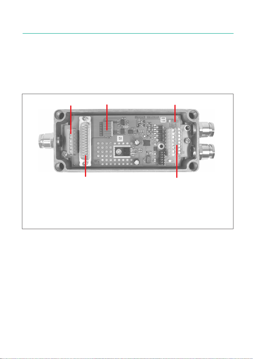
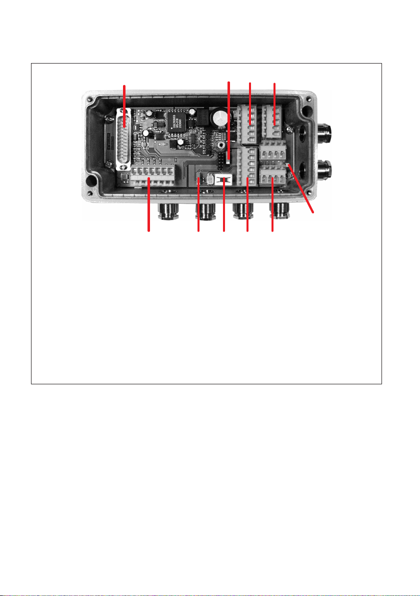
4.1 Mechanical construction of the AED9101D
1
1 Transducer connection
2 Interface setting (bus termination, type of interface)
3 RS‐485 bus termination
4 AD103C amplifier connection
5 Terminals for interface, supply voltage, trigger input and diagnostic bus
23
45
Fig. 4.1 Mechanical construction of the AED9101D
AED
MECHANICALCONSTRUCTION
12
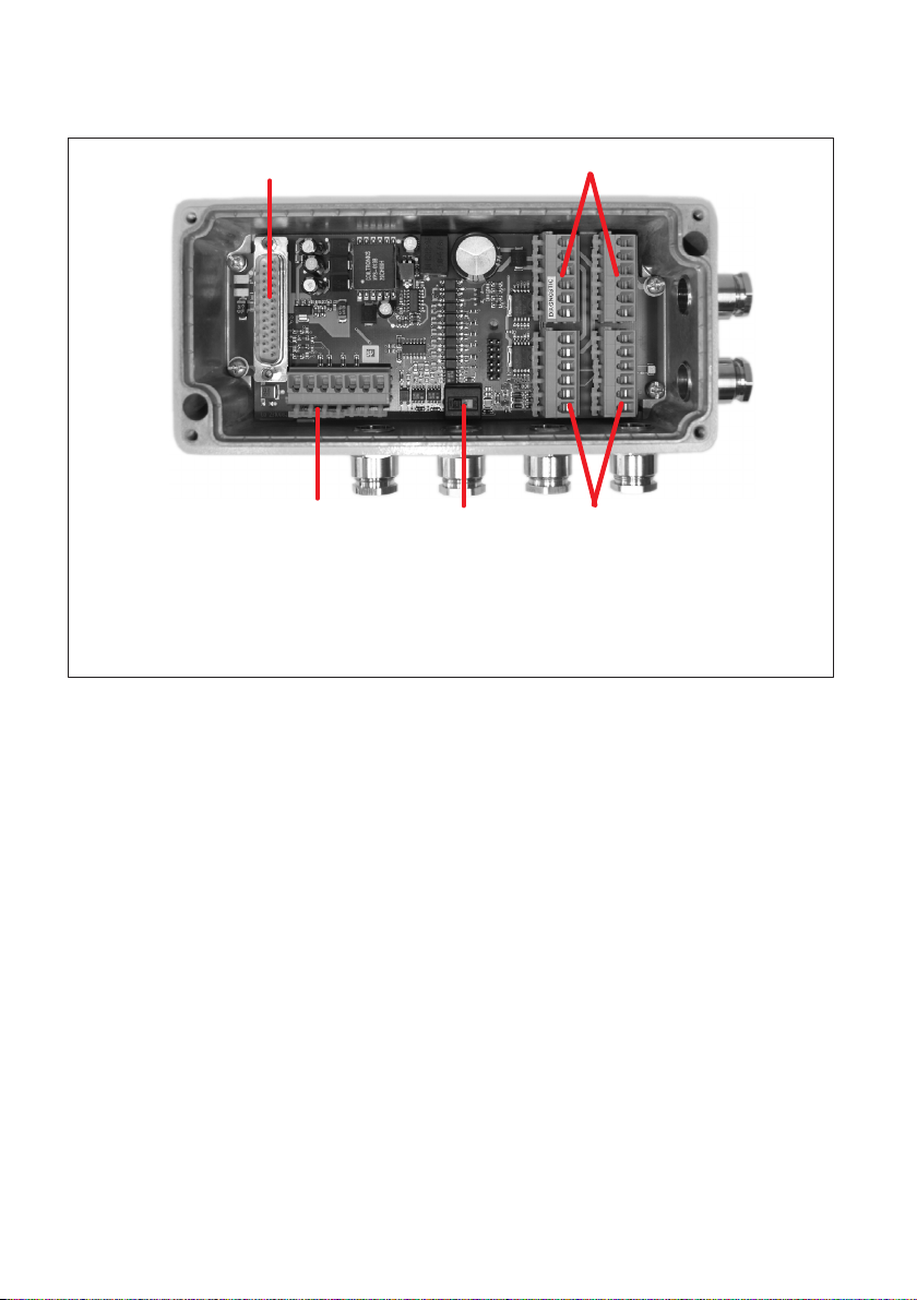
4.2 Mechanical construction of the AED9201B
12
45
3
1 Transducer connection
2 Interface setting (RS-232 or RS-485)
3 Power supply and interface connection (electrically isolated from AD103C)
4 AD103C amplifier connection
5 Digital I/O (electrically isolated from AD103C) and diagnostic bus
Fig. 4.2 Mechanical construction of the AED9201B

13
AED
MECHANICALCONSTRUCTION
4.3 Mechanical construction of the AED9301B
1
LED4
3
2
LED3
LED2
LED1
456
1 AD103C amplifier connection
2 Power supply and digital I/Os (electrically isolated from AD103C and PROFIBUS)
3 Transducer connection
4 Address interface setting
5 PROFIBUS connection (electrically isolated)
6 Diagnostic bus
7 Bus termination (PROFIBUS) and PROFIBUS disconnection (for diagnosis)
7
Fig. 4.3 Mechanical construction of the AED9301B
LED Function Explanation
LED1
(green)
PROFIBUS power sup
ply
The LED lights up to indicate that there is a
supply voltage to the interface driver.
LED2
(green)
PROFIBUS
data exchange
Shows the status of the cyclical data exchange.
LED3
(yellow)
PROFIBUS diagnosis The LED lights up if there is an internal error.
The measurement data may be invalid.
LED4 (red) PROFIBUS error The LED lights up if there is an bus error.
Possible causes:
- Incorrect wiring (A and B transposed?)
- PROFIBUS master not (yet) working
AED
MECHANICALCONSTRUCTION
14
4.4 Mechanical construction of the AED9401A
3
1 AD103C amplifier connection
2 CAN bus or DeviceNet bus selection
3 Power supply and digital outputs (electrically isolated from AD103C)
4 Digital inputs (electrically isolated from AD103C)
5 Transducer connection
6 Bus termination
7 Disconnection of AED from the bus system
8 Diagnostic bus
9 CAN bus and DeviceNet (electrically isolated from AD103C)
10 LED power supply
124
56789
10
Fig. 4.4 Mechanical construction of the AED9401A

15
AED
MECHANICALCONSTRUCTION
4.5 Mechanical construction of the AED9501A
1 Transducer connection
2 Bus termination
3 CANopen and DeviceNet interfaces (electrically isolated from AD103C)
4 AD103C amplifier connection
5 CANopen or DeviceNet bus selection
6 Power supply and trigger input connections
1 2 3
456
Fig. 4.5 Mechanical construction of the AED9501A

AED
MECHANICALINSTALLATION
16
5 MECHANICAL INSTALLATION
Conditions at the installation site
SProtect the device from direct contact with water.
SProtect the device from moisture and weather such as rain or snow. The protection
class of the device is IP65 (DIN EN 60529).
SDo not expose the device to direct sunlight.
Mounting position
The device can be mounted in any position.
Installation
Mount the device with two bolts with an outside diameter of less than 4.4mm. Remove
the cover of the housing to reach the mounting holes.
Please also see section 6.2 starting on page 19, which explains correct connection via
one of the PG glands.
After cable installation, tighten the screws of the housing cover to a torque of approx.
1Nm to ensure the stated IP rating and the best possible EMC protection.

17
AED
ELECTRICAL CONNECTION
6 ELECTRICAL CONNECTION
Notice
Electroniccomponents are sensitive to electrostatic discharge (ESD). You must therefore
discharge your own static electricity before opening the device. We recommend wearing
an antistatic band (conductive wristband) and using a conductive base.
The required power supply is an extra-low voltage (max. 30 VDC ) with protective separa
tion from the mains.
6.1 Ground (GND) and shield wiring
Use shielded cables for the connecting cables to the transducers and interfaces. Connect
the shield fully to both sides of the housing of the devices or to metal connectors or met
alized connector housings, not to the measurement ground, GND or the power supply
0V. An example of cable shield, supply voltage and transducer wiring is shown in Fig. 6.1
on page 18. Adouble shielded cable is advantageous for improved EMC.
In this case, the cables for the supply voltage and digital I/Os only need to be shielded if
they are longer than 30m or are routed outside closed buildings (as per EN 61326 1).
For connection, please ensure that the cable wires do not project beyond the connection
terminals (risk of short circuit) and do not lie on the amplifier board (risk of interference
coupling). The correct connection of the cable shield to the PG gland is described in sec
tion 6.2 on page 19.

AED
ELECTRICAL CONNECTION
18
Interface(s)
Power
supply
Digital I/O
AED
24V 0 V
Power
supply
Optional
PC/master/
slave
Transducer
Optional
Fig. 6.1 Example of shield connection
Tip
A connection diagram is attached with adhesive inside the cover of the basic device.
Notice
For cables 30m long or more, there is a risk that individual bus nodes will have different
ground potentials. In this case, establish a potential equalization between the bus nodes
using a separate cable.
For potential equalization, the best choice is a flexible cable with a minimum conductor
cross-section of 10mm2.
Other manuals for AED 9101D
1
This manual suits for next models
4
Table of contents
Languages:
Other HBK Transducer manuals


