HBK HBM Bruel & Kjaer U10M User manual

U10M, U10S
ENGLISH DEUTSCH FRANÇAIS ITALIANO
Mounting Instructions
Montageanleitung
Notice de montage
Istruzioni per il montaggio

Hottinger Brüel & Kjaer GmbH
Im Tiefen See 45
D-64293 Darmstadt
Tel. +49 6151 803-0
Fax +49 6151 803-9100
www.hbkworld.com
Mat.: 7-2001.1385
DVS: A01385 06 YIC 09
05.2022
EHottinger Brüel & Kjaer GmbH
Subject to modifications.
All product descriptions are for general information
only. They are not to be understood as a guarantee of
quality or durability.
Änderungen vorbehalten.
Alle Angaben beschreiben unsere Produkte in allge
meiner Form. Sie stellen keine Beschaffenheits- oder
Haltbarkeitsgarantie dar.
Sous réserve de modifications.
Les caractéristiques indiquées ne décrivent nos
produits que sous une forme générale. Elles
n'impliquent aucune garantie de qualité ou de
durabilité.
Con riserva di modifica.
Tutti i dati descrivono i nostri prodotti in forma
generica e non implicano alcuna garanzia di qualità o
di durata dei prodotti stessi.
保留变更的权利。
所有信息是对我品的性描。在性或者
性方它并提供何保。

U10M, U10S
ENGLISH DEUTSCH FRANÇAIS ITALIANO
Mounting Instructions

U10M, U10S
TABLE OF CONTENTS
2
TABLE OF CONTENTS
1 Safety instructions 4................................................
2 Markings used 7....................................................
2.1 The markings used in this document 7.................................
3 Scope of supply and Options 8.......................................
4 General application instructions 11....................................
5 Structure and mode of operation 12....................................
5.1 Transducer 12.......................................................
5.2 SG covering agent 12.................................................
6 Conditions on site 13.................................................
6.1 Ambient temperature 13..............................................
6.2 Moisture and corrosion protection 13...................................
6.3 Deposits 13.........................................................
7 Mechanical installation 15............................................
7.1 Important precautions during installation 15..............................
7.2 General installation guidelines 15.......................................
7.3 Assembly with adapter 16.............................................
7.4 Mounting with PLS ramp disks 20......................................
7.5 Mounting with knuckle eyes 22.........................................
7.6 Assembly without adapter 27..........................................
7.7 Mounting with a fitted force application part 29...........................
8 Electrical connection 30..............................................
8.1 Connection in a six-wire configuration 30................................
8.2 Cable shortening or extension 31.......................................
8.3 Connection in a four-wire configuration 31...............................
8.4 EMC protection 31...................................................
9 TEDS transducer identification 32......................................
10 Versions and ordering numbers 33.....................................
11 Specifications (VDI/VDE2638) 36......................................
12 Dimensions 48......................................................
12.1 U10M with foot adapter 48............................................
12.2 U10M without foot adapter 50.........................................

3
U10M, U10S
TABLE OF CONTENTS
12.3 U10M with force application and foot adapter 51.........................
12.4 U10M with knuckle eyes 52............................................
12.5 PLS ramp disk dimensions 53..........................................
12.6 Installed dimensions of connection variants 54...........................

U10M, U10S
SAFETY INSTRUCTIONS
4
1 SAFETY INSTRUCTIONS
Intended use
The force transducers of the U10M/U10S type series are solely designed for measuring
static and dynamic tensile and/or compressive forces within the load limits stated in the
specifications for the respective maximum capacities. Any other use is not appropriate.
To ensure safe operation, the regulations in the mounting instructions, together with the
following safety rules and regulations, and the data specified in the technical data sheets,
must be complied with. It is also essential to observe the applicable legal and safety reg
ulations for the application concerned.
The force transducers are not intended for use as safety components. Please also refer
to the "Additional safety precautions" section. Proper and safe operation of force trans
ducers requires proper transportation, correct storage, setup and mounting, and careful
operation.
Load-carrying capacity limits
The information in the technical data sheets must be complied with when using force
transducers. The respective specified maximum loads in particular must never be
exceeded. The following limits set out in the technical data sheets must not be exceeded:
SForce limits
SLateral force limits
SBending moment limits
STorque limits
SBreaking forces
SPermissible dynamic loads
STemperature limits
SLimits of electrical loading capacity
Please note that when several force transducers are interconnected, the load/force
distribution is not always uniform.
Use as a machine element
Force transducers can be used as machine elements. When used in this manner, it must
be noted that, to favor greater sensitivity, the force transducers were not designed with
the safety factors usual in mechanical engineering. Please refer here to the section
"Load-carrying capacity limits", and to the specifications.

5
U10M, U10S
SAFETY INSTRUCTIONS
Accident prevention
The prevailing accident prevention regulations must be taken into account, even though
the nominal (rated) force values in the destructive range are well in excess of the full
scale value.
Additional safety precautions
Force transducers cannot (as passive transducers) implement any safety-relevant cut
offs. This requires additional components and constructive measures, for which the in
staller and operator of the plant is responsible.
In cases where a breakage or malfunction of the force transducer would cause injury to
persons or damage to equipment, the user must take appropriate additional safety mea
sures that meet at least the requirements of applicable safety and accident prevention
regulations (e.g. automatic emergency shutdown, overload protection, catch straps or
chains, or other fall protection).
The electronics conditioning the measurement signal should be designed so that mea
surement signal failure does not subsequently cause damage.
General dangers of failing to follow the safety instructions
Force transducers are state-of-the-art and failsafe. There may be dangers involved if the
transducers are mounted, sited, installed and operated inappropriately, or by untrained
personnel. Every person involved with siting, starting-up, operating or repairing a force
transducer must have read and understood the mounting instructions and in particular
the technical safety instructions. The force transducers can be damaged or destroyed by
non-designated use of the force transducer or by non-compliance with the mounting and
operating instructions, these safety instructions or any other applicable safety regula
tions (BG safety and accident prevention regulations) when using the force transducers.
Force transducers can break, particularly if overloaded. The breakage of a force trans
ducer can also cause damage to property or injury to persons in the vicinity of the force
transducer.
If force transducers are not used according to their designated use, or if the safety in
structions or specifications in the mounting and operating instructions are ignored, it is
also possible that the force transducer may fail or malfunction, with the result that per
sons or property may be affected (due to the loads acting on or being monitored by the
force transducer).
The scope of supply and performance of the transducer covers only a small area of force
measurement technology, as measurements with (resistive) strain gage sensors presup
pose the use of electronic signal processing. In addition, equipment planners, installers
and operators should plan, implement and respond to the safety
engineering considerations of force measurement technology in such a way as to mini
mize residual dangers. Pertinent national and local regulations must be complied with.

U10M, U10S
SAFETY INSTRUCTIONS
6
Conversions and modifications
The design or safety engineering of the transducer must not be modified without our ex
press permission. Any modification shall exclude all liability on our part for any damage
resulting therefrom.
Maintenance
U10M/U10S force transducers are maintenance-free. We recommend having the force
transducer calibrated at regular intervals.
Disposal
In accordance with national and local environmental protection, material recovery and
recycling regulations, old transducers that can no longer be used must be disposed of
separately and not with normal household waste.
If you need more information about disposal, please
contact your local authorities or the dealer from whom you purchased the product.
Qualified personnel
Qualified personnel are persons entrusted with the setup, mounting, startup and opera
tion of the product, who have the appropriate qualifications for their function.
This includes people who meet at least one of the three following requirements:
1. Knowledge of the safety concepts of automation technology is a requirement and as
project personnel, you must be familiar with these concepts.
2. As automation plant operating personnel, you have been instructed how to handle the
machinery. You are familiar with the operation of the equipment and technologies
described in this documentation.
3. As commissioning engineers or service engineers, you have successfully completed
the training to repair the automation systems. You are also authorized to operate,
ground and label circuits and equipment in accordance with safety engineering stan
dards.
It is also essential to comply with the legal and safety requirements for the application
concerned during use. The same also applies to the use of accessories.
The force transducer may only be installed by qualified personnel, strictly in accordance
with the specifications and with the safety requirements and regulations.
7
U10M, U10S
MARKINGS USED
2 MARKINGS USED
2.1 The markings used in this document
Important instructions for your safety are specifically identified. It is essential to follow
these instructions in order to prevent accidents and damage to property.
Symbol Significance
WARNING This marking warns of a potentially dangerous situ
ation in which failure to comply with safety require
ments can result in death or serious physical injury.
CAUTION This marking warns of a potentially dangerous
situation in which failure to comply with safety
requirements can result in slight or moderate physical
injury.
NOTICE This marking draws your attention to a situation in
which failure to comply with safety requirements can
lead to damage to property.
Important This marking draws your attention to important in
formation about the product or about handling the
product.
Tip This marking indicates application tips or other
information that is useful to you.
Information This marking draws your attention to information
about the product or about handling the product.
Emphasis
See …
Italics are used to emphasize and highlight text and
identify references to sections, diagrams, or external
documents and files.
uThis marking indicates an action in a procedure

U10M, U10S
SCOPE OF SUPPLY AND OPTIONS
8
3 SCOPE OF SUPPLY AND OPTIONS
SForce transducer U10M (metric internal thread) or
U10S (UNF internal thread)
SU10M/U10S mounting instructions
SManufacturing certificate
SMachine handles for handling use on variants 225kN to 500kN
Accessories (not included in the scope of supply):
Cables/plugs Ordering number
Configurable cable, including mounted connectors for direct
connection to HBM amplifiers available upon request. K-CAB-F
Connection cable KAB157-3; IP67 (with bayonet locking);
3m long, TPE outer sheath; 6 x 0.25mm2; free ends,
shielded, outside diameter 6.5mm
1-KAB157-3
Connection cable KAB158-3; IP54 (with screw locking); 3m
long, TPE outer sheath; 6 x 0.25mm2; free ends, shielded,
outside diameter 6.5mm
1-KAB158-3
Loose cable socket (bayonet locking) 3-3312.0382
Loose cable socket (screw locking) 3-3312.0354
Ground cable (400mm long) 1-EEK4
Ground cable (600mm long) 1-EEK6
Ground cable (800mm long) 1-EEK8
Knuckle eye, M16 external thread 1-Z4/20kN/ZGUW
Knuckle eye, M33x2 external thread 1-ZGAM33F
Knuckle eye, M42x2 external thread 1-ZGAM42F
Knuckle eye, M72x2 external thread 1-ZGAM72F
Knuckle eye, M16 internal thread 1-Z4/20kN/ZGOW
Knuckle eye, M33x2 internal thread 1-ZGIM33F
Knuckle eye, M42x2 internal thread 1-ZGIM42F
Knuckle eye, M72x2 internal thread 1-ZGIM72F
Ramp disk (pre-stress disk), M16 1-PLS/M16
Ramp disk (pre-stress disk), M33 1-PLS/M33
Ramp disk (pre-stress disk), M42 1-PLS/M42

9
U10M, U10S
SCOPE OF SUPPLY AND OPTIONS
Ordering numberCables/plugs
Ramp disk (pre-stress disk), M72 1-PLS/M72
Ramp disk (pre-stress disk), M120 1-PLS/M120
Equipment variants
All force transducers are available in different versions. The following options are avail
able:
1. Nominal (rated) force:
You can purchase nominal (rated) forces from 1.2 5kN to 1.2 5MN.
2. Double bridge design
The force transducer is also available with two electrically isolated measurement
bridge circuits.
3. Adjusted rated output
On request, we can adjust the rated output of your U10M to exactly match the nominal
rated output. In sensors with nominal (rated) forces 1.25kN, 2.5kN and 5kN, the out
put signal at nominal (rated) force is then 1mV/V, in all other force transducers it is
2mV/V. These values apply together with 100% calibration (standard). If you choose
the 200% calibration option, the output signal doubles. If you order the "adjusted rated
output" option, the output resistance is always adjusted as well, so that several sen
sors can be connected in parallel. (Exception: nominal (rated) force 1.25MN is not
suitable for parallel connection)
4. Calibration
On request, HBM can calibrate the force transducer to 200% nominal (rated) force.
The high mechanical reserves of the force transducer make this application possible
in measurement tasks with a limited oscillation bandwidth (see Specifications). But be
aware that when double the force is measured, the output signal also doubles.
5. TEDS transducer identification
You can purchase the force transducer with transducer identification ("TEDS"). TEDS
(Transducer Electronic Data Sheet) allows you to store the transducer data (rated out
puts) in a chip, that can be read out by a connected measuring device. Each measur
ing bridge has a separate TEDS in the double bridge variant. See also Page 32.
6. Without adapter
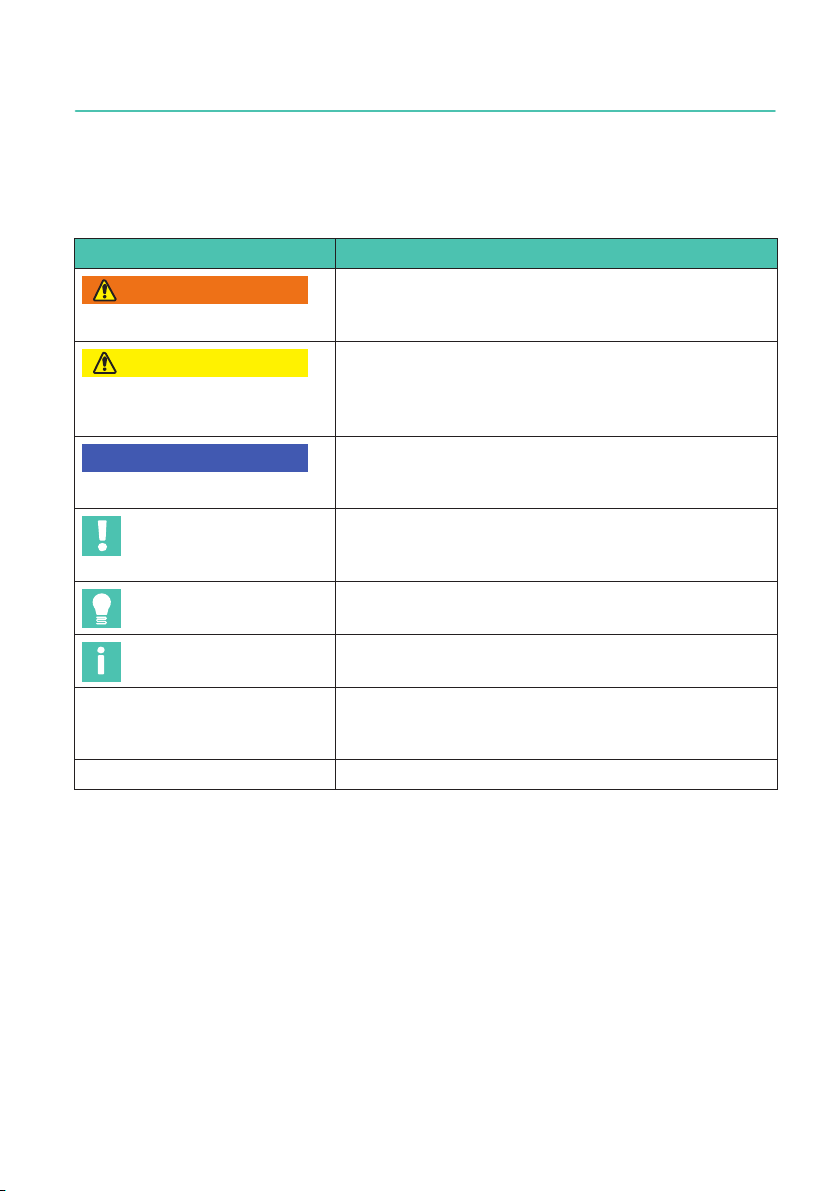
You can purchase the force transducer without an adapter. The force transducer can
then be directly screwed onto a structural element using the pitch circle, see Fig. 3.1.
U10M, U10S
SCOPE OF SUPPLY AND OPTIONS
10
Fig. 3.1 U10M with adapter (left) and without adapter (right)
7. Plug protection
On request, we can fit plug protection, consisting of a rectangular tube (round tube for
nominal (rated) force 1.25MN), so that the plug is protected against
mechanical damage
8. Threaded connector or fixed cable
The standard version of the force transducer is
delivered with a bayonet connector. On request, a threaded connector or fixed cable
6m or 15m long can be provided instead.
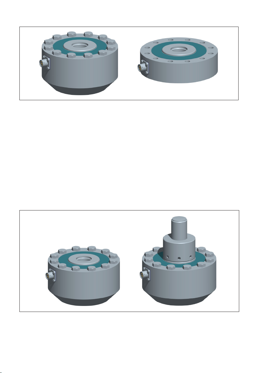
9. Force application part
On request, we can deliver the U10M with a force
application part mounted in the central thread, see Fig. 3.2 on Page 10.
Fig. 3.2 U10M without force application bolt (left) and with mounted force application
bolt (right); both pictures with foot adapter

11
U10M, U10S
GENERAL APPLICATION INSTRUCTIONS
4 GENERAL APPLICATION INSTRUCTIONS
The force transducers are suitable for measuring tensile and compressive forces. They
provide highly accurate static and dynamic force measurements and must therefore be
handled very carefully. Particular care must be taken when transporting and installing the
devices. Dropping or knocking the transducer may cause permanent damage.
U10M force transducers have a metric internal thread and U10S force transducers have
an internal thread to UNF standard.
The permissible limits for mechanical, electrical and thermal stress are listed in the Chap
ter "" on page 36. It is essential to take these limits into account when planning the mea
suring set-up, during installation and, ultimately, during operation.

U10M, U10S
STRUCTURE AND MODE OF OPERATION
12
5 STRUCTURE AND MODE OF OPERATION
5.1 Transducer
The measuring element is a loaded member made of steel (for nominal (rated) forces
from 12.5kN) or high-strength aluminum (for nominal (rated) forces up to 5kN), to which
strain gages (SG) are applied. The SG are arranged in each measuring circuit so that four
are extended and the other four shortened when a force acts on the transducer. Each
strain gage changes its ohmic resistance in proportion to its change in length and so mis
aligns the Wheatstone bridge. If bridge excitation voltage is present, the circuit produces
an output signal proportional to the change in resistance and thus also proportional to the
applied force. The arrangement of the SGs is selected so that parasitic forces or torques
and temperature effects are compensated as much as possible.
5.2 SG covering agent
To protect the SG, the force transducers have thin cover plates that are welded (steel
versions) or glued (aluminum versions) top and bottom. This procedure offers the SG a
high level of protection against environmental influences. In order to retain the protective
effect, these plates must not be damaged in any way.

13
U10M, U10S
CONDITIONS ON SITE
6 CONDITIONS ON SITE
Protect the transducer from weather conditions such as rain, snow, ice, and salt water.
6.1 Ambient temperature
The temperature effects on the zero signal and on the rated output are compensated.
To obtain optimum measurement results, the nominal (rated) temperature range must be
complied with. The arrangement of the SG results in extreme insensitivity to temperature
gradients, due to its construction. Nevertheless, constant or very slowly changing temper
atures are best. A radiation shield and all-round thermal insulation produce noticeable
improvements, but must not be allowed to set up a force shunt.
6.2 Moisture and corrosion protection
The force transducers are hermetically encapsulated and are therefore very insensitive to
moisture.
The protection class of the sensors depends on the choice of electrical connection. In the
standard version with a bayonet connector, the sensor achieves degree of protection
IP 67 as per DIN EN60259 (test conditions: 0.5 hours under a 1-meter water column).
This applies when the plug is connected.
Optionally, the force transducers are also available fitted with a fixed cable. In this ver
sion, all U10 achieve degree of protection IP68 with a nominal (rated) force equal to or
greater than 12.5kN. In the threaded connector version, the sensors achieve degree of
protection IP64.
The transducer must be protected against chemicals that could attack the steel (nominal
(rated) forces from 12.5kN) or aluminum (nominal (rated) forces up to 5kN).
With stainless steel force transducers, note that acids and all materials which release
ions will also attack stainless steels and their seam welds. Any resulting corrosion could
cause the force transducer to fail. In this case, appropriate protective measures must be
implemented.
We recommend protecting the transducer against long-term exposure to moisture and
weather conditions.
6.3 Deposits
Dust, dirt and other foreign matter must not be allowed to accumulate sufficiently to di
vert some of the measuring force onto the housing, thus distorting the measured value
(force shunt). The relevant areas are marked in Fig. 6.1.

U10M, U10S
CONDITIONS ON SITE
14
The gap must remain free
Fig. 6.1 Deposits must not be allowed to form where marked.

15
U10M, U10S
MECHANICAL INSTALLATION
7 MECHANICAL INSTALLATION
7.1 Important precautions during installation
SHandle the transducer with care.
SComply with the requirements for the force application parts as specified in Sec
tion 7.3 and Section 7.6.
SWelding currents must not be allowed to flow over the transducer. If there is a risk
that this might happen, you must provide a suitable low-ohm connection to electrically
bypass the transducer. HBM provides the highly flexible EEK ground cable for this
purpose, for example. It can be screwed on above and below the transducer.
SMake sure that the transducer cannot be overloaded.
WARNING
There is a danger of the transducer breaking if it is overloaded. This can cause danger for
the operating personnel of the system in which the transducer is installed.
Implement appropriate safety measures to avoid overloads (see Specifications in
Chapter 11, page 36) or to protect against resulting dangers.
7.2 General installation guidelines
The forces to be measured must act on the transducer as accurately as possible in the
direction of measurement. Torques and bending moments, eccentric loading and lateral
forces may produce measurement errors and destroy the transducer, if limit values are
exceeded.
U10M, U10S
MECHANICAL INSTALLATION
16
de
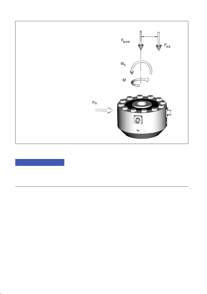
Fnom: Force in direction of measurement
Fex: Force parallel to direction of measurement, but
outside center of force transducer
FQ: Force vertical to direction of measurement
Mb: Bending moment
Md: Torque
d
Fig. 7.1 Parasitic forces and moments
Notice
When installing and operating the transducers, please note the maximum parasitic forces -
lateral forces, bending and torsional moments, see Chapter 11, page 36 - and the maximum
permissible load-carrying capacity of the force application parts used.
7.3 Assembly with adapter
The U10 can be directly mounted onto the structural
elements in this mounting variant. The internal threads on the force transducer and
adapter can be used for this purpose. The transducer can then measure axial forces in
both the tensile and pressure directions. Alternating loads are also correctly recorded if the
transducer is mounted without axial play. The transducer can be used without restrictions
with the full oscillation bandwidth.
The customer's own structural elements (threaded bolts) must meet the following condi
tions:
SThe upper and lower force application parts must be aligned as accurately as possible
in one axis. Installation is facilitated by centering aids at top and bottom. The center

17
U10M, U10S
MECHANICAL INSTALLATION
ing diameter corresponds to dimension P, the admissible centering depth is 3mm
(see Page 48ff).
SThe anti-screw-through device attached to the internal thread of the adapter must not
be removed.
SThe (customer-side) external thread must comply with a thread tolerance of 6g for
metric threads and 3A for UN/UNF threads.
SThe threads must be cleaned of any deposits and soaked with graphite-free grease
before being screwed in.
SThe following applies for steel force transducers (nominal (rated) forces from
12.5kN): To achieve the full endurance strength, a material with sufficient
tensile strength (min. Rp,0.2 = 900 N/mm2) and hardness (min. 40HRC) must be used.
We recommend the use of threads rolled after heat treatment for measurement
ranges between 225kN and 500kN.
If the customer fits their own force application parts in the U10, and these have a differ
ent coefficient of thermal expansion from that of the measuring bodies (e.g. a steel
thread in an aluminum measuring body), and if these are fitted tilted or uncentered, ther
mal stress may be produced during temperature variations that may adversely affect the
temperature dependence of the zero point due to irregular deformation. In this case, to
ensure precise measurements we recommend centering using centering dimension “P”,
and using a nut that ensures a right angle for locking (e.g. by grinding the nut).
Alternatively, the connecting part could be designed so that it is fitted without locking
using centering dimension P. This is possible whenever the connecting structural ele
ments can be mounted using the "Pre-stressing with defined tightening torque" method
(see table Tab. 7.1, page 19). This is the case for all nominal (rated) forces up to and
including 25 kN.

U10M, U10S
MECHANICAL INSTALLATION
18
A
0,03 A
0,02
16,5 f7
76
23
22,1
25
39
SR60
M16
22
11
M16 M16
A
16,5 f7
11
1x45°
min. 22
2:1
A
Fig. 7.2 Adapter dimensions
You do not need to pay attention to this information if measurement takes place at uni
form temperatures or taring is possible before changes in temperature. Likewise, large
nominal (rated) forces above 25 kN are not affected.
The screwed-in force application parts must be sufficiently pre-stressed to meet the
stated specifications and the full endurance strength of the threads. This is implemented
with a locknut screwed onto the customer-side structural element. We recommend using
one of the methods described below.
1. Pre-stressing with defined tightening torque
Force transducers with a nominal force up to and including 25kN can be mounted
using this method.
SScrew the force application part into the transducer or adapter as far as the retainer.
SUnscrew force application part two revolutions.
SPre-stress force application part with defined tightening torque.
Nominal (rated) force Tightening torque MAThread reach
in kN in N@min lb@inch in mm in inch
1.25 17 150 26.4 1.04
2.5 35 310 26.4 1.04
5 68 600 26.4 1.04
This manual suits for next models
1
Table of contents
Languages:
Other HBK Transducer manuals


Popular Transducer manuals by other brands


Woodward
Woodward UMT 1 manual

Philips
Philips Avalon CTS M2720A Service guide

Veris
Veris Hawkeye H421SP installation guide

NK TECHNOLOGIES
NK TECHNOLOGIES AT-TH Series instructions

S+S Regeltechnik
S+S Regeltechnik AERASGARD RCO2-W-A Operating Instructions, Mounting & Installation

Carrier
Carrier 48NP installation instructions