HBM ML71BS6 User manual

A0851-3.1 en
MGCplus Measuring
amplifier system
CAN bus interface
ML71BS6
Operating manual


3
MGCplus−ML71BS6
A0851-3.1 de HBM
Contents Page
Safety instructions 4. . . . . . . . . . . . . . . . . . . . . . . . . . . . . . . . . . . . . . . . . . . . . . .
1 Introduction 6. . . . . . . . . . . . . . . . . . . . . . . . . . . . . . . . . . . . . . . . . . . . . . . . .
2 Connections 7. . . . . . . . . . . . . . . . . . . . . . . . . . . . . . . . . . . . . . . . . . . . . . . . .
2.1 Pin assignment 7. . . . . . . . . . . . . . . . . . . . . . . . . . . . . . . . . . . . . . . . . .
3 Front panel 8. . . . . . . . . . . . . . . . . . . . . . . . . . . . . . . . . . . . . . . . . . . . . . . . . .
4 Parameterization 9. . . . . . . . . . . . . . . . . . . . . . . . . . . . . . . . . . . . . . . . . . . . .
4.1 Settings CAN1 /CAN2 9. . . . . . . . . . . . . . . . . . . . . . . . . . . . . . . . . . . .
4.1.1 Panel output signals CAN 1 11. . . . . . . . . . . . . . . . . . . . . .
5 Menu structure in set-up mode 13. . . . . . . . . . . . . . . . . . . . . . . . . . . . . . .
6 CAN protocol 14. . . . . . . . . . . . . . . . . . . . . . . . . . . . . . . . . . . . . . . . . . . . . . .
6.1 Measurement signal transmission 14. . . . . . . . . . . . . . . . . . . . . . . . .
6.1.1 Absolute values in Float 14. . . . . . . . . . . . . . . . . . . . . . . . .
6.1.2 In digits as Long 14. . . . . . . . . . . . . . . . . . . . . . . . . . . . . . . .
6.1.3 In digits as Word 14. . . . . . . . . . . . . . . . . . . . . . . . . . . . . . . .
6.1.4 Identifier assignment 14. . . . . . . . . . . . . . . . . . . . . . . . . . . .
7 Specifications 16. . . . . . . . . . . . . . . . . . . . . . . . . . . . . . . . . . . . . . . . . . . . . .

4
MGCplus−ML71BS
6
A0851-3.1 enHBM
Safety instructions
Use in accordance with the regulations
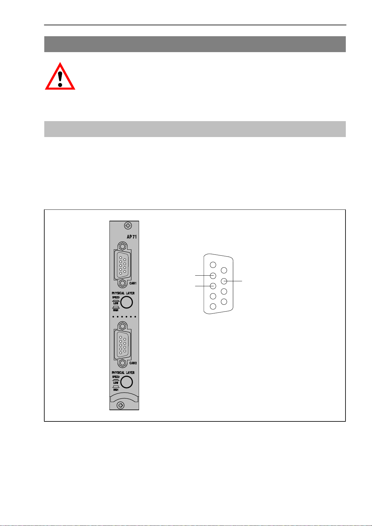
The ML71BS6 CAN bus module is to be used exclusively for measurement
tasks and directly related control tasks. Use for any purpose other than the
above shall be deemed to be not in accordance with the regulations.
To ensure safe operation, the device may only be operated in accordance with
the information given in the Operating Manual. It is also essential to comply
with the legal and safety requirements for the application concerned during
use. The same applies to the use of accessories.
General dangers of failing to follow the safety instructions
The ML71BS6 CAN bus module complies with the state of the art and is
fail-safe. The device may give rise to further dangers if it is inappropriately
installed and operated by untrained personnel.
Any person instructed to carry out installation, commissioning, maintenance or
repair of the device must have read and understood the Operating Manual
and in particular the technical safety instructions.
Remaining dangers
The scope of performance and supply of the ML71BS6 only covers part of the
range of measurement technology. In addition, equipment planners, installers
and operators should plan, implement and respond to the safety engineering
considerations of measurement technique in such a way as to minimise
remaining dangers. Prevailing regulations must be complied with at all times.
There must be reference to the remaining dangers connected with
measurement technique.
In this manual, the following symbols are used to draw your attention to any
remaining dangers that might occur when working with the ML71BS6:
Symbol: WARNING
Meaning: Dangerous situation
Warns of a potentially dangerous situation in which failure to comply with
safety requirements can lead to death or serious physical injury.

5
MGCplus−ML71BS6
A0851-3.1 en HBM
Symbol:
Meaning: CE mark
The CE mark enables the manufacturer to guarantee that the product com-
plies with the requirements of the relevant EC directives (the declaration of
conformity is available at http://www.hbm.com/HBMdoc).
Working safely
Error messages must only be acknowledged when the cause of the error has
been removed and no further danger exists.
The device complies with the safety requirements of DIN EN 61010-Part 1
(VDE 0411-Part 1); Protection Class I.
To ensure adequate immunity from interference, use only Greenline shielded
ducting (see HBM offprint ”Greenline shielding design, EMC-compliant mea-
suring cable; G36.35.0)
Conversions and modifications
No modifications that affect the design or the technical safety of the ML71BS6
CAN bus module may be carried out without our express agreement. Any
modification shall exclude all liability on our part for any resulting damage.
In particular any repair or soldering work on motherboards is prohibited. When
exchanging complete modules, use only original parts from HBM.
Qualified personnel
This instrument must only to be installed and used by qualified personnel,
strictly in accordance with the technical data and the safety requirements and
regulations listed. It is also essential to comply with the legal and safety
requirements for the application concerned during use. The same applies to
the use of accessories.
Qualified personnel means persons entrusted with the installation, assembly,
commissioning and operation of the product who possess the appropriate
qualifications for their function.
Maintenance and repair work on an open device with the power on must only
be carried out by trained personnel who are aware of the danger involved.

6
MGCplus−ML71BS
6
A0851-3.1 enHBM
1 Introduction
The ML71BS6 is an MGCplus system module that takes measurement data
from the MGC and outputs it as CAN messages. It records up to 128
measured values per CAN port, scales them and outputs them at the CAN
bus.
Two independent CAN interfaces per channel and two different physical layers
(ISO 11898−24V and a ”low-speed” link based on the Philips TJA1053
transceiver module) are supported.
The measurement data to be transmitted can be selected either by using the
AB22A/AB32 display and control panel or by using the “MGCplus Assistant”
software from HBM.

7
MGCplus−ML71BS6
A0851-3.1 en HBM
2 Connections
WARNING
Before starting the device, read the safety instructions.
2.1 Pin assignment
The CAN bus is connected to the AP71 connection board by a 9-pin Sub-D
connector. You can connect two independent CAN field bus systems (female
connectors CAN1 and CAN2). Both the CAN interfaces are used to output the
MGCplus measurement data. Each of the interfaces can be assigned up to
128 measured values.
Connectors (male)
CAN1/CAN2
1
5
6
9
CAN Shield
CAN_GND
CAN_L CAN_H
GND
CAN_V+
Physical layer:
High: Standard CAN speeds up to 1MBaud acc. to ISO11898
(24 V dielectric strength).
Low: Low−speed bus for in-car communication up to 100 kBaud
(CAN_V+ must be connected to 12 V)
Fig. 2.1: CAN connection

ML71
BS6
8
MGCplus−ML71BS
6
A0851-3.1 enHBM
3 Front panel
The front panel LEDs have a dual function:
In Level mode, the signal level at the analogue output is displayed.
In Status mode, the LEDs are assigned as shown below:
LED caption Colour Meaning in Status mode
CHAN. yellow Channel selected
ERROR/WARN. red error/warning
Rx1 − not used
Tx1/OVRN1 red/yel-
low CAN protocol transmitted
BUSERR1 red Bus error at CAN1
Rx2 yellow not used
Tx2/OVRN2 red/yel-
low CAN protocol transmitted
BUSERR2 red Bus error at CAN2
Analog output (BNC connector (female))
Any voltage from −10 V to +10 V can be output through the
female BNC connector by interface command.

9
MGCplus−ML71BS6
A0851-3.1 en HBM
4 Parameterization
4.1 Settings CAN1 /CAN2
The baud rate, the transmission formats, the number of signals and the output
rate of the 1st CAN bus are set here. The same menu is applied
correspondingly to the 2nd CAN bus.
The maximum number of signals for a bus is 128 signals.
The following output rates are offered for selection depending on the number
of output signals. In the case of the 2nd CAN port, please note that the
maximum possible output rates can only be achieved if no signals have been
selected at CAN port1.
If a selected rate cannot be achieved, the messages will be output as quickly
as possible and an error message will be generated. Transmission will then
not be at a fixed frequency.
Number of signals
Format
Output rate [Hz]
CAN1 CAN2
Format
Port1 Port2
4 4 INT16 2400 800
4 4 INT32 2400 600
4 4 Float32 2400 400
8 8 INT16 1200 800
8 8 INT32 1200 400
8 8 Float32 1200 300
16 16 INT16 600 600
16 16 INT32 600 300
16 16 Float32 600 300
The first ID of a range can be set. The last ID is derived from this and from the
number of signals.

10
MGCplus−ML71BS
6
A0851-3.1 enHBM
1 Use the shift key to change to set-up mode and then press the
function key . Use the cursor keys to select “Settings CAN1” and
confirm with .
Settings CAN1 CHANNEL3
1000 kBaud
System Display Parameters Options
Float
8
1200 1/2
Baud rate
Format
Number of signals
Output rate
ID range used
1000 kBaud
500 kBaud
.
.
10 kBaud
Float
32−bit integers
16−bit integers
1 1/s
10 1/s
.
.
1200 1/s
First ID
Last ID
Reset CAN1 port
640
641
Fig. 4.1: CAN1 / CAN2 dialogue window
2 Use the cursor keys to choose the baud rate selection field. Use to
call the selection list and choose the desired baud rate. Confirm with .
3 Select the output rate in the same way as for 2.
4 Use the cursor keys to select the “Number of signals” edit field and
enter the desired figure.
5 Select the output rate in the same way as for 2.
6 Use the cursor keys to select the “First ID” edit field and enter the
desired figure. The “Last ID” edit field is set automatically.
7 Use the shift key to change to measuring mode and confirm the
follow-up question with .

11
MGCplus−ML71BS6
A0851-3.1 en HBM
4.1.1 Panel output signals CAN 1
This is where to set the sources for the signals to be transmitted and if
necessary, scaling for the output values.
1 Use the shift key to change to set−up mode and then press the
function key . Use the cursor keys to select “Sources CAN1” and
confirm with .
Format 1; Absolute values Float
Sources CAN1 CHANNEL 3
CAN signal 1
System Display Parameters Options
Gross
Source for
MGC channel
Signal
CAN signal 1
CAN signal 2
.
.
CAN signal n
Gross
Net
Store1
Store2
Combined PV
8
Fig. 4.2: CAN1 / CAN 2 output signals dialogue window
2 Use the cursor keys to select the “Source for MGC channel” selection
field. Use to call the selection list and choose the desired CAN signal.
Confirm with .
3 Use the cursor keys to select the MGC channel field and enter the
desired channel (e.g. 8.1).
4 Use the cursor keys to select the “Signal” edit field. Use to call the
selection list and choose the desired signal. Confirm with .

12
MGCplus−ML71BS
6
A0851-3.1 enHBM
Formats 2 and 3; 32-bit integers and 16-bit integers
You must also specify scaling here.
1 Use the shift key to change to set−up mode and then press the
function key . Use the cursor keys to select “Sources CAN1” and
confirm with .
Sources CAN1 CHANNEL 3
CAN signal 1
System Display Parameters Options
Gross
0
Source for
MGC channel
Signal
Scaling
Point 1
CAN signal 1
CAN signal 2
.
.
CAN signal n
Gross
Net
Store1
Store2
Combined PV
Point 2
dig
10
7680000 dig
1000
8
kN
kN
Channel 8 to
128
Fig. 4.3: CAN1 / CAN 2 output signals dialogue window
2 Use the cursor keys to select the “Source for MGC channel” selection
field. Use to call the selection list and choose the desired signal.
Confirm with .
3 Use the cursor keys to select the MGC channel field and enter the
desired channel (e.g. 8.1).
4 Use the cursor keys to select the “Signal” edit field. Use to call the
selection list and choose the desired signal. Confirm with .
5 Use the cursor keys to select the “Point 1” edit field and enter the digit
value.
6 Use the cursor keys to select the next edit field and enter the value of
the accompanying physical unit.
7 Use the cursor keys to select the “Point 2” edit field and proceed in the
same way as for points 5 and 6.
8 Use the shift key to change to measuring mode and confirm the
follow-up question with .

13
MGCplus−ML71BS6
A0851-3.1 en HBM
5 Menu structure in set-up mode
The set−ups for the MGCplus unit are subdivided into groups according to
their function. Pressing the shift key takes you to the set-up dialogue, and
the selection bar is displayed.
System−specific set-
tings that in most ca-
ses are only carried
out during the initial
start-up or for a new
measurement task.
User−defiened dis-
play settings such as
the required method
of representing va-
lues, function key as-
signment or the spe-
cification of channel
names.
Output signal CAN1
Output signal CAN2 Settings CAN1
Settings CAN2
Version
Display in Setup mode Setup for channel 3
Display Parameters OptionsSystem
Setup
menu
DisplaySystem Parameters Options
You will find more notes on working with the AB22A display and control panel
in the “MGCplus with AB22A/AB32” manual.

14
MGCplus−ML71BS
6
A0851-3.1 enHBM
6 CAN protocol
Up to 128 measured values can be transmitted at each bus.
A number of signals is assigned to each bus. This determines the signal
transmission rate at the particular CAN port (in the case of CAN port 2, the
operating mode of CAN port 1 is also a factor).
6.1 Measurement signal transmission
The operating priority for the two CAN ports is different. CAN port 1 always
takes priority, to ensure that the transmission pattern of the data sent from
here is exactly periodic. When sending a synch signal, the values sent thus
far are valid here. CAN port 2 has the lower priority. Measurement signals can
be transmitted in the following three formats.
6.1.1 Absolute values in Float
In each 8−byte CAN message, 2 signals are transmitted as Float values
(32−bit). This is dealing with scaled measured values.
6.1.2 In digits as Long
In each CAN message, 2 of these values are transmitted as Long (32-bit),
with the MSByte1) always being 0. Digital value scaling can be preset by using
two point calibrations.
6.1.3 In digits as Word
In each CAN message, 4 of these values are transmitted as Words (16-bit).
Digital value scaling can be preset by using two point calibrations.
6.1.4 Identifier assignment
Default assignment
The possible formats are sent out for the same signal under different
identifiers, so that fixed scaling can be assigned in the receiver of a specific
ID. The synch message at
CAN port 1 has the identifier 80h2) and does not contain any data bytes.
1) Most significant byte
2) This hexadecimal number corresponds to the decimal value 128

15
MGCplus−ML71BS6
A0851-3.1 en HBM
Measurement data messages CAN port 1:
Absolute values in Float (identifier: default values)
Identifier 8−byte data field
0x200−0x23F 4−byte measured value 1 (absolute
Float) 4−byte measured value 2 (absolute
Float
In digits from 7680000 (= 24−bit) as Long
Identifier 8−byte data field
0x240−0x27F 4−byte measured value 1 (signed
integers in digits from 7680000) 4−byte measured value 1 (signed
integers in digits from 7680000)
In digits from 30000 (= 16−bit) as Word
Identifier 8−byte data field
0x280−0x29F 2−byte measured
value 1 (signed in-
tegers in digits
from 30000)
2−byte measured
value 1 (signed in-
tegers in digits
from 30000)
2−byte measured
value 1 (signed in-
tegers in digits
from 30000)
2−byte measured
value 1 (signed in-
tegers in digits
from 30000)
Measurement data messages CAN port 2:
Absolute values in Float
Identifier 8−byte data field
0x300−0x33F 4−byte measured value 1 (absolute
Float) 4−byte measured value 2 (absolute
Float)
In digits from 7680000 (= 24−bit) as Long
Identifier 8−byte data field
0x340−0x37F 4−byte measured value 1 (signed
integers in digits from 7680000) 4−byte measured value 1 (signed
integers in digits from 7680000)
In digits from 30000 (= 16−bit) as Word
Identifier 8−byte data field
0x380−0x39F 2−byte measured
value 1 (signed in-
tegers in digits
from 30000)
2−byte measured
value 1 (signed in-
tegers in digits
from 30000)
2−byte measured
value 1 (signed in-
tegers in digits
from 30000)
2−byte measured
value 1 (signed in-
tegers in digits
from 30000)
Adjusting the ranges
As a variant to the default setting, you can choose the start of the ID range
you are using for the selected format at the particular CAN bus.

16
MGCplus−ML71BS
6
A0851-3.1 enHBM
7 Specifications
CAN interface
Number of CAN interfaces 2
Protocol CAN 2.0B
Baud rate Baud 10k 20k 50k 125k 250k 500k 1M
Line length m 1000 1000 1000 500 250 100 25
Hardware bus link individually selecta-
ble for each CAN interface Standard High Speed ISO 11898−24 V
Fault Tolerant Low Speed
Connection technique 2x 9−pin DSUB, individual potential separation
of supply and ground
Measurement recording
Number of signals at 1 Mbaud, 11 bit
Format INT16; Signals
1 ... 8 Hz
Output rate
2400
9 ... 16 1200
17 ... 24 800
25 ... 32 600
33 ... 48 400
49 ... 64 300
65 ... 96 200
97 ... 128 100
Format Float, INT32; Signals
1 ... 4 Hz 2400
5 ... 8 1200
9 ... 12 800
13 ... 16 600
17 ... 24 400
25 ... 32 300
33 ... 48 200
49 ... 96 100
97 ... 120 80
121 ... 128 50
Database with parameter information
via the CAN signals 2 (one database per CAN interface)
Size of databases Byte 2x 100 k
Database storage non−volatile in ML71B flash memory

17
MGCplus−ML71BS6
A0851-3.1 en HBM
Mechanical values
Nominal (rated) temperature range _C [°F] −20 ...+ 60 [−4 ... +140]
Operating temperature range _C [°F] −20 ...+ 60[−4 ... +140]
Storage temperature range _C [°F] −25 ... +70[−13 ... +158]
Operating voltage V+14.6 ... +17.0 (<90 mA)
−14.6 ... –17.0 (<100 mA)
−7 ... −9 (<10 mA)
Card format mm Europe 100 x 160
Width mm 20.3 (4 divs)
Receptacle DIN 41612 indirectly
Analogue output
The analogue output can display one of
the max. 128 input signals at a time
Nominal (rated) voltage V"10 asymmetrical
Permissible load resistance kΩ> 5
Internal resistance Ω< 5
Non−linearity % < 0.05
Effect of a 10 K−change of the ambient
temperature on the sensitivity %< 0.08 typically 0.04
Effect of a 10 K−change of the ambient
temperature on the zero point mV 3 typ. 2

18
MGCplus−ML71BS
6
A0851-3.1 enHBM


Hottinger Baldwin Messtechnik GmbH
Postfach 10 01 51, D-64201 Darmstadt
Im Tiefen See 45, D-64293 Darmstadt
Tel.: +49 6151 803-0 Fax: +49 6151 8039100
Modifications reserved.
All details describe our products in general form only.They are
not to be understood as express warranty and do not constitute
any liability whatsoever.
A0851−3.1 en
Other manuals for ML71BS6
1
Table of contents
Other HBM Recording Equipment manuals