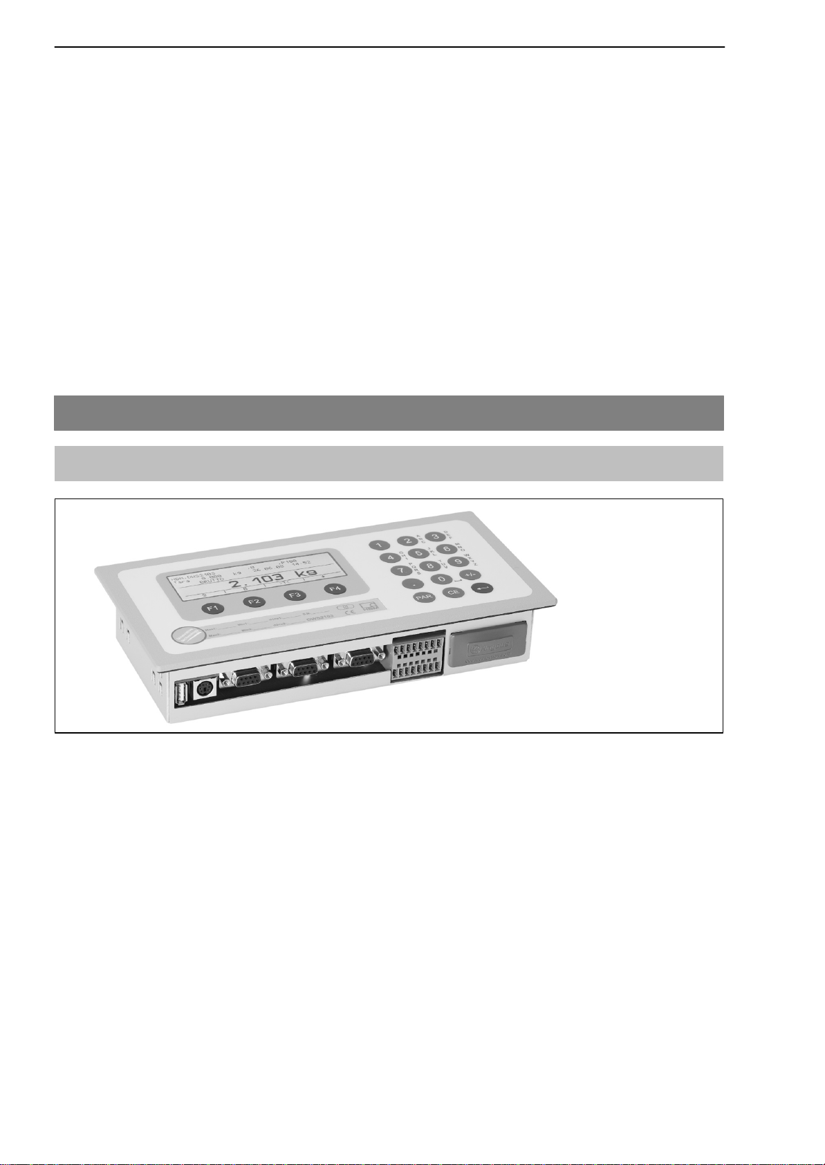
HBM DWS2103 User manual

A2936-1.0 en/de
Digital scale display
Digitale Waagenanzeige
DWS2103
Quick Start Guide
Kurzanleitung

DWS2103
2
HBM A2936-1.0 en/de
Contents Page
Typographical conventions 5. . . . . . . . . . . . . . . . . . . . . . . . . . . . . . . . . . . . .
Important information 5. . . . . . . . . . . . . . . . . . . . . . . . . . . . . . . . . . . . . . . . . .
Safety instructions 6. . . . . . . . . . . . . . . . . . . . . . . . . . . . . . . . . . . . . . . . . . . . .
1 Introduction and appropriate use 7. . . . . . . . . . . . . . . . . . . . . . . . . . . . .
2 Special features 7. . . . . . . . . . . . . . . . . . . . . . . . . . . . . . . . . . . . . . . . . . . . .
3 Mechanical construction and scope of supply 8. . . . . . . . . . . . . . . . .
3.1 Scope of supply 8. . . . . . . . . . . . . . . . . . . . . . . . . . . . . . . . . . . . . . . .
3.2 Accessories, to be ordered separately 9. . . . . . . . . . . . . . . . . . . . .
4 Scale commissioning overview 9. . . . . . . . . . . . . . . . . . . . . . . . . . . . . . .
4.1 Initial commissioning 10. . . . . . . . . . . . . . . . . . . . . . . . . . . . . . . . . . .
4.2 NAWI application 10. . . . . . . . . . . . . . . . . . . . . . . . . . . . . . . . . . . . . .
5 Electrical connections 11. . . . . . . . . . . . . . . . . . . . . . . . . . . . . . . . . . . . . .
5.1 Notes 11. . . . . . . . . . . . . . . . . . . . . . . . . . . . . . . . . . . . . . . . . . . . . . . .
5.2 Cable connection 11. . . . . . . . . . . . . . . . . . . . . . . . . . . . . . . . . . . . . .
5.3 Cable preparation 12. . . . . . . . . . . . . . . . . . . . . . . . . . . . . . . . . . . . . .
5.3.1Connecting DWS2103 with RS485, 4-wire bus 13. . . . . . . .
5.3.2 Connecting DWS2103 with RS485, dignostic bus, 2 wire 14
5.3.3 Connecting DWS2103 with CANOpen bus 15. . . . . . . . . . .
5.4 Load cell connection 16. . . . . . . . . . . . . . . . . . . . . . . . . . . . . . . . . . .
5.5 Supply voltage 16. . . . . . . . . . . . . . . . . . . . . . . . . . . . . . . . . . . . . . . .
5.6 Voltage outputs 17. . . . . . . . . . . . . . . . . . . . . . . . . . . . . . . . . . . . . . . .
5.7 RS485 interface (Terminal block K1) 17. . . . . . . . . . . . . . . . . . . . . .
5.8 Terminal block K1 assignments 18. . . . . . . . . . . . . . . . . . . . . . . . . .
5.9 RS232 interface (COM2) 18. . . . . . . . . . . . . . . . . . . . . . . . . . . . . . . .
5.10 RS232 interface (COM3) 19. . . . . . . . . . . . . . . . . . . . . . . . . . . . . . . .
5.11 RS-232 interface (COM4) 19. . . . . . . . . . . . . . . . . . . . . . . . . . . . . . .
5.12 PS2 keyboard interface 19. . . . . . . . . . . . . . . . . . . . . . . . . . . . . . . . .
5.13 USB printer interface 19. . . . . . . . . . . . . . . . . . . . . . . . . . . . . . . . . . .
5.14 Interface-Schnittstelle (COM5) 19. . . . . . . . . . . . . . . . . . . . . . . . . . .
6 Control and display functions 20. . . . . . . . . . . . . . . . . . . . . . . . . . . . . . .
6.1 Device view 20. . . . . . . . . . . . . . . . . . . . . . . . . . . . . . . . . . . . . . . . . . .
6.2 Operator controls 21. . . . . . . . . . . . . . . . . . . . . . . . . . . . . . . . . . . . . .
6.3 Display 21. . . . . . . . . . . . . . . . . . . . . . . . . . . . . . . . . . . . . . . . . . . . . . .

DWS2103 3
HBMA2936-1.0 en/de
7 Basic scale functions 23. . . . . . . . . . . . . . . . . . . . . . . . . . . . . . . . . . . . . . .
7.1 Switching on and off 23. . . . . . . . . . . . . . . . . . . . . . . . . . . . . . . . . . . .
7.2 Configuration of the load cells 24. . . . . . . . . . . . . . . . . . . . . . . . . . .
7.3 Zero setting the scale 24. . . . . . . . . . . . . . . . . . . . . . . . . . . . . . . . . .
7.4 Gross/net selection 25. . . . . . . . . . . . . . . . . . . . . . . . . . . . . . . . . . . .
7.5 10-fold resolution 25. . . . . . . . . . . . . . . . . . . . . . . . . . . . . . . . . . . . . .
7.6 Taring 25. . . . . . . . . . . . . . . . . . . . . . . . . . . . . . . . . . . . . . . . . . . . . . . .
7.7 Zero on start-up 26. . . . . . . . . . . . . . . . . . . . . . . . . . . . . . . . . . . . . . .
7.8 Error displays 26. . . . . . . . . . . . . . . . . . . . . . . . . . . . . . . . . . . . . . . . .
7.9 Standstill recognition 26. . . . . . . . . . . . . . . . . . . . . . . . . . . . . . . . . . .
8 Alibi and calibration memory 27. . . . . . . . . . . . . . . . . . . . . . . . . . . . . . . .
8.1 Reading the stored files 27. . . . . . . . . . . . . . . . . . . . . . . . . . . . . . . . .
9 Parameter factory settings 28. . . . . . . . . . . . . . . . . . . . . . . . . . . . . . . . . .
10Monitoring functions and error messages 29. . . . . . . . . . . . . . . . . . . .
10.1 Monitoring functions 29. . . . . . . . . . . . . . . . . . . . . . . . . . . . . . . . . . . .
10.2 Error messages 29. . . . . . . . . . . . . . . . . . . . . . . . . . . . . . . . . . . . . . .
11Specifications 32. . . . . . . . . . . . . . . . . . . . . . . . . . . . . . . . . . . . . . . . . . . . . .
Specifications (Continuation) . . . . . . . . . . . . . . . . . . . . . . . . . . . . . . . . . . . .
B-33
12Dimensions (in mm; 1 mm = 0.03937 inches) 34. . . . . . . . . . . . . . . . . .
12.1 DWS2103 and cutout in the panel-frame 34. . . . . . . . . . . . . . . . . .
12.2 Desktop housing, also for wall mounting 34. . . . . . . . . . . . . . . . . .
13Operator dialog and setup parameters 35. . . . . . . . . . . . . . . . . . . . . . .

DWS2103
4
HBM A2936-1.0 en/de

DWS2103 5
HBMA2936-1.0 en/de
Typographical conventions
For clear identification and improved legibility, the following conventions have
been used in this documentation:
NOTE
Important paragraphs are marked with a symbol to draw attention to
them.
Italics Indicates external documents and files
“MODE” All menus and menu commands appear in quotes, here the
main menu “MODE”.
“ENTER” Quotes and italics are used for keys, input fields and user
input.
TAR Bold is used for communication commands.
Er1250 Underlined normal print is used for error messages.
FIT..., PW..., Components of HBM’s digital scale system.
AED... The products are identified by this character
Important information
NOTE
Neither the design of the device nor any technical safety aspects may be mo-
dified without the express permission of Hottinger Baldwin Messtechnik
GmbH. Any modification excludes Hottinger Baldwin Messtechnik GmbH from
any and all liability for any damage resulting therefrom.
When replacing the battery for the real-time clock, the device must be discon-
nected from the power supply (service life 5 years).
It is strictly forbidden to carry out any repairs and soldering work on the mo-
therboards or to replace any components. Repairs may only be carried out by
persons authorized by Hottinger Baldwin Messtechnik GmbH.
The production number set at the factory cannot be changed.
When connecting the cables, the device must be disconnected from the vol-
tage supply.

DWS2103
6
HBM A2936-1.0 en/de
Safety instructions
•There are not normally any hazards associated with the product, provided
the notes and instructions for project planning, installation, appropriate ope-
ration and maintenance are observed.
•Each time, before starting up the modules, you must first run a project planning
and risk analysis that takes into account all the safety aspects of automation
technology. This particularly concerns personal and machine protection.
•It is essential to comply with the safety and accident prevention regulations
specific to the particular application.
•Installation and start-up must only be carried out by suitably qualified personnel.
•Do not allow damp and dirt to get inside the device when connec. the cables.
•When connecting the cables, take action to prevent electrostatic discharge
as this may damage the electronics.
•The required power supply for the device is an extra-low voltage (10...30 V)
with safe disconnection from the mains.
•When connecting additional devices, comply with the safety requirements.
•The ground connections of the supply voltage, the interface and the load
cell cable shield are interconnected in the device. If the potentials of the de-
vices to be connected are different, suitable steps must be taken to isolate
the signals (such as using an optocoupler).
•Shielded cables must be used for all connections apart from the supply vol-
tage (see note below). The shield must be connected to the provided termi-
nals (Chapter 5.3, page 12).
•The use of unshielded cables for the voltage supply is only permissible for
cables with a maximum length of 30 m, laid inside buildings. If cables are
longer or are installed outside buildings, shielded cables must be used (as
per EN 61326−1).
•To compensate for potential differences, the metal housing of the
DWS2103 must be connected to the scale structures as well as to the
ground potential of the connected devices by a low-resistance equalizing
conductor. This is unnecessary if a potential difference of 35 V is not ex-
ceeded.
•In the device, the reference ground (GND) of all the signals and the supply vol-
tage is connected directly to the cable shield connection but not to the housing.
•Connection to a wide-ranging supply network is not permitted as this often
causes interfering voltage peaks to be coupled into the electronics. Instead,
a local supply must be provided for the DWS2103 (even when grouped).
•The front foil is made from high-quality materials, providing a service life
appropriate to the external conditions. The keys must only be operated by
hand; under no circumstances must pointed objects be used to press them.

DWS2103 7
HBMA2936-1.0 en/de
1 Introduction and appropriate use
This Operating Manual contains detailed information both on operation and on
the setting options of the DWS2103 weighing electronics.
The DWS2103 is designed for use in industrial applications, for example
•as a legal−for−trade main display for digital load cells or weighing
electronics (such as FIT, PWxi, ADxx)
•up to 90 when connecting via the RS485 interface
•up to 128 when connecting via the CAN interface
•as the component(s) of a non−automatic scale (NAWI) 1)
•in a check weigher for production monitoring
•in filling and dosing controls.
Use for any purpose other than the above is deemed to be inappropriate.
1) NAWI – non automatic weighing instrument
2 Special features
The DWS2103 is a digital display unit for connection to digital load cells.
The DWS2103 has available:
DRS485 4-wire connection for up to 90 digital load cells or weighing electronics
DCAN interface for up to 128 digital load cells or weighing electronics
DEncrypted transmission of measured values between DWS2103 and con-
nected products in legal−for−trade mode
DCOM port for serial communication with a PC / PLC (RS232)
DCOM port for a printer (RS232 or USB)
DCOM port for an external large−scale display (RS232)
DCOM port for connection to fieldbuses
DPS2 connection for an external keyboard
DInternal SD card as alibi memory for print data and settings
DReal−time clock with battery buffering
DSupply voltage range 10 to 30 VDC
DVoltage output to power supply of digital load cells
The electronics are set and parameterized via keyboard or interface.

DWS2103
8
HBM A2936-1.0 en/de
Additional features:
DUse as one or two−range scale display
DDisabling/enabling of menu functions
DFilter selection
DMax. capacity adjustment, partial load adjustment
DZero on start−up
DAutomatic zero tracking
DWeighing range linearization
DVarious print functions
DNumerous monitoring and error detection functions
3Mechanical construction and scope of supply
3.1 Scope of supply
Fig. 3.1: DWS2103 view
•DWS2103 scale electronics in aluminum housing for panel mounting
•Adhesive label for closing and sealing the opening for the calibration push-
button and labeling strips
•8 labeling strips for creating the scale type plate
•Two 8-pin mating connectors (Phoenix Mini-Combicon mating connector
8 pin Type: MC1.5/8-ST-3.81)
•Two connector housing with strain relief (Phoenix Mini-Combicon connector
housing 8 pin Type: KGG-MC 1.5/9)

DWS2103 9
HBMA2936-1.0 en/de
•4 mounting elements for panel mounting
For DWS2103 panel mounting, the cut guides are bent outward for fitting the
mounting elements. Then, the set screws are used for clamping the housing
to the panel.
•SD card (1 Gbyte) installed in DWS2103
•Quick start guide
•System CD, 1-DWS2103-DOC
3.2 Accessories, to be ordered separately
•Power pack, AC/DC 15 V / 530mA (for max. 8 load cells)
•Desktop housing, also for wall mounting, 1-TG2116 (for Dim. see Chap. 12.2)
•Junction box VKD2R-8
•Cable (connection cable for FIT..., PWxi, AED...)
4 Scale commissioning overview
The permissible supply voltage for the DWS2103 is in the range of
+10...30 VDC and must be adequately smoothed (rms value less residual rip-
ple >10 V).
NOTE
When the C16i digital load cell is supplied via the DWS2103, the permis-
sible supply voltage is +10 ... 17 VDC
Type FIT, PW...i and AED... digital load cells can be operated with +10 to 30 VDC.
A 100...240 V power supply unit is available as an accessory (AC/DC15 V / 530
mA, for max. 8 load cells). This power pack is suitable for all digital load cells.

DWS2103
10
HBM A2936-1.0 en/de
When properly connected with shielded cables, the DWS2103 complies with
the relevant European standards and carries the CE mark.
A formatted SD card with the parameters of the factory setting is inserted in
the device.
Mechanical dimensions are described in chapter 12 (page 34 ) and mounting
information in chapter 3, page 8 .
Subsequent sub-chapters provide an overview of the sequence of steps that
need to be taken to commission the scale, depending on the application:
•Initial commissioning
•As a component of a non-automatic scale (NAWI)1) Chapter 4.1 (page 10)
This overview includes information on the respective chapters in this Opera-
ting Manual.
1) NAWI – non automatic weighing instrument
4.1 Initial commissioning
•Mounting the device, Chapter 3 (page 8)
•Connecting the digital load cell(s), Chapter 5 (page 11) and 5.4 (page 16)
•Connecting the supply voltage, Chapter 5 (page 11) and 5.5 (page 16)
•Connecting the serial connections, Chapter 5 (page 11), 5.8 (page 18) up
to 5.14 (page 19)
•Switching on the device, Chapter 7.1 (page 23)
•Configuration of the load cells, Chapter 7.2 (page 24)
4.2 NAWI application
•Mounting the device, Chapter 3 (page 8)
•Connecting the digital load cell(s), Chapter 5 (page 11) and 5.4 (page 16)
•Connecting the supply voltage, Chapter 5 (page 11) and 5.5 (page 16)
•Connecting the serial connections, Chapter 5 (page 11), 5.8 (page 18) or
5.9 (page 18)
•Switching on the device, Chapter 7.1 (page 23)
the following steps are described on the system CD:
•Calling the parameter menu via the hidden key
•Enabling all menu functions

DWS2103 11
HBMA2936-1.0 en/de
•Configuration of the load cells
•Setting the weighing range
•Setting the correct filters
•Adjusting the weighing range
•Linearization (only when necessary)
•Settings for legal-for-trade applications
•Parameter settings for serial interfaces
•Setting the date and time
•Disabling menu functions (if necessary)
•Filling out the labeling strip, securing the labeling strip
•Checking settings and functions
5 Electrical connections
5.1 Notes
Please observe the safety information at the start of this description.
The load cells and the supply cables are connected by means of screw termi-
nals on the back of the device. The terminals are fitted with wire protection
and the use of end sleeves is recommended, particularly for the load cell ca-
bles. The assignment of the connection terminals is displayed on the back of
the device.
NOTE
All the ground connections are interconnected on the motherboard!
5.2 Cable connection
All connections are accessible from the outside, the housing does not need to
be opened. Strain relief for the connection cable can be implemented via the
supplied terminal housing. It permits the use of round cables with a diameter
of 5...7 mm.
To minimize EMC problems, the individual wires from the end of the shielding
to the terminal should be as short as possible.
The cable shieldings must be twisted together and connected to one of the
terminals 1.1, 1.8, 2.1 or 2.8.

DWS2103
12
HBM A2936-1.0 en/de
5.3 Cable preparation
•Remove the outer sheath about 20 mm.
•Twist braided shield.
•If necessary, remove the inner sheath.
•Strip the wire ends about 5 mm.
•Connect the wires to the terminals.
Shielding
ÎÎÎÎÎÎ
ÎÎÎÎÎÎ
Versorgungssp.ng
+10...30 VDC
Output voltage
+10...30 VDC
GND
Ground
Output voltage
+10...17 V*
GND
Shielding
Shielding
Shielding
Shielding
COM 1 Load cell
TB (RB)
TA (RA)
RB
RA
* for C16i load cells
CAN-LOW
CAN-HIGH
Fig. 5.1: Position of connections on terminal block K1

DWS2103 13
HBMA2936-1.0 en/de
5.3.1 Connecting DWS2103 with RS485, 4-wire bus
4−wire RS485 DWS2103
Terminal K1
Shielding connection 1.1
RS485, transmission line A (=T−) 1.7 RA (RX−)
RS485, transmission line B (=T+) 1.6 RB (RX+)
RS485, reception line A (=R−) 1.5 TA (TX−)
RS485, reception line B (=R+) 1.4 TB (TX+)
Voltage supply +, max. 30 VDC 2.2 UB
Voltage supply ground 2.4 GND
2.2 UB
2.4 GND
1.6 RB (RX+)
1.7 RA (RX−)
1.4 TB (TX+)
1.5 TA (TX−)
GND
UB
RB (RX+)
RA (RX−)
TB (TX+)
TA (TX−)
AED/FIT
RS485 / 4−wire BUS
GND
UB
RB (RX+)
RA (RX−)
TB (TX+)
TA (TX−)
2.2 = UOUT1
K1
DWS2103
AED/FIT
Fig. 5.2: Cable assignment

DWS2103
14
HBM A2936-1.0 en/de
5.3.2 Connecting DWS2103 with RS485, dignostic bus, 2 wire
For bus termination, comply with documentation provided for the connected
devices. Only devices of the same type must be connected to the bus.
2−wire RS485 (diagnosis) DWS2103
Terminal K1
Shielding connection 1.1
RS485, (transmission/reception line A (=R−/T−) 1.5 TA (TX−) / RA (RX−)
RS485, (transmission/reception line B (=R+/T+) 1.4 TB (TX+) / RB (RX+)
Voltage supply +, max. 30 VDC 2.2 UB
Voltage supply ground 2.4 GND
2.2 UB
2.4 GND
1.4 TB (TX+) / RB (RX +)
1.5 TA (TX−) / RA (RX −)
GND
UB
TB (TX+) / RB (RX+)
TA (TX−) / RA (RX−)
AED/FIT
RS485 / 2−wire BUS
GND
UB
2.2 = UOUT1
K1
DWS2103
AED/FIT
TB (TX+) / RB (RX+)
TA (TX−) / RA (RX−)
Fig. 5.3: Cable assignment

DWS2103 15
HBMA2936-1.0 en/de
5.3.3 Connecting DWS2103 with CANOpen bus
For bus termination, comply with documentation provided for the connected
devices. Only devices of the same type must be connected to the bus.
CANOpen bus DWS2103
Terminal K1
Shielding connection 1.1
CAN HIGH 2.7 CAN HIGH
CAN LOW 2.6 CAN LOW
Voltage supply +, max. 30 VDC 2.2 UB
Voltage supply ground 2.4 GND
2.2 UB
2.4 GND
2.6 CAN LOW
2.7 CAN HIGH
AED/FIT
CANOpen BUS
2.2 = UOUT1
K1
DWS2103
AED/FIT
120-Ω-bus termination resistor
CAN HIGH
CAN LOW
CAN HIGH
CAN LOW
GND
GND
UB
UB
Fig. 5.4: Cable assignment

DWS2103
16
HBM A2936-1.0 en/de
5.4 Load cell connection
Only digital load cells or weighing electronics (FIT, AED, PWxi) can be con-
nected to DWS2103. An RS485 interface and a CAN interface are available
on DWS2103 for this purpose.
Load cells and weighing electronics can be operated via the main channel on
DWS2103 as well as via the diagnostic channel. Care must be taken to en-
sure that all weighing units connected to the BUS are connected either via the
main channel or via the diagnostic channel.
There is a choice of interface to use with the weighing units:
Main channel: RS485 4-wire (full duplex), RS485 2−wire (half duplex)
or CAN
Diagnostic channel: RS485 2-wire (half duplex) fixed baud rate 38400 Bd,
even parity
Mixed operation of the main and diagnostic channels is not permissible, nor is
using different interfaces (RS485, CAN).
Factory settings for all digital weighing units (such as FIT, AED, etc.), are ad-
dress 31 (for RS485) and address 63 (for CAN).
If several load cells with factory settings are connected to a scale, the load
cell addresses must first be changed. These settings are made in the ”BUS
SCAN” parameter menu.
NOTE
Call up the parameter menu ”BUS SAN” after connecting the load cells.
5.5 Supply voltage
Terminal Function Comments
1.2 Supply voltage +10...30 VDC 1)
1.3 Ground
1) The supply voltage must be sufficiently filtered (rms value minus residual ripple > 10V).

DWS2103 17
HBMA2936-1.0 en/de
5.6 Voltage outputs
Terminal Function Comment
2.2 Output
voltage
10 ... 30 V
The input voltage 10 ...30 V is made available directly at the
output to supply digital load cells.
2.4 GND Ground
2.3 Output
voltage
10 ... 17 V
This output is used to supply C16i load cells with a maximum
supply voltage of 17 V.
The input voltage is made available at the output up to a
value of 17 V. The output is switched off at higher input volt-
ages.
2.5 GND Ground
1.1, 1.8, 2.1,
2.8 Shielding
5.7 RS485 interface (Terminal block K1)
The DWS2103 is the master for the connection with the digital load cells (C16i,
measurement chain).
COM5 COM3 COM4 PS2 USB
Terminal block K1
COM2
Fig. 5.5: Connection positions (back of device); assignment, see page 14

DWS2103
18
HBM A2936-1.0 en/de
5.8 Terminal block K1 assignments
The terminal block K1 has the following signals:
− Supply voltage input
− Supply voltage load cell output
− RS485 4−wire load cell interface
− CAN load cell interface (dependent on load cell) for future applications
Terminal Signal Comments
1.1,1.8
2.1,2.8 Shielding
1.2 Supply voltage 10...30 V
1.3 Supply voltage GND
1.4 COM1 load cell TB (RB) Serial interface
RS485
Only the terminals 1.4
and 1.5 must be used for
RS485 2−wire
1.5 COM1 load cell TA (RA)
1.6 COM1 load cell RB
1.7 COM1 load cell RA
2.2 Voltage output 10...30 V Output voltage
= input voltage
2.3 Voltage output supply
C16i 10...17 V With input voltage
> 17 V this output does
not supply voltage
2.4, 2.5 Voltage output GND
2.6 COM1 load cell CAN_low CAN interface
2.7 COM1 load cell CAN_high
5.9 RS232 interface (COM2)
COM2 computer interface for connection to a PC via SUB−D 9-pin socket
The SUB-D socket is assigned so that a standard RS232 cable can be used.
1
59
6
1
2 RS232-TX
3 RS232-RX
4
50V
6
7
8

DWS2103 19
HBMA2936-1.0 en/de
5.10 RS232 interface (COM3)
COM3 printer interface for connection of a serial printer via SUB−D 9-pin sok-
ket. The SUB-D socket is assigned so that a standard printer cable can be
used.
1
59
6
1 −−−
2 RS232-TX
3 RS232-RX
4 DSR (DTR from printer)
50V
6
7
8
9
5.11 RS-232 interface (COM4)
COM4 interface for connection of a second display via SUB−D 9-pin socket.
The SUB-D socket has the PC standard assignment.
1
59
6
1 −−−
2 RS232-TX
3 RS232-RX
4 DSR (DTR from second display)
50V
6
7
8
9
5.12 PS2 keyboard interface
Input for connection of an external standard keyboard.
5.13 USB printer interface
USB host socket for connection of a printer.
5.14 Interface-Schnittstelle (COM5)
COM5 is set up as an optional interface for a fieldbus module.
The function and assignment is described together with the Anybus plug-in
module.

DWS2103
20
HBM A2936-1.0 en/de
6 Control and display functions
6.1 Device view
The front of the DWS2103 consists of the following elements:
98
1
23
4
5
6
7
Fig. 6.1: DWS2103 front panel
1. Info line 1; configurable in the menu ”Display →Display line 1”
2. Info line 2; configurable in the menu ”Display →Display line 2”
3. Measurement status display
4. Measurement value display
5. Function line (meaning of function keys F1 ...F4)
6. Function keys F1 ... F4
7. Hidden pushbutton for access to the calibration menu. The pushbutton can
be accessed with a pointed object (when the label is removed). After cali-
bration, the opening is sealed with the enclosed adhesive label or, for legal-
for-trade applications, with the calibration label. Device calibration is pro-
tected during operation and can only be changed when this pushbutton is
actuated.
8. Inspection window for inserting a labeling strip (for scale type plate with ca-
libration data, device name, etc.).
9. Keyboard for entering numbers and letters
The connections for serial interfaces and the terminals for the connection ca-
bles are located on the back of the device.
Table of contents
Languages:
Other HBM Scale manuals