HBS C 08 User manual

C 08
Welding Gun
92-20-262
Operating Manual

ii
ii C 08 Order No. BA 92-20-262 Issue 01.03.08
C 08 Operating Manual, Issue 03/2008 Order No. BA 92-20-262
Customer Service in Germany:
HBS Bolzenschweiss-Systeme GmbH & Co. KG
Felix-Wankel-Strasse 18
85221 Dachau / Germany
Phone +49 (0) 8131 511-0
Fax +49 (0) 8131 511-100
E-mail [email protected]
Web www.hbs-info.com
Copyright:
The information contained herein may not be copied, reproduced, adapted,
merged, translated or used without the prior written consent of the copyright
owner.
Adaptations, errors and technical modifications reserved without prior notice.
©HBS Bolzenschweiss-Systeme GmbH & Co. KG

iii
C 08 Order No. BA 92-20-262 Issue 01.03.08 iii
Dearcustomer,
ThankyouverymuchforpurchasingaweldinggunfromHBSBolzenschweiss-
Systeme.
We from HBS wish you always successful working with this stud welding unit.
We ask you to observe the following points:
– Store the operating manual in a way that it can always be accessed by the
operator.
– Letthe operatorsign beforestarting upthat hehas readand completelyunder-
stoodtheoperatingmanual.
– This operating manual applies only to this stud welding unit.
– Protectthe stud welding unit from unauthorized use.
– Thestud welding unit must only be operatedby trainedpersonnel.
– Let an electrician check whether the wall sockets where you want to connect the
relatedstudweldingunit,areproperlyfusedandgrounded.
– Informourcustomerserviceincaseofmalfunction.
– In case of accident, inform a physician and the responsible official body.
THREATTOLIFE!
Persons fitted with a pace maker must not operate the stud
welding machine.
MAGNETICFIELDS!
During stud welding, strong electro-magnetic fields are
generated. Do not weld in the vicinity of the electrical
equipment which could be affected.
Safety instructions are a delicate subject. Anybody who handles a stud welding
unit, whether it is the welding gun or the power unit, should be familiar with them,
becauseimproper use of stud welding units canbe dangerous to life.
For your own sake you should know the safety instructions for operating your HBS
stud welding units inside out.
In addition to the protection of your health and the capital value of the enterprise, the
safety instructions are intended to clarify any responsibilities, which arise from
ownershipandoperationoftheequipment.
Thischapteroftheoperatingmanualoffersyouclearandeasytounderstandinformation
forthe safeoperation ofyour HBS stud welding unit.

iv
iv C 08 Order No. BA 92-20-262 Issue 01.03.08
Yourweldinggunmaydifferinsomedetailsfromthecaptionsinthismanual.Thishas
noeffectontheoperation of the weldinggun.
Shouldyouhavequestionsaboutthismanualorincaseyouwanttoordersomemore
copies,please provide the order numberlisted inthe foot line.
Importantreminder:
Dataandinformationhereinwerecollectedwithgreatestcare.Althoughwedidourvery
besttocorrectlyupdateanyinformationuptothetimeofdelivery,thereisnoguarantee
inrespectoferrors.
If you should detect errors or mistakes right in this manual, please contact us:
HBS Bolzenschweiss-Systeme GmbH & Co. KG
Felix-Wankel-Strasse18
85221Dachau/Germany
Afeedback blank is provided in the appendix.

C 08 Order No. BA 92-20-262 Issue 01.03.08 v
Table of Contents
Table of Contents
1 General .............................................................................................7
1.1 Guide to this Operating Manual .................................................................... 8
1.2 Safety Symbols ............................................................................................ 9
1.3 General Safety Instructions ........................................................................ 10
1.4 IntendedUse .............................................................................................. 10
1.5 Transportation, Packaging, Storage ........................................................... 11
1.6 Accompanying Documents ........................................................................ 11
1.7 Markings ..................................................................................................... 12
2 Delivery...........................................................................................13
3 Starting-up .....................................................................................14
3.1 Requirements of Workplace ...................................................................... 14
3.2 Connecting the Welding Gun to the Power Unit ......................................... 15
3.3 Ground Connection .................................................................................... 16
3.4 Change Working Place .............................................................................. 17
4 Function .........................................................................................18
4.1 Components of the Welding Gun ............................................................... 18
4.2 Adjustment of Chuck .................................................................................. 19
4.3 Installation of Chuck ................................................................................... 20
4.4 Adjustment of Spring Force........................................................................ 21
5 Stud Welding Procedure............................................................... 22
5.1 Safety Instructions...................................................................................... 22
5.2 Functional Principle of Stud Welding.......................................................... 25
5.2.1 Contact Stud Welding ............................................................................................ 25
5.3 Welding Preparation................................................................................... 26
5.4 High-strength Welds................................................................................... 26
5.5 Determination of Welding Parameters ....................................................... 26
5.6 Welding Procedure .................................................................................... 28

vi C 08 Order No. BA 92-20-262 Issue 01.03.08
Table of Contents
5.7 Checking the Quality of the Weld ............................................................... 29
5.7.1 VisualInspection ................................................................................................... 29
5.7.2 BendingTest.......................................................................................................... 30
5.7.3 Arc Blow Effect ...................................................................................................... 32
5.8 Malfunctions and CorrectiveActions .......................................................... 33
5.9 Welding Elements ...................................................................................... 34
6 Switching off the Welding Gun .....................................................36
6.1 Temporary Switching off............................................................................. 36
6.2 Disposal ..................................................................................................... 36
7 Care and Maintenance ..................................................................37
7.1 Safety Instructions...................................................................................... 37
7.2 Regular Maintenance Operations ............................................................... 38
8 Appendix ........................................................................................39
8.1 Technical Data............................................................................................ 39
8.2 Spare Parts ................................................................................................ 40
8.3 Accessories ............................................................................................... 42
8.4 EnvironmentallyAdmissible Disposal......................................................... 48
Glossary .........................................................................................49
Regulations and Standards ..........................................................50
Further Instructions....................................................................... 52
Guarantee Clauses ........................................................................53
Confirmation ..................................................................................54
Feedback........................................................................................55
Service & Support ......................................................................... 56
Index ...............................................................................................57

C 08 Order No. BA 92-20-262 Issue 01.03.08 7
1 General
Persons addressed by this operating manual
Thisoperatingmanualiswrittenforoperators,personneloftheenduser,andauthorized
servicetechnicians.Itprovidesyouwithallnecessaryinformationtooperatethewelding
gun.
Required user qualification
Theweldinggunmustonlybeoperatedbyqualifiedpersonnel.
Letthe welding gun only be operated by persons who
– arequalifiedthroughasuitabletrainingaccordingtothecurrentstandards(see
appendix),
– areproperlyinstructed,
– are physically and intellectually suitable,
– can be expected to reliably fulfill the requested job.
What else must the owner observe?
Make sure that this operating manual is always in reach of the stud welding unit.
Readtheentiremanualbeforeoperatingtheweldinggun.
Strictly observe the safety instructions.
Before starting up the welding gun, let the operator sign the confirmation that he/
shehasreadandfullyunderstoodtheoperatingmanual(seeappendix).
Donotcommencestudweldinguntilyouhaveunderstood alloperatingproces-
ses.
Contactus if thereare any doubts on certainoperating procedures.
Protectthe power unitagainst unauthorized use.
Informourserviceincaseofmalfunction.
Basedonthisoperatingmanual,acompanyspecificworkorder,aswellasacompany
specificmaintenanceinstructionmustbedrawnup.Thecompanyspecificworkorder
must consider the special user conditions in your company.
Makesurethatoperatorsofthewelderareprovidedwithandwearpersonalprotective
equipment,e.g.protective goggles, gloves, shoes,ear protection etc.
Owners and operators make sure that the welding gun is only used as directed.
Duringanyactivitysuch as transportation, set-up, (re-)assembly,production,
maintenanceetc.observetheinformationgiveninthisoperatingmanual.
1 General

8 C 08 Order No. BA 92-20-262 Issue 01.03.08
1.1 Guide to this Operating Manual
Thisoperatingmanualprovidesyouwiththefollowinginformation
“Delivery“ in Chapter2
“Starting-up“ in Chapter 3
“FunctionalPrinciple“ inChapter 4
“StudWelding Process“ in Chapter 5
“SwitchingofftheWeldingGun“ in Chapter 6
“CareandMaintenance“ in Chapter 7
TechnicalData andmuch more in the Appendix
THREAT TO LIFE and risk of serious health and material damage in
case of improper use of the welding gun. Observe all notes in this
operating manual.
Note for qualified operators (see chapter 1).
All instructions contained in this manual must also be obser-
ved by qualified operators.
The welding process and the sequence of procedures to
carry out a weld are described in chapter 5.
1 General
1.1Guide to this Operating Manual
C 08 Order No. BA 92-20-262 Issue 01.03.08 9
1.2 Safety Symbols
Symbols and markings used in this operating manual mean:
Threat to life or risk of personal injury
Risk of material damage
Ban for persons fitted with a pace maker
Warning of dangerous electrical voltage
Warning of electromagnetic fields
Wear protective clothes
Wear protective goggles
Wear ear protection
Additional tips for operation and service safety
Prompt
– List
1 General
1.2 Safety Symbols

10 C 08 Order No. BA 92-20-262 Issue 01.03.08
1.3 General Safety Instructions
Improper operation of the stud welding unit is LIFE-THREA-
TENING!
Threat to life
- by electric shock and arc
- by toxic vapours and airborne particles
- by red-hot metal spatters (fire risk)
- by blow-up of explosive gases and materials
- by strong magnetic fields for persons fitted with a pace maker
In addition, through improper use damage to the stud welding unit
and to material can be caused. For details, see chapters 1, 3 and 5.
1.4 Intended Use
Warning: Unauthorized interference with the stud welding
unit as well as unauthorized alteration of the stud welding
unit are prohibited and result in complete cancellation of any
guarantee and liability claims against HBS.
Operation of welding gun is only allowed with HBS power
units, this clause is also part of “use as directed“.
The welding gun is intended to weld welding elements according to actual standards
(seechapter5andappendix).Anyotheruseisregardedasnotusedasdirected.The
manufacturerisnotliablefordamagesresultingfromthestudweldingunitnotusedas
directed. Any risk is carried by the user.
Theweldinggunisdesignedaccordingtospecificstandardsandaccidentprevention
regulations. Basics are European Union guidelines and in Germany valid standards.
Pleasenotethatinyourcountryadditionalstandardsandsafetyconditions(especially
rulesforaccidentprevention)maydifferfromthestandardsmentionedinthisoperating
manual.Theweldinggunwasmanufacturedtothelatestdevelopmentsintechnology
and is regarded as safe to operate (place of operation see section 8.1).
The welding gun C 08 can be connected to the HBS power units CD 1501, CD 2301,
CD 3101,CDM1601,CDM2401andCDM3201.FordetailspleasecontacttheHBS
customerservice(addressseepage ii).
Check in any case the operating manual of the HBS power unit whether this
weldingguncanbeused.
Observing the operating manual of the used power unit is also part of the „use as
directed“.
1 General
1.3GeneralSafetyInstructions

C 08 Order No. BA 92-20-262 Issue 01.03.08 11
1.5 Transportation, Packaging, Storage
HBSdelivers productsin aspecific transportpackage.
Savethe undamaged packing. Ship andtransport the device only inits original
packing.
Rightbeforedelivery,theweldinggunisonceagaincheckedforproperfunctioningand
acontrolmarkisattached.Whenreceivingthedelivery,checkeverythingfordamages
and completeness. If damages occurred during transportation or components are
missing,inform the manufactureror the haulier immediately (seepage ii).
Properfunctioningoftheweldingguncanonlybecheckedbeforestarting-upbyvisual
inspection(visibledamage).
Thefollowingitemsaretobeobservediftheweldinggunisnottobeputintooperation
immediatelyafterdelivery.
– The welding gun must be stored in a secure place
– The welding gun must be protected against humidity, dust, metallic dirt.
– Storagetemperature: -5 °C to +50 °C
– Relativehumidity: 0% to 50% at +40 °C
0% to 90% at +20 °C
Ifyou resell the welding gun, please provide us withthe name and postal address
of the new owner so that we can advise them of any changes to the operating
manual.
1.6 Accompanying Documents
Inadditiontothisoperatingmanual,youmustobservetheoperatingmanualofthepower
unit as well as applicable accident prevention and safety instructions.
1 General
1.5Transportation,Packaging,Storage

12 C 08 Order No. BA 92-20-262 Issue 01.03.08
1.7 Markings
There are various markings and safety symbols attached to your power unit (see
section 8.1).
Make sure that all markings remain clearly visible.
Type plate
Thetype plate contains the following data:
Manufacturer
Type
OrderNo./SerialNo.
Primaryvoltage
Fuse
Powerconsumption
Cooling class
Protection class
Date
Safetysymbols
Replace illegible or damaged markings
Before opening machine disconnect mains
Observe operating manual
Warning of dangerous electrical voltage
Secure the following safety symbols in the area of welding place:
1 General
1.7Markings
C 08 Order No. BA 92-20-262 Issue 01.03.08 13
2 Delivery
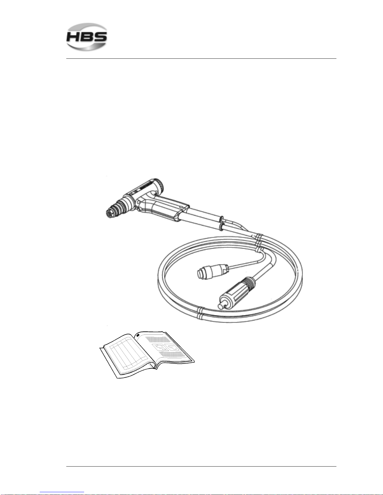
Thebasic equipment of yourweldingguncontainsthefollowingcomponents:
No. of pieces Part Type OrderNo.
1 Gun cable length 6.5 m C08 92-20-262
1 Operatingmanual C08 BA92-20-262
2 Delivery

14 C 08 Order No. BA 92-20-262 Issue 01.03.08
3 Starting-up
Inthischapteryoulearnwhattoobserveduringsetting-upandstarting-upofthewelding
gun.
3.1 Requirements of Workplace
The welding gun protection is to class IP 20. Do not use the
welding gun in humid environment!
Vapors and airborne particles may occur during stud welding
operations. Especially with surface treated materials, toxic
vapors may be produced.
Ensure that a fume extraction is available and that the room is adequately
ventilatedaccordingtoaccidentpreventionregulations.
If possible, do not weld in rooms which are lower than 3 meters.
Specialregulationsapplyforconfinedrooms,accordingtoaccidentprevention
regulationsoftheofficialbodies(seeappendix).
Weld only in adequate distance from combustible articles or liquids.
Before you start welding, remove any combustible articles or liquids in vicinity of
theworkplace.
Make sure that a fire extinguisher is within reach.
Never weld in rooms exposed to risk of explosion.
Do not set-up the product in the vicinity of any apparatus or equipment which is
sensitivetoweldingspatters.
Do not set-up the product in the vicinity of any apparatus or equipment which is
sensitiveto magnetic fields.
Set-uptheweldinggun:
– ona stable, clean andlevel surface
– so that no-one is influenced or injured by welding spatters
– so that all cables and primary lines are protected from being damaged
– so that nobody will trip or fall over the cables or connection lines.
Ensure that air is able to circulate freely through the housing.
If heat is built-up inside the housing caused by bad air
circulation, the stud welding unit will be seriously damaged.
3 Starting-up
3.1RequirementsofWorkplace
C 08 Order No. BA 92-20-262 Issue 01.03.08 15
Secure the following safety symbols in the area of welding place:
THREAT TO LIFE to persons fitted with a pace maker
Strong electro-magnetic fields occur in the vicinity of the stud
welding unit during welding. Such fields may affect the proper
function of a pace maker. Thus persons equipped with a pace
maker must not operate the stud welding unit and must not stay in
its vicinity during welding.
During the actual welding process, you must expect red-hot
welding spatters, possibly liquid spatters, a flash, and a loud bang
> 90 dB (A). Alert any colleagues who are occupied in the vicinity of
the welder.
Wear your personal protective equipment according to actual
standards (see appendix).
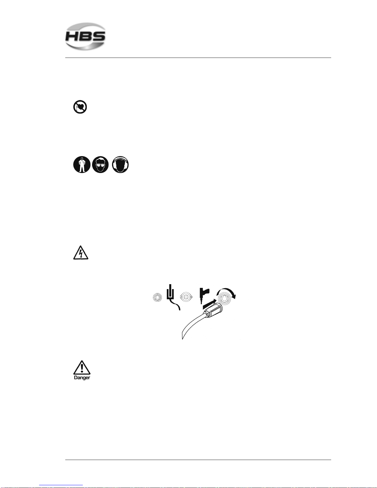
3.2 Connecting the Welding Gun to the Power Unit
Switch off the power unit. In this way, you avoid any risk of
electrical shock.
Plug the welding cable of the welding gun into the socket of the power unit.
Press-in the plug and twist firmly clockwise.
The connection is not secured against working itself loose!
Check the plug connections regularly to ensure that they are
properly locked. In case of loose connection, heat may build
up in the plug and may destroy the entire plug connection.
3 Starting-up
3.2 Connecting the Welding Gun to the Power Unit

16 C 08 Order No. BA 92-20-262 Issue 01.03.08
Plug the control cable of the welding gun into the appropriate connection of the
powerunit.
Twist the retaining nut of the control cable connector clockwise to secure the
connection.
The welding gun cables must not be coiled during welding.
Coiled cables work as a coil and may negatively affect the
welding result. Before welding, lay out the cables
lengthwise.
Fix the cables. Strong magnetic fields occur during welding which may cause a
movement of the cables. This may cause a slackness of the connections.
3.3 Ground Connection
Plug the ground cable in the connector of the power unit.
Press in the plug and twist firmly clockwise.
The connection is not secured against working itself loose!
Check the plug connections regularly to ensure that they are
properly locked. In case of loose connection, heat may build
up in the plug and may destroy the entire plug connection.
Removeany rust, paint,or contaminants from the workpiecein the areaswhere
you intend to connect the ground cables.
3 Starting-up
3.3GroundConnection
C 08 Order No. BA 92-20-262 Issue 01.03.08 17
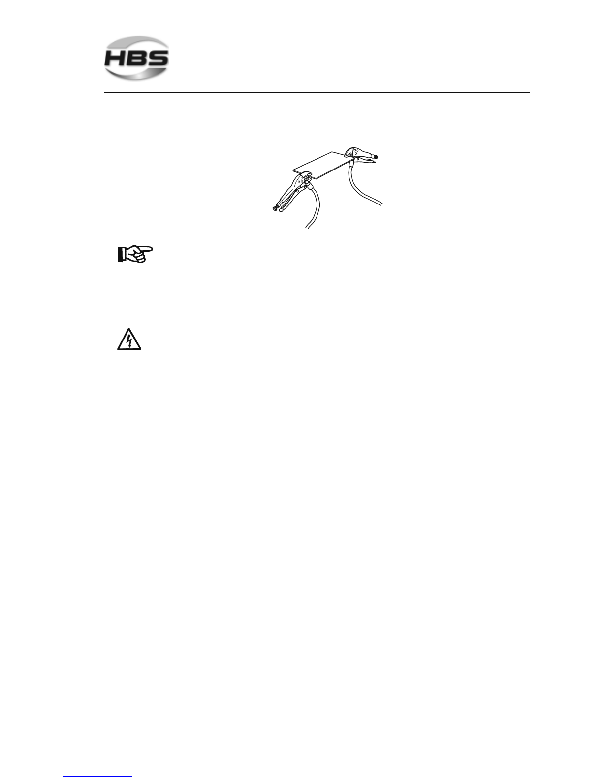
Connect the ground clamps to the workpiece as securely as possible.
Take care to ensure good contact and symmetrical connec-
tion. The welding location must lie directly between the two
ground clamps.
3.4 Change Working Place
Switch off the power unit. In this way, you avoid any risk of
electrical shock.
Whenyoumove your workplace, disconnectthewelding gun andtheground
cablesfromthe power unit.Proceed in reversed sequenceas described in
section 3.2 and 3.3.
Afterchanging the workplace, check thewelding gun and the ground cables for
possibledamage or missing components.
3 Starting-up
3.4ChangeWorkingPlace

18 C 08 Order No. BA 92-20-262 Issue 01.03.08
4 Function
In this chapter you learn more about the design of the welding gun and how to use the
varioussettingoptions.
4.1 Components of the Welding Gun
The body of the welding gun consists of a sturdy two-part plastic housing (1).
Thecontrolcable andtheweldingcable(2)areconnectedthroughtheweldinggun
handletothe welding gun.
Positionedatthefrontoftheweldinggunaretheweldingpistonandtheretainingnut
(3) used to fix the manual chuck.
At the rear, there is the mechanism for spring force adjustment (5).
Atthefrontoftheweldinggunhandle,theweldingguntrigger(6)isinstalled.Itisused
totrigger the welding process.
The serial number (7) can be found on the welding gun handle.
4 Function
4.1ComponentsoftheWeldingGun

C 08 Order No. BA 92-20-262 Issue 01.03.08 19
4.2 Adjustment of Chuck
Various chucks for different stud diameters are available as unit accessories (see
appendix).
Select the chuck which fits the diameter of your welding element.
Put the welding element into the chuck. In the chuck, there is an adjustable stop
pin.
Loosentheretainingnut.
Twist the stop pin in the chuck in a way that
– the unthreaded part of the pin is inside the chuck (for welding elements
up to 20 mm length),
– the unthreaded part of the pin projects is out of the welding element
(forweldingelementsabove20mmlength).
As special accessory, a stop pin for welding elements with
internal thread is available.
Adjust the standard stop pin in such a way that an overall distance of 50 mm is
obtainedbetween upper face oftheretainingnutandbottomofthe welding
element.
4 Function
4.2 Adjustment of Chuck

20 C 08 Order No. BA 92-20-262 Issue 01.03.08
Retightentheretainingnut.
Retighten regularly and carefully the chuck at the four
segments (see figure below, at the visible end of the chuck)
using pliers to ensure a proper current transition. This will
prevent early wear through spark erosion.
4.3 Installation of Chuck
Put the chuck with loose retaining nut up to the stop into the piston of the
weldinggun.
Tighten the retaining nut with the socket wrench SW 17.
4 Function
4.3Installation of Chuck
Other manuals for C 08
2
This manual suits for next models
1
Table of contents
Other HBS Welding System manuals


