HBS CDi 502 User manual

©HBS Bolzenschweiss-Systeme GmbH & Co. KG
All rights reserved – Reprinting, in whole or in part, only with the approval of the manufacturer
Operating Manual
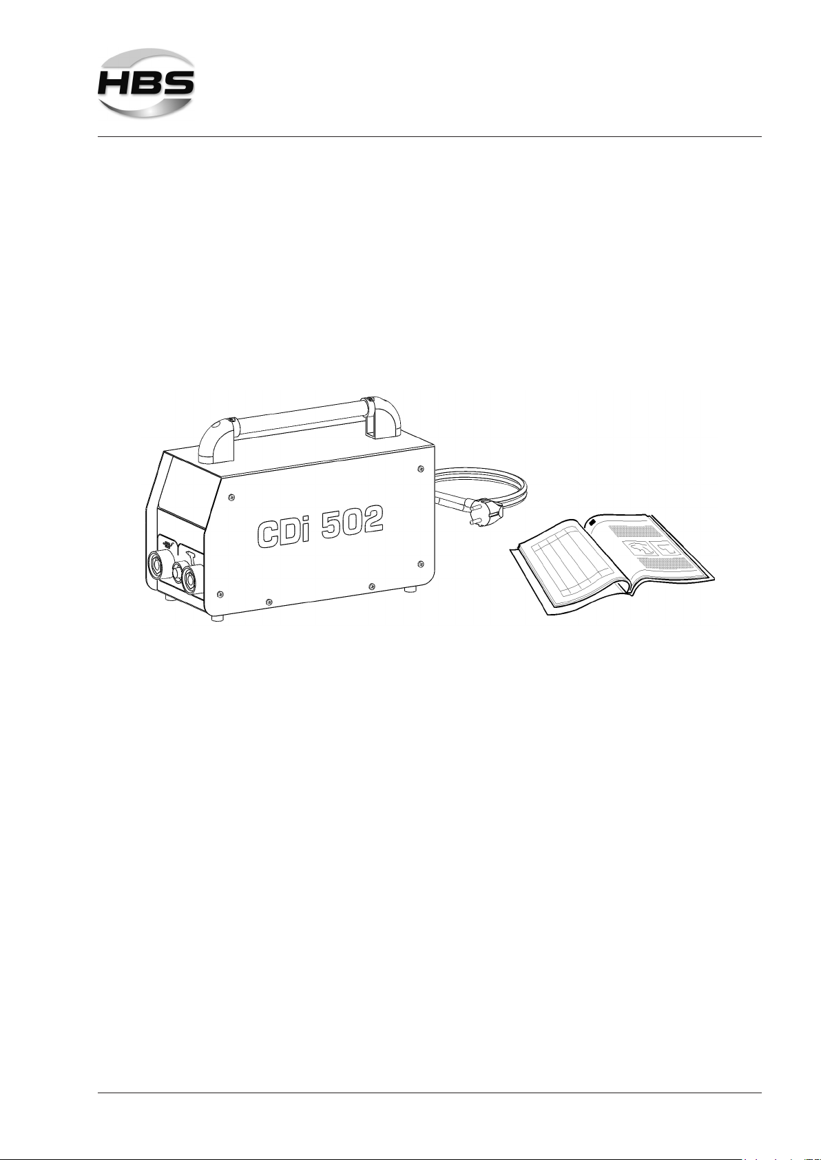
CDi 502
Stud Welding Unit
92-10-0502
2021

2
After-sales service for Germany:
HBS Bolzenschweiss-Systeme GmbH & Co. KG
Felix-Wankel-Strasse 18
85221 DACHAU
GERMANY
Phone +49 8131 511-0
Fax +49 8131 511-100
E-mail [email protected]
Web www.hbs-info.com
CDi 502 Operating Manual Issue 2021-01 Order No. E-BA 92-10-0502
Translation of the Original Operating Manual
Please keep the manual in a safe place for future reference.
Transmission and duplication of this document, dissemination and notication
of the contents are not permitted unless expressly approved.
All rights, errors and technical amendments reserved.
© HBS Bolzenschweiss-Systeme GmbH & Co. KG

3©HBS Bolzenschweiss-Systeme GmbH & Co. KG
All rights reserved – Reprinting, in whole or in part, only with the approval of the manufacturer
Dear Customer,
Many thanks for buying a stud welding machine from HBS Bolzenschweiss-Syste-
me.
We at HBS wish you success at all times when working with this stud welding ma-
chine.
The high level of quality of our products is guaranteed by ongoing further deve-
lopment in the design, equipment and accessories. This may result in differences
between the present operating manual and your product. No claims can therefore be
derived from the data, illustrations and descriptions.
We have compiled the data and information in this reference work with the greatest
care, and have made every effort to ensure that the information contained in this
manual was correct and up-to-date at the time of delivery. We can nevertheless give
no guarantee for an absolutely error-free document.
Should you discover any errors or unclear points when reading this operating manu-
al, please do not hesitate to contact us.
We would also be grateful for any feedback should you have any suggestions or
complaints to make about our product.
HBS Bolzenschweiss-Systeme GmbH & Co. KG
Felix-Wankel-Strasse 18
85221 Dachau
GERMANY

©HBS Bolzenschweiss-Systeme GmbH & Co. KG
All rights reserved – Reprinting, in whole or in part, only with the approval of the manufacturer
4
Table of Contents
Table of Contents
1 Important Safety Precautions ................................................................... 6
2 Symbols and Terms Used ....................................................................... 10
3 Scope of Supply ....................................................................................... 13
4 Accessories .............................................................................................. 14
5 Technical Data .......................................................................................... 15
6 Intended Use ............................................................................................ 16
7 Warranty ................................................................................................... 17
8 Components of the Stud Welding Unit .................................................. 18
8.1 Main Assemblies ................................................................................................... 18
8.2 Operation Panel and Display ................................................................................ 20
8.3 Indicator Lights ..................................................................................................... 21
8.4 Mains Switch ........................................................................................................ 21
9 Welding Process ...................................................................................... 22
9.1 Contact Stud Welding ........................................................................................... 22
10 Preparing Workplace and Welding Process .......................................... 25
10.1 Preparing Surfaces ............................................................................................... 26
10.2 Checking the Stud Welding Gun .......................................................................... 27
11 Connection ............................................................................................... 28
11.1 Connecting the Welding Gun to the Stud Welding Unit ........................................ 29
11.2 Connecting the Ground Cable .............................................................................. 29
11.3 Connecting the Stud Welding Unit to the Mains Supply ....................................... 30

5©HBS Bolzenschweiss-Systeme GmbH & Co. KG
All rights reserved – Reprinting, in whole or in part, only with the approval of the manufacturer
Table of Contents
12 Welding ..................................................................................................... 31
12.1 Switching on the Stud Welding Unit ..................................................................... 32
12.2 Determining the Charging Voltage ........................................................................ 32
12.3 Setting the Charging Voltage ................................................................................ 34
12.4 Performing the Welding Process .......................................................................... 35
13 Checking the Quality of the Weld ........................................................... 39
13.1 Carrying out Visual Inspection .............................................................................. 39
13.2 Carrying out Bending Test .................................................................................... 40
13.3 Optimisation of Welding Parameters .................................................................... 41
13.4 Blowing Effect and Remedies ............................................................................... 42
14 Troubleshooting ....................................................................................... 43
15 Shutting Down ......................................................................................... 45
16 Maintenance and Care ............................................................................. 46
16.1 Cleaning ............................................................................................................... 46
16.2 Inspection and Tests ............................................................................................. 47
17 Storage ..................................................................................................... 48
18 Disposal .................................................................................................... 48
EC Declaration of Conformity ............................................................................. 49
Service & Support ................................................................................................ 50
Index ...................................................................................................................... 51

©HBS Bolzenschweiss-Systeme GmbH & Co. KG
All rights reserved – Reprinting, in whole or in part, only with the approval of the manufacturer
6
1 Important Safety Precautions
1 Important Safety Precautions
The target group for this manual are qualied personnel who in view of their techni-
cal training, know-how and experience and knowledge of applicable regulations are
able to assess the work assigned to them and recognise potential hazards.
Danger from incorrect use
Use the stud welding machine only for the purpose described in this ma-
nual.
Otherwise you may endanger yourself or damage the stud welding machine.
You endanger yourself and others if you operate the stud welding machine
incorrectly or fail to observe the safety precautions and warnings. This can
lead to serious injury or extensive material damage.
Danger for unauthorised operating personnel
Work with the stud welding machine only when
– You are appropriately trained, instructed and authorised to do so, and
– You have read and completely understood this operating manual.
Never work with the stud welding machine when you are under the inu-
ence of
– Alcohol,
– Drugs or
– Medication.
Danger from unauthorised modications
Never modify the stud welding machine or parts thereof without obtaining
a clearance certicate from the manufacturer.
You will otherwise endanger yourself. This can lead to serious injury or ex-
tensive material damage.

7©HBS Bolzenschweiss-Systeme GmbH & Co. KG
All rights reserved – Reprinting, in whole or in part, only with the approval of the manufacturer
1 Important Safety Precautions
Life-threatening danger for wearers of active implanted cardiac
devices
Danger for workers at particular risk within the meaning of the
EMF directive
Persons at particular risk within the meaning of the EMF directive are:
– Workers with active implanted medical devices
– Workers with passive implanted medical devices that contain metal
– Workers with medical devices worn on the body
– Pregnant workers.
Never operate the stud welding machine if you are among the group
of workers at particular risk within the meaning of the EMF directive.
In this case, never remain in the vicinity of the stud welding machine
during welding.
Never operate the stud welding machine if persons are located
nearby who are among the group of workers at particular risk within
the meaning of the EMF directive.
Strong electromagnetic elds are produced in the vicinity of the stud
welding machine during welding. These elds can adversely affect the
function of medical devices as well as the course of a pregnancy.
Danger from fumes and airborne particulates
Switch on the welding fume extractor at the place of work.
Ensure that the room is well ventilated.
Never weld in rooms with a ceiling height of less than 3 m.
Observe furthermore your working instructions and the accident
prevention regulations.
This will help to avoid health damage due to fumes and airborne parti-
culates.

©HBS Bolzenschweiss-Systeme GmbH & Co. KG
All rights reserved – Reprinting, in whole or in part, only with the approval of the manufacturer
8
1 Important Safety Precautions
Danger from glowing metal spatter (re hazard)
Glowing hot weld spatter and liquid splashes, ashes of light and a
loud bang > 90 dB (A) must be anticipated during stud welding.
Inform colleagues working in the immediate vicinity accordingly
before starting work.
Ensure that an approved re extinguisher is available at the work-
place.
Do not weld when wearing working clothes soiled with ammable
substances such as oil, grease, petroleum, etc.
Wear your proper protective clothing, such as:
– Protective gloves in accordance with the relevant standard,
– Non-ammable clothing,
– A protective apron over your clothing,
– Full-ear hearing protection in accordance with the relevant stan-
dard,
– A safety helmet when welding above your head,
– Safety shoes,
– Safety goggles with sight glass of protection level 2 in compli-
ance with the applicable standards and do not look directly into
the electric arc.
Remove all ammable materials and liquids from the vicinity of the
work area before starting welding.
Weld at a safe distance from ammable materials or liquids.
Select a safety distance large enough to ensure that no danger can
arise from weld spatter.
Protection of the stud welding unit
Protect the stud welding machine against the ingress of foreign
matter and liquids caused by cutting or grinding work in the vicinity
of your work area.
This will help to prolong the service life of your stud welding machine.

9©HBS Bolzenschweiss-Systeme GmbH & Co. KG
All rights reserved – Reprinting, in whole or in part, only with the approval of the manufacturer
1 Important Safety Precautions
Safety notices in accordance with EMF directive 2013/35/EU
Currents owing through electrical conductors during stud welding cause electric
and magnetic elds that can occur, in particular, near the hand-held welding guns,
the welding arrangement (e.g., welding cables) and the welding power sources.
Due to the high currents, high EMF exposures may occur.
Danger for workers at particular risk within the meaning of the
EMF directive
Persons at particular risk within the meaning of the EMF directive are:
– Workers with active implanted medical devices
– Workers with passive implanted medical devices that contain metal
– Workers with medical devices worn on the body
– Pregnant workers.
Strong electromagnetic elds are produced in the vicinity of the stud
welding machine during welding.
To reduce the danger posed by electromagnetic elds, we recommend, among other
things, the following rules of conduct:
Lay all cables as close together as possible.
For proper bundling and safeguarding of the cables, HBS offers protective tubes in
various sizes.
Do not position yourself between the welding cables.
Only lay the cables to one side and position them as far as possible from the
operating personnel.
Do not loop the cables over your body, especially not at head level.
Completely unwind the welding cables.
Use the shortest possible welding cables.
Place portable welding power sources as far away as possible while welding.
If possible, do not operate welding power sources in the immediate vicinity of
other persons, do not sit directly next to the welding power source while working
and do not lean against it.
In addition to these safety notices, also observe your work instructions and acci-
dent prevention regulations.

©HBS Bolzenschweiss-Systeme GmbH & Co. KG
All rights reserved – Reprinting, in whole or in part, only with the approval of the manufacturer
10
2 Symbols and Terms Used
2 Symbols and Terms Used
The symbols used in this operating manual have the following meanings:
Danger
Warns you of hazards that can lead to injury of persons or to
considerable material damage.
Caution
Problems in operating may occur if this information is not observed.
No access for people with active implanted cardiac devices
No access for persons with implants made of metal
No access for pregnant women
Danger
Warns you of electrical hazards
Danger
Warns you of electromagnetic elds that can be generated during welding
These symbols prompt you to wear personal protective clothing when
working with the stud welding unit.
This symbol prompts you to wear ear protection. A loud bang > 90 dB (A)
can occur during the welding process.

11©HBS Bolzenschweiss-Systeme GmbH & Co. KG
All rights reserved – Reprinting, in whole or in part, only with the approval of the manufacturer
2 Symbols and Terms Used
Tip
Cross-reference to useful information on the use of the stud welding
machine
Cross-references in this operating manual are marked with this
symbol or are printed in italics
Fire hazard
Have a suitable re extinguisher for the working area ready before starting
work.
Work instruction
– List

©HBS Bolzenschweiss-Systeme GmbH & Co. KG
All rights reserved – Reprinting, in whole or in part, only with the approval of the manufacturer
12
2 Symbols and Terms Used
Glossary
Automatic welding head: Device for welding of welding elements
Capacitor: Component for storage of electrical energy.
Electric arc: Autonomous gas discharge between two electro-
des when the current is high enough. A whitish light
is emitted in the process. The electric arc allows
very high temperatures to be generated.
Rectier: Electrical component that converts alternating vol-
tage into direct voltage
Stud feeder: Device for automatic feeding of welding elements
Stud welding gun: Device for welding of welding elements
Stud welding system: Stud welding unit including stud welding gun or
welding head
Stud welding unit: Device for provision of the electrical energy for
stud welding
Thyristor: Electronic component for contact-free switching of
high currents; switching takes place via the control
input
Welding element: Component such as stud or pin that is welded to
the workpiece
Welding parameters: Mechanical and electrical settings at the stud wel-
ding gun or welding head and at the stud welding
unit (e.g. spring force, charging voltage)
Workpiece: Components such as sheet metal or tubes to which
the welding elements are to be fastened
13©HBS Bolzenschweiss-Systeme GmbH & Co. KG
All rights reserved – Reprinting, in whole or in part, only with the approval of the manufacturer
3 Scope of Supply
3 Scope of Supply
The basic conguration of your stud welding unit contains the following parts:
No. of
pieces
Part Type Order No.
1 Stud welding unit CDi 502 92-10-0502
1 Operating manual CDi 502 E-BA 92-10-0502
Inspect the shipment for visible damage and completeness immediately on re-
ceipt.
Report any transport damage or missing components immediately to the delive-
ring shipping agent or the dealer (address, see page 2).
©HBS Bolzenschweiss-Systeme GmbH & Co. KG
All rights reserved – Reprinting, in whole or in part, only with the approval of the manufacturer
14
4 Accessories
4 Accessories
The following ground cables are available as accessories:
No. of
pieces
Part Type Order No.
1 Ground cable
for CD welding elements
C 06-3
2.5 m, 25 mm²,
1 vice grip 10“
(not possible to extend)
92-40-154
1 Ground cable
for cupped head pins
CI 03
6.7 m, 16 mm²,
1 vice grip 10“
(not possible to extend)
92-40-091
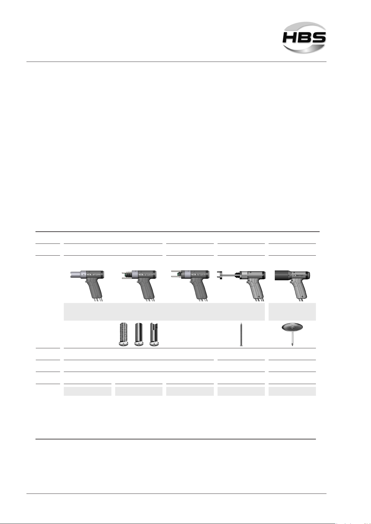
The following stud welding guns are recommended:
Welding
range*) M3 to M6, Ø 2 to 6 mm Ø 2 and 3 mm Ø 2 and 2.7 mm
Stud
length 6 to 40 mm 15 to 55 mm 20 to 280 mm 9.5 to 152.4 mm
C 06-3 C 06-3 C 06-3 C 06-3 CI 03
• Easy handling
• No setting for lift and spring pressure
• Aluminium to M4 (#8)
• Especially suitable
for welding of cupped
head pins (HVCA)
Welding
elements
Welding
process CD (Kontakt)
Stud type CD threaded studs (PT), pins (UT),
Studs with internal thread (IT) CD ISO nails Cupped head pins
Welding
cable 3 m, 25 mm², SK 50 9.3 m, 6 mm², SK 50
Order No. Order No. Order No. Order No. Order No.
92-20-288
(welding gun C 06-3
incl. centering tube
PPR-2)
92-20-275
(welding gun C 06-3
with foot ring and feet)
92-20-275
(welding gun C 06-3
with foot ring and feet))
92-40-010
(distance ring with
screws)
not included in delivery
92-20-275
(welding gun C 06-3
with foot ring and feet)
92-40-043
(ISO leg assembly PSI
with 3-point rest)
not included in delivery
92-20-254
(welding gun CI 03
complete)
*) recommended welding range CDi 502 / welding gun with this equipment

15©HBS Bolzenschweiss-Systeme GmbH & Co. KG
All rights reserved – Reprinting, in whole or in part, only with the approval of the manufacturer
5 Technical Data
5 Technical Data
Stud Welding Unit CDi 502 (with digital display)
for CD stud welding (capacitor discharge welding) according to current standards
Welding range Studs (mild steel, stainless steel):
M3 to M6, dia. 2 to 6 mm
Studs (aluminium): M3 to M4, dia. 3 to 4 mm
Cupped head pins: dia. 2 and 2.7 mm
Welding material Mild steel, stainless steel, aluminium
Welding rate Studs M6 = 10 studs/min. (Charging voltage 95 V)
Cupped head pins dia. 2.7 mm = 10 pins/min.
(Charging voltage 85 V)
Capacity 100 000 µF
Welding time 1 to 3 ms
Charging energy 500 Ws
Charging voltage 50 to 100 V (stepless voltage regulation)
Connection 100 V to 240 V, 50/60 Hz, 10 AT
Power source Capacitor
Cooling method F (temperature controlled cooling fan)
IP Code IP 23 (also permits use outdoors)
Ambient temperature limits 0 °C to 40 °C
Dimension L x W x H 363 x 163 x 257 mm (with handle)
Weight 9.9 kg

©HBS Bolzenschweiss-Systeme GmbH & Co. KG
All rights reserved – Reprinting, in whole or in part, only with the approval of the manufacturer
16
6 Intended Use
6 Intended Use
Our stud welding units are designed and built exclusively for industrial use. Nonin-
dustrial use is expressly forbidden due to the lack of know-how about the welding
technology employed and the applicable standards.
The stud welding unit is intended exclusively for stud welding of standardised wel-
ding elements. Any other use will result in the desired strength of the welded joint
being reduced.
This stud welding unit can only be used with the HBS stud welding guns
– C 06-3 (order no. 92-20-275 or 92-20-288) with ground cable 25 mm2 (order no.
92-40-154) and
– CI 03 (order no. 92-20-254) with ground cable 16 mm2 (order no. 92-40-091).
The intended use also implies observance of the stud welding gun operating manual
and compliance with the intervals and conditions for inspection and maintenance of
the stud welding unit and the components employed.
Always check the operating manual of your stud welding gun whether it may be
used with this stud welding unit.
The stud welding unit must be suitable for welding the welding elements in use.
Welding elements manufactured with the cold formed process have a ange and an
ignition tip. During welding, the ange prevents the arc getting to the cylindric part of
the welding element and increases simultaneously the welding area.
Please refer to the operating manual of your stud welding gun for
detailed information on which welding elements may be used.

17©HBS Bolzenschweiss-Systeme GmbH & Co. KG
All rights reserved – Reprinting, in whole or in part, only with the approval of the manufacturer
7 Warranty
7 Warranty
Please refer to the latest "General Terms and Conditions" for the scope of the
warranty.
The warranty does not cover faults caused by e.g.
– Normal wear,
– Improper handling,
– Failure to observe the operating manual,
– Failure to observe the safety precautions,
– Use for other than the intended purpose, or
– Transport damage.
Warranty entitlement shall no longer be valid if modications, changes or service
and repair work is carried out by unauthorised persons or without the knowledge of
the manufacturer. Invalidation of warranty entitlement shall also render the declara-
tion of conformity invalid. The CE marking shall be declared invalid by the manufac-
turer.
We expressly point out that only spare parts and accessories or components appro-
ved by us may be used. The same applies likewise to installed units from our sub-
suppliers.

©HBS Bolzenschweiss-Systeme GmbH & Co. KG
All rights reserved – Reprinting, in whole or in part, only with the approval of the manufacturer
18
8 Components of the Stud Welding Unit
8 Components of the Stud Welding Unit
The CDi 502 is ideal for use on construction sites:
Protection against internal soiling:
– Internal fan
– Casing without ventilation slots to the
outside
8.1 Main Assemblies
1- Charging device A - Primary supply
2 - Control B - Welding circuit
3 - Welding capacitors
4 - Welding thyristor

19©HBS Bolzenschweiss-Systeme GmbH & Co. KG
All rights reserved – Reprinting, in whole or in part, only with the approval of the manufacturer
8 Components of the Stud Welding Unit
The mains alternating voltage is converted to direct voltage in the charging de-
vice (1). Charging of the welding capacitors (3) is performed with the charging
device and is fully adjustable. The welding capacitors store the energy required for
the welding process. The quantity of energy is dened by the operator via the char-
ging voltage.
The welding thyristor (4) releases the charging voltage.
The charging process and the welding process are controlled by the control sys-
tem (2).
The negative pole of the capacitor is connected to the welding gun. The positive
pole is usually connected to the workpiece via vice grips.
The type plate is located on the backside of the stud welding unit.
Type plate
The type plate contains the following information:
– Manufacturer
– Type
– Order No./Serial No.
– Primary voltage
– Fuse
– Power consumption
– Cooling class
– IP code
– Date

©HBS Bolzenschweiss-Systeme GmbH & Co. KG
All rights reserved – Reprinting, in whole or in part, only with the approval of the manufacturer
20
8 Components of the Stud Welding Unit
8.2 Operation Panel and Display
6 754
1
2 3 1 - Display for charging voltage
2 - Decrease
3 - Increase
4 - Ready
5 - Contact
6 - Trigger
7 - Temperature
The stud welding unit is switched on and off via the mains switch on the rear side.
The charging voltage is indicated on the LED in the display (1):
50 V 75 V 100 V
A sticker on the top of the stud welding unit shows the recommended charging volta-
ge:
M3: 55 V
M4: 65 V
M5: 80 V
M6: 95 V
Use the pushbuttons ( decrease (2) - increase (3)) to set the charging volt-
age of the capacitor battery.
This manual suits for next models
1
Table of contents
Other HBS Welding System manuals


Popular Welding System manuals by other brands


Campbell Hausfeld
Campbell Hausfeld WG3000 Operating instructions & parts manual

Miller Electric
Miller Electric Spectrum 125C owner's manual

JEONGWOOD
JEONGWOOD TSA-500 instruction manual

Hypertherm
Hypertherm Powermax 65 Operator's manual

WeldKing
WeldKing MAG 251 owner's manual

STAMOS
STAMOS S-MULTI 525H UK user manual


