HBX SGL-0600 User manual

HBX Control Systems Inc.
Installation Manual
SGL-0600
Version 1.0.0
SGL-0600
• Single Zone Control

Page 2
Control Systems Inc.
Comfort
Control
Innovation
HBX SGL-0600 Single Zone Control
Version 1.0.0
Table of Contents
TABLE OF CONTENTS
Introduction ............................................................................................ 1-3
Description .............................................................................................. 1
Safety Symbols & Warnings ................................................................... 2
Receipt & Inspection .............................................................................. 2
Technical Data and Dimensions ........................................................... 3
Wiring & Installation ............................................................................... 4-25
Wiring ....................................................................................................... 4
Installation ............................................................................................... 5
Navigating the THM-0600.........................................................................6
Setting the THM-0600................................................................................ 7-19
Application Drawings .............................................................................. 19-20
Warranty Information .............................................................................. 21

HBX SGL-0600 Single Zone Control
Version 1.0.0
Page 1
HBX SGL-0600 SINGLE ZONE MODULE
The HBX Single Zone (SGL-0600) is designed to control
most common HVAC systems and provides exibility
to integrate Heating or cooling systems with multiple
devices including forced air heating and cooling,
inoor heating/cooling, heat pumps, fancoils and
humidier/dehumidier.
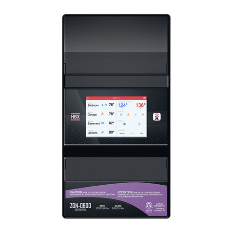
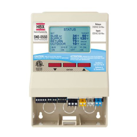
The Single Zone includes a Wi-Fi Enabled Full-Colour
touchscreen thermostat (THM-0600) and relay box
to control your heating and cooling equipment.
The THM-0600 thermostat is a 2 wire (power and
communication) thermostat which makes it ideal for
retrots by re-using the existing 2 wire electrical to
solve the issue of not having enough wires to upgrade
systems.
The single zone relay box allows user to control up to 2
stages of heating and 2 stages cooling with the ability
to control humidity and fan control. The zone box
also allows for 2 dry demand outputs to heating and
cooling devices. Wiring the relay box only requires
24V (low voltage) to power the unit.
This control can also function as a stand alone system
without WiFi capabilities.
FEATURES
• App for Android or Apple Smartphone/tablet
device for remote access with alarm email
notication
• 2 wire communication thermostat
• Humidity and Fan Control
• Up to 2 stage heating and 2 stage cooling
• Two (2) dry demands outputs
• Can be added with the SGL-0600 for additional
fancoil output

HBX SGL-0600 Single Zone Control
Version 1.0.0
Page 2
Extreme Hazard
This action poses a serious threat that could result in
personal injury or death, as well as permanent damage to
the equipment. Proceed with caution.
EXTREME HAZARD: The HBX SGL-0600 is a microprocessor based controller and as such is not to be regarded as a safety (limit)
control. Please consult and install the heating or cooling appliance in accordance with the manufacturer’s recommendations.
Moderate Hazard
This action may cause personal injury or have adverse
effects on the installation process if handled incorrectly.
WARNING: Only suitably qualied individuals with formal training in electrical and hydronic controls should attempt the installation
of this equipment. Incorrect wiring and installation will affect the warranty provided with this unit. Wiring must be completed in
accordance with the codes and practices applicable to the jurisdiction for the actual installation.
WARNING: Non-serviceable product. Send to HBX Controls Inc. only for service.
WARNING: This product can expose you to chemicals including lead, which is known to the State of California to cause cancer
and birth defects or other reproductive harm. For more information go to www.P65Warnings.ca.gov.
WARNING: a) Use copper conductors only if the terminal is acceptable only for connections to copper wire; b) Use aluminum
conductors only or use aluminum or copper-clad aluminum condctors only if the terminal is acceptable only for connection to
aluminum wire; or c) use copper or aluminum conductors or use copper, copper-clad aluminum, or aluminum conductors if the
terminal is acceptable for connection to either copper or aluminum wire.
WARNING: Use only copper conductor supply wire suitable for at least 105 °C
WARNING: All circuits must have a common disconnect and be connected to the same pole of the disconnect.
WARNING: THM-0600 only for use with SGL-0600
Disconnect Power Source
The presence of low voltage(24VAC) or high
voltage(120VAC) could result in personal injury or
permanent damage to components or equipment.
Point of Interest
This point claries pertinent information, or brings your
attention to an action that may have adverse effects on
the installation process.
Drawing Reference
Refer to the specied electrical or mechanical drawing at
the back of the manual.
SAFETY SYMBOLS
SAFETY WARNINGS
RECEIPT & INSPECTION
After receiving, inspect the unit for any possible physical damage that may have occurred during transportation. After unpacking the unit
make sure the box contains:
• 1 x Universal sensor (Part #029-0045)
• 1 x Thermostat THM-0600
• 1 x Thermostat Wall Cutout Template
• 1 x SGL-0600
• 1 x Terminal Screwdriver (2.5 mm)

HBX SGL-0600 Single Zone Control
Version 1.0.0
Page 3
72
2.835
93.60
3.685
38
1.496
39
1.535
120
4.724
100
3.937
Specications:
7 x Triac Outputs 0.500mA max
2 x Dry Contact Demand Relays 24VAC 1A Max
1x Input 24VAC +/- 10% 50/60Hz 2A Max
Combined relay power should not exceed 2A
Weight:
0.220 Kg
Dimensions:
100mm W x 120mm H x 38mm
3.9in W x 4.7in H x 1.5in
ETL Listings:
Meets CSA C22.2 No. 24
Meets UL Standard 873
ETL Control No. 3068143
Storage:
50°F to 104°F (10ºC to 40ºC)
WiFi:
2.4GHz Network Only
FCC ID:
2AHMRESP125
TECHNICAL DATA AND DIMENSIONS
SGL-0600 TECHNICAL DATA
DIMENSIONS

HBX SGL-0600 Single Zone Control
Version 1.0.0
Page 4
WIRING
We recommend all signal wiring to be a minimum of 18AWG shielded wire at a maximum of 500ft.
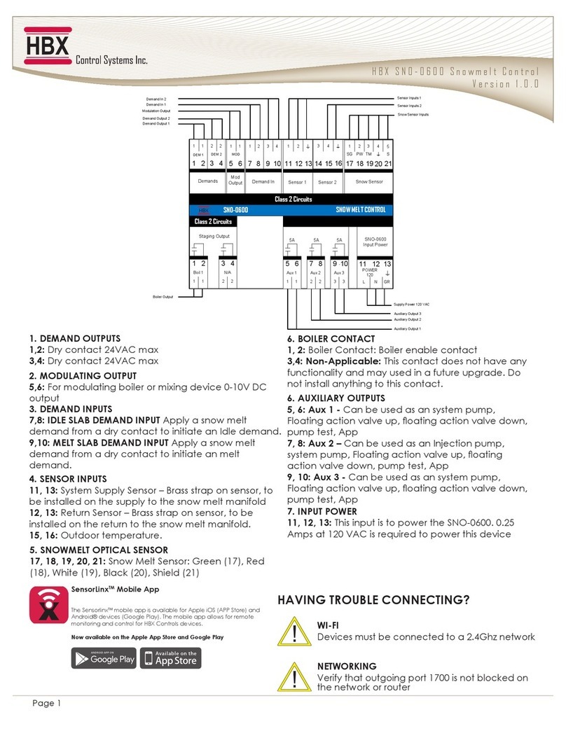
2. DEMAND OUTPUTS
5, 6: Demand 1: closes during calls for either heating or
cooling depending on the Type
7, 8: Demand 2: closes during calls for either heating or
cooling depending on the Type
1. THERMOSTAT INPUTS
1, 2: Input for THM-0600
4. OUTPUTS
1: W1: rst stage heating
2: W2: second stage heating
3: G: Fan control output
5: X: Humidity control output
6: Y1: rst stage cooling
7: Y2: second stage cooling
DO NOT CONNECT
POWER HERE
1A
7
DEM 2
8 7
8 5
DEM 1
6 5
6
1A
SGL-0600 Zone Control
8
78
7
6
C
910
R
+
MOD
4 3
-
THM
Input
Class 2 Circuits
5
45
4
3
3
2
2
1
Outputs
1
X D G W1
24V AC
TH1
THM
2 1
GND
MOD
Output
Demand Outputs
HBX
Class 2 Circuits
6
Y1Y2RC W2
Input Power
THM-0600 Input
First Stage Heating Output
Fancoil Heating Output
Fan Control Output
Humidity Output
First Stage Cooling Output
Fancoil Cooling Output
Input
Demand 1 Output
Demand 2 Output
WIRING AND INSTALLATION
3. INPUTS
8: RC: 24VAC input for Y1 and Y2
9, 10: R,C: input power for SGL-0600 and 24VAC input for W1,
W2, G and X.

HBX SGL-0600 Single Zone Control
Version 1.0.0
Page 5
SGL-0600 Installation
The SGL-0600 is designed to be wall mounted or installed in a separate electrical enclosure. The unit should be
installed indoors and protected from falling water and high humidity conditions. With all the covers in place, it is
designed to protect any individual from accidental electrical shock. It is not suitable for installation in hazardous
locations and should not be close to any electromagnetic elds.
• Identify the four mounting holes on the SGL-0600, mark on the wall the desired location of mounting
• Pre-drill, anchor and fasten the two bottom screws for mounting
• Hang SGL-0600 and fasten the top two screws then tighten the bottom screws
• Complete wiring connections in accordance with local area electrical codes
Thermostat eld signal wiring installation
The signal wiring that connects the SGL-0600 to each thermostat should not run parallel for any lengths with
any other wires. If this is a retrot installation and the thermostat signal wiring installation can not be veried it is
recommended that the thermostats to be installed in the mechanical room with remote room (029-0022, not
provided) and/or oor sensors (029-0045).
INSTALLATION
Wiring polarity is important. Match the ground
and TH on the THM-0600 to the SGL-0600 control.
The THM-0600 is the only approved
thermostat to be used with the SGL-0600.
Do not supply external power to the
thermostat.
In order to assure proper room temperature, it
is important to identify the ideal location of the
thermostat. It should be approximately 5 feet from
the oor and at least 1 foot from door openings on
an interior wall. Avoid exposing the thermostat to
direct sunlight, to air ows (doors, windows, etc.) as
well as to heat sources. Ensure the cavity that the
thermostat will be installed in is well insulated.
1 2 3 4
1 - 2: External Room Sensor
3 - 4: Aux Sensor
TH: Communication
& Power from
ZON-0600
Use a screwdriver to gently pop the front cover
off from the top of the thermostat, and then
remove the front to expose wiring terminals.
Do not use the screwdriver on the bottom of
the thermostat. This can cause damage to the
THM-0600
External Room Thermistor
On the THM-0600, the room thermistor switch is located on the bottom left
corner of the thermostat.
Toggling this switch will allow the user to alternate between the built in room
thermistor on the THM-0600, or an external room thermistor connected to pins
1 and 2 on the THM-0600.
INTERNAL ROOM
EXTERNAL ROOM

HBX SGL-0600 Single Zone Control
Version 1.0.0
Page 6
PROGRAMMING THM-0600
Navigating the Thermostat
The touchscreen of this thermostat makes it easy to change used settings. Touch any
item to adjust its setting excluding the time on the home screen.
Simply touch the temperature to adjust your desired target temperature. Pressing the
menu icon on top right corner allows you to view the main “Setup Menu” options.
Pressing the back icon allows you to return to the home screen or setup menu.
Touching the area below the current temperature allows you to see what current
demands are present.
ZONE 1
LIVING ROOM
Floor
75°F
Target
74°F
72.0
°F
Humidity
30%
10:00am Outdoor
47°F
Special Functions
Stat Type
Demand Type
Priority
THM Mode
Aux Sensor
Room Offset
ATHM-0123
Heat Only
Low
None
Air
None
0°
Setting the Thermostat
Special Functions
Enter the “Special Functions” screen by touching and holding down the
menu icon for 5 seconds (from the status screen). To select the desired option, simply
touch any item to adjust it’s setting.
Unlock Thermostat
Repeat the same process as locking the thermostat. Press and hold the time (clock)
on the top left corner on the main screen for 20 seconds. The lock icon on the
screen will go away.
Zone 1
LIVING ROOM
Floor
70°
F
Target
72°
F
72.0
°F
10:00
am
Outdoor
47°F
Zone 1
LIVING ROOM
Floor
70°
F
Target
72°
F
72.0
°F
10:00
am
Outdoor
47°F
Zone 1
LIVING ROOM
Floor
70°
F
Target
72°
F
72
.0
°F
10:00
am
Outdoor
47°
F
Zone 1
LIVING ROOM
Floor
70°
F
Target
72°
F
72
.0
°F
10:00
am
Outdoor
47°
F
No settings will be able to be changed when the thermostat is locked. Only on the Thermolinx mobile app you will
have the ability to still make changes. When the Thermostat is locked, only minimal temperature target adjustment
can be made. 2°C/3°F above/under.
Lockout Thermostat
On the main screen press and hold the time (clock) for 20 seconds. The lock icon
will appear in the top right corner.
Sync Code
This number is the identier used in the HBX ThermoLinx App to connect to
your thermostat.

HBX SGL-0600 Single Zone Control
Version 1.0.0
Page 7
2 Stage Heat Function
Select the “2 Stage Heat Function” for applications using 2 stage heating. This type will turn
on W1, W2 and Demand 1 and 2.
Heat Only Function
Select the “Heat Only Function” for applications using a single heating source. This type will
turn on W1 and Demand 1 and 2.
Special Functions
ATHM-0000
Stat Type
Demand Type
Priority
THM Mode
Aux Sensor
Room Offset
Fancoil Setup
Heat Only
Low
None
Air
Floor
0°
Special Functions
ATHM-0000
Stat Type
Demand Type
Priority
THM Mode
Aux Sensor
Room Offset
Fancoil Setup
Cool Only
Low
None
Air
Floor
0°
Special Functions
ATHM-0000
Stat Type
Demand Type
Priority
THM Mode
Aux Sensor
Room Offset
Fancoil Setup
Heat and Cool
Low
None
Air
Floor
0°
Special Functions
ATHM-0000
Stat Type
Demand Type
Priority
THM Mode
Aux Sensor
Room Offset
Fancoil Setup
2 Stage Heat
Low
None
Air
Floor
0°
Special Functions
ATHM-0000
Stat Type
Demand Type
Priority
THM Mode
Aux Sensor
Room Offset
Fancoil Setup
2 Stage Cool
Low
None
Air
Floor
0°
Special Functions
ATHM-0000
Stat Type
Demand Type
Priority
THM Mode
Aux Sensor
Room Offset
Fancoil Setup
2 Heat with Cool
Low
None
Air
Floor
0°
Special Functions
ATHM-0000
Stat Type
Demand Type
Priority
THM Mode
Aux Sensor
Room Offset
Fancoil Setup
2 Cool with Heat
Low
None
Air
Floor
0°
Special Functions
ATHM-0000
Stat Type
Demand Type
Priority
THM Mode
Aux Sensor
Room Offset
Fancoil Setup
2 Heat and 2 Cool
Low
None
Air
Floor
0°
Special Functions
ATHM-0000
Stat Type
Demand Type
Priority
THM Mode
Aux Sensor
Room Offset
Fancoil Setup
Heat Only
Low
None
Air
Floor
0°
Special Functions
ATHM-0000
Stat Type
Demand Type
Priority
THM Mode
Aux Sensor
Room Offset
Fancoil Setup
Cool Only
Low
None
Air
Floor
0°
Special Functions
ATHM-0000
Stat Type
Demand Type
Priority
THM Mode
Aux Sensor
Room Offset
Fancoil Setup
Heat and Cool
Low
None
Air
Floor
0°
Special Functions
ATHM-0000
Stat Type
Demand Type
Priority
THM Mode
Aux Sensor
Room Offset
Fancoil Setup
2 Stage Heat
Low
None
Air
Floor
0°
Special Functions
ATHM-0000
Stat Type
Demand Type
Priority
THM Mode
Aux Sensor
Room Offset
Fancoil Setup
2 Stage Cool
Low
None
Air
Floor
0°
Special Functions
ATHM-0000
Stat Type
Demand Type
Priority
THM Mode
Aux Sensor
Room Offset
Fancoil Setup
2 Heat with Cool
Low
None
Air
Floor
0°
Special Functions
ATHM-0000
Stat Type
Demand Type
Priority
THM Mode
Aux Sensor
Room Offset
Fancoil Setup
2 Cool with Heat
Low
None
Air
Floor
0°
Special Functions
ATHM-0000
Stat Type
Demand Type
Priority
THM Mode
Aux Sensor
Room Offset
Fancoil Setup
2 Heat and 2 Cool
Low
None
Air
Floor
0°
Cool Only Function
Select the “Cool Only Function” for applications using a single cooling source. This type will
turn on Y1 and Demand 1 and 2.
Heat and Cool Function
Select the “Heat and Cool Function” for applications using a single heating source and a
single cooling source. This type will turn on W1 and Demand 1 for heat and Y2 Demand 2 for
cool.
2 Stage Cool Function
Select the “2 Stage Cool Function” for applications using 2 stage cooling. This type will turn
on Y1, Y2 and Demand 1 and 2.
Type - Select between Heating, Cooling, and a variety of combined modes.

HBX SGL-0600 Single Zone Control
Version 1.0.0
Page 8
Low - Low Temperature Demand
High - High Temperature Demand
DHW - Domestic Hot Water (Digital Aquastat)
Fancoil - Fancoil Demand
Note: DHW only available in heat only type
Demand - This option allows the user to determine what happens when the thermostat makes a call.
2 Heat with Cool Function
Select the “2 Heat with Cool Function” for applications using 2 stage heating and 1 stage
cooling. This type will turn on W1, W2 and Demand 1 for heat and Y2 and Demand 2 for
cool.
2 Cool with Heat Function
Select the “2 Cool with Heat Function” for applications using 2 stage cooling and 1 stage
heating. This type will turn on Y1, Y2 and Demand 2 for cool and W1 and Demand 1 for heat.
2 Heat and 2 Cool Function
Select the “2 Heat and 2 Cool Function” for applications using 2 stage heating and 2 stage
cooling. This type will turn on W1, W2 and Demand 1 for heat and Y1, Y2 and Demand 2 for
cool.
Special Functions
ATHM-0000
Stat Type
Demand Type
Priority
THM Mode
Aux Sensor
Room Offset
Fancoil Setup
Heat Only
Low
None
Air
Floor
0°
Special Functions
ATHM-0000
Stat Type
Demand Type
Priority
THM Mode
Aux Sensor
Room Offset
Fancoil Setup
Cool Only
Low
None
Air
Floor
0°
Special Functions
ATHM-0000
Stat Type
Demand Type
Priority
THM Mode
Aux Sensor
Room Offset
Fancoil Setup
Heat and Cool
Low
None
Air
Floor
0°
Special Functions
ATHM-0000
Stat Type
Demand Type
Priority
THM Mode
Aux Sensor
Room Offset
Fancoil Setup
2 Stage Heat
Low
None
Air
Floor
0°
Special Functions
ATHM-0000
Stat Type
Demand Type
Priority
THM Mode
Aux Sensor
Room Offset
Fancoil Setup
2 Stage Cool
Low
None
Air
Floor
0°
Special Functions
ATHM-0000
Stat Type
Demand Type
Priority
THM Mode
Aux Sensor
Room Offset
Fancoil Setup
2 Heat with Cool
Low
None
Air
Floor
0°
Special Functions
ATHM-0000
Stat Type
Demand Type
Priority
THM Mode
Aux Sensor
Room Offset
Fancoil Setup
2 Cool with Heat
Low
None
Air
Floor
0°
Special Functions
ATHM-0000
Stat Type
Demand Type
Priority
THM Mode
Aux Sensor
Room Offset
Fancoil Setup
2 Heat and 2 Cool
Low
None
Air
Floor
0°
Special Functions
ATHM-0000
Stat Type
Demand Type
Priority
THM Mode
Aux Sensor
Room Offset
Fancoil Setup
Heat Only
Low
None
Air
Floor
0°

HBX SGL-0600 Single Zone Control
Version 1.0.0
Page 9
The Priority Shield option allows a zone to ignore other priorities from other zones.
A priority set to none will have no priority and will be overridden by all other zone priorities.
Priority 1 is a timed priority of 60 minutes, generally used for DHW.
Priority - This option allows the user to set a priority on a zone(s) over other zone(s). Priorities range from 1 (highest) to 7
(lowest). Higher priorities will lock out lower priorities until the demand has been satised. Multiple zones can be given the
same numbered priority.
Mode - This option allows you to select between Air, Floor and Dual sensor modes
Air
Thermistor within the thermostat sensing temperature providing feedback for the specic
room or zone being controlled by the thermostat
Floor
Sensor temperature providing feedback from the oor surface to the thermostat. This
mode will run the thermostat on oor temperature only. Aux sensor will automatically be
set to oor.
Only available when heating modes are the primary function. Must have oor
sensor connected.
Floor Mode: Differential
When in oor mode, the differential option is set to allow a differential around the target to
reduce the chances of short cycling. Ex. A differential of 4°F is 2°F above the setpoint and
2°F below the setpoint.
Ex. A differential of 4°F is 2°F above the setpoint and 2°F below the setpoint.
Special Functions
ATHM-0000
Stat Type
Demand Type
Priority
THM Mode
Aux Sensor
Room Offset
Fancoil Setup
Heat Only
Low
None
Air
Floor
0°
Special Functions
ATHM-0000
THM Mode
Aux Sensor
Room Offset
Fancoil Setup
4-Pipe Geo
Room Name Setup
Default Setup
Air
Floor
0°
OFF
Special Functions
ATHM-0000
THM Mode
Aux Sensor
Differential
Room Offset
Fancoil Setup
4-Pipe Geo
Room Name Setup
Default Setup
Floor
Floor
6°
0°
OFF
Special Functions
ATHM-0000
THM Mode
Aux Sensor
Floor Min
Floor Max
Room Offset
Fancoil Setup
4-Pipe Geo
Dual
Floor
70°
80°
-20°
OFF
Special Functions
ATHM-0000
THM Mode
Aux Sensor
Room Offset
Fancoil Setup
4-Pipe Geo
Room Name Setup
Default Setup
Air
Floor
0°
OFF
Special Functions
ATHM-0000
THM Mode
Aux Sensor
Differential
Room Offset
Fancoil Setup
4-Pipe Geo
Room Name Setup
Default Setup
Floor
Floor
6°
0°
OFF
Special Functions
ATHM-0000
THM Mode
Aux Sensor
Floor Min
Floor Max
Room Offset
Fancoil Setup
4-Pipe Geo
Dual
Floor
70°
80°
-20°
OFF

HBX SGL-0600 Single Zone Control
Version 1.0.0
Page 10
Dual
Sensor temperature providing feedback for both the air temperature and oor sensor
temperatures. Aux sensor will automatically be set to oor
Only available when heating modes are the primary function. Must have oor
sensor connected.
When using the external room/oor sensor on pins 1 and 2 ensure the
dipswitch is set to external.
Dual Mode: Floor Min/Max
Floor Max - The thermostat will not allow the oor temperature to go above this value,
protecting the integrity of the oor covering.
Floor Min - The thermostat will not allow the oor temperature to go below this value
None – No external thermistor attached.
Floor – Displays the oor temperature using external 1 sensor
Room - Disregards internal sensor, uses external
Outdoor – Uses external sensor to display outdoor temperature
RM/Ave – Averages auxiliary sensor and internal sensor, or optional external room sensor
Floor Ave – Averages auxiliary and optional external oor sensor in lieu of room sensor
Aux Sensor - Auxiliary thermistor
Special Functions
ATHM-0000
THM Mode
Aux Sensor
Room Offset
Fancoil Setup
4-Pipe Geo
Room Name Setup
Default Setup
Air
Floor
0°
OFF
Special Functions
ATHM-0000
THM Mode
Aux Sensor
Differential
Room Offset
Fancoil Setup
4-Pipe Geo
Room Name Setup
Default Setup
Floor
Floor
6°
0°
OFF
Special Functions
ATHM-0000
THM Mode
Aux Sensor
Floor Min
Floor Max
Room Offset
Fancoil Setup
4-Pipe Geo
Dual
Floor
70°
80°
-20°
OFF
Special Functions
ATHM-0000
THM Mode
Aux Sensor
Room Offset
Fancoil Setup
4-Pipe Geo
Room Name Setup
Default Setup
Air
Floor
0°
OFF
Special Functions
ATHM-0000
THM Mode
Aux Sensor
Differential
Room Offset
Fancoil Setup
4-Pipe Geo
Room Name Setup
Default Setup
Floor
Floor
6°
0°
OFF
Special Functions
ATHM-0000
THM Mode
Aux Sensor
Floor Min
Floor Max
Room Offset
Fancoil Setup
4-Pipe Geo
Dual
Floor
70°
80°
-20°
OFF
Special Functions
ATHM-0000
Stat Type
Demand Type
Priority
THM Mode
Aux Sensor
Room Offset
Fancoil Setup
Heat Only
Low
None
Air
Floor
0°

HBX SGL-0600 Single Zone Control
Version 1.0.0
Page 11
Example Actual Room Temperature 72 °F.
Direct Sunlight causes Thermostat to show 78 °F.
The user can put an offset of -6 °F to get the temperatures to match.
Minimum value -20°F
Maximum value 20°F
If you are utilizing a fancoil, you will have access to the following settings:
Fan On Demand
Zone On Demand
Temperature Averaging
Fan Mode
Damper Mode
Fancoil Setup: Fan On Demand
This option will turn the fan on with any fancoil demand.
Room Offset - This feature allows you to program an offset. In the case that the thermostat is not reading the same tem-
perature as the actual temperature in the room.
Fancoil Setup - This setting takes you to the Fancoil Setup Menu.
Special Functions
ATHM-0000
Stat Type
Demand Type
Priority
THM Mode
Aux Sensor
Room Offset
Fancoil Setup
Heat Only
Low
None
Air
Floor
0°
Special Functions
ATHM-0000
THM Mode
Aux Sensor
Room Offset
Fancoil Setup
4-Pipe Geo
Default Setup
Password
Air
Floor
0°
OFF
Fancoil Setup
Fan ON Demand
Zone ON Demand
Temp Average
Stage Delay
Damper Mode
OFF
OFF
None
15 mins
OFF
Fancoil Setup
Fan ON Demand
Zone ON Demand
Temp Average
Stage Delay
Damper Mode
OFF
OFF
None
15 mins
OFF
Fancoil Setup
Fan ON Demand
Zone ON Demand
Temp Average
Stage Delay
Damper Mode
OFF
OFF
None
15 mins
OFF
Fancoil Setup
Fan ON Demand
Zone ON Demand
Temp Average
Stage Delay
Damper Mode
OFF
OFF
None
15 mins
OFF
Fancoil Setup
Fan ON Demand
Zone ON Demand
Temp Average
Stage Delay
Damper Mode
OFF
OFF
None
15 mins
OFF
Special Functions
ATHM-0000
THM Mode
Aux Sensor
Room Offset
Fancoil Setup
4-Pipe Geo
Default Setup
Password
Air
Floor
0°
OFF
Fancoil Setup
Fan ON Demand
Stage Delay
OFF
15 mins
Fancoil Setup
Fan ON Demand
Zone ON Demand
Temp Average
Stage Delay
Damper Mode
OFF
OFF
None
15 mins
OFF
Fancoil Setup
Fan ON Demand
Zone ON Demand
Temp Average
Stage Delay
Damper Mode
OFF
OFF
None
15 mins
OFF
Fancoil Setup
Fan ON Demand
Stage Delay
OFF
15 mins
Fancoil Setup
Fan ON Demand
Zone ON Demand
Temp Average
Stage Delay
Damper Mode
OFF
OFF
None
15 mins
OFF
Fancoil Setup: Stage Delay
Use this setting to adjust the lagtime between stage 1 and stage 2. This option is only avail-
able when 2 heating or cooling stages are selected.
Default - 15m
Range - 1m - 240m
Special Functions
ATHM-0000
THM Mode
Aux Sensor
Room Offset
Fancoil Setup
4-Pipe Geo
Default Setup
Password
Air
Floor
0°
OFF
Fancoil Setup
Fan ON Demand
Stage Delay
OFF
15 mins
Fancoil Setup
Fan ON Demand
Zone ON Demand
Temp Average
Stage Delay
Damper Mode
OFF
OFF
None
15 mins
OFF
Fancoil Setup
Fan ON Demand
Zone ON Demand
Temp Average
Stage Delay
Damper Mode
OFF
OFF
None
15 mins
OFF
Fancoil Setup
Fan ON Demand
Stage Delay
OFF
15 mins
Fancoil Setup
Fan ON Demand
Zone ON Demand
Temp Average
Stage Delay
Damper Mode
OFF
OFF
None
15 mins
OFF

HBX SGL-0600 Single Zone Control
Version 1.0.0
Page 12
Save Current Settings - This option will save the current settings in the event the settings
get changed in the future.
Load Current Settings - This options will load the last saved current settings.
Factory Reset - Reset all settings back to default.
Room Number - sets the number associated with the name. Range 0-9
Name - sets the name of the thermostat. Kitchen, Living Room, Bathroom, Bedroom, Base-
ment, Guest Room, Main Floor, Ofce, Upstairs, DHW Tank.
Press To Save Name - once the number and name is set hit this option to save the infor-
mation.
Default Setup - Restores the thermostat to factory default settings or previously saved settings.
Special Functions
ATHM-0000
THM Mode
Aux Sensor
Room Offset
Fancoil Setup
4-Pipe Geo
Default Setup
Password
Air
Floor
0°
OFF
Special Functions
ATHM-0000
Stat Type
Demand Type
Priority
THM Mode
Aux Sensor
Room Offset
Room Name Setup
Heat Only
Low
None
Air
Floor
0°
Room Name Setup - This menu allows for the option to select preset names for the THM-0600.

HBX SGL-0600 Single Zone Control
Version 1.0.0
Page 13
Setup Menu
Enter the “Setup Menu” screen by touching the menu icon. To select the desired option, simply touch any item to adjust
it’s setting.
OFF - Disables scheduling
ON - Enables scheduling
Weekday Settings (Monday to Friday) - Adjust four time periods within the weekday
program menu.
Weekend Settings (Saturday to Sunday) - Adjust four time periods within the weekend
program menu.
Setting a schedule
Time - Select the time for the schedule to be started by pressing the time on the desired
schedule event.
Cooling Temperature (Blue) - Select the cooling temperature and adjust accordingly for
each schedule event.
Heating Temperature (Red) - Select the heating temperature and adjust accordingly for
each schedule event.
Setup Menu
Schedules
Weekday Settings
Weekend Settings
Mode
Away Settings
Humidity
Humidity Settings
ON
Heat
OFF
ON
Setup Menu
Schedules
Weekday Settings
Weekend Settings
Mode
Away Settings
Humidity
Humidity Settings
ON
Heat
OFF
ON
Weekday
6:00am
8:00am
4:00pm
10:00pm
70°
66°
72°
64°
Weekday
6:00am
8:00am
4:00pm
10:00pm
70°
66°
72°
64°
Weekday
6:00am
8:00am
4:00pm
10:00pm
70°
66°
72°
64°
Weekend
6:00am
8:00am
4:00pm
10:00pm
70°
66°
72°
64°
Time
8:00am
Heating
70
Weekend
6:00am
8:00am
4:00pm
10:00pm
70°
66°
72°
64°
Time
8:00am
Weekend
6:00am
8:00am
4:00pm
10:00pm
70°
66°
72°
64°
Heating
70
Weekend
6:00am
8:00am
4:00pm
10:00pm
70°
66°
72°
64°
70°
66°
72°
64°
Heating
70
Schedules - Allows themostat temperatures to be scheduled up to 4 time periods for weekdays and weekends.
Heating/Cooling temperatures will only be displayed if thermostat has a heating/cooling type selected.
The cooling setting must be a minimum of 2°F (or 1°C) higher than the heating setting.
Setup Menu
Schedules
Weekday Settings
Weekend Settings
Mode
Away Settings
Humidity
Humidity Settings
ON
Heat
OFF
ON
Setup Menu
Schedules
Weekday Settings
Weekend Settings
Mode
Away Settings
Humidity
Humidity Settings
ON
Heat
OFF
ON
Weekday
6:00am
8:00am
4:00pm
10:00pm
70°
66°
72°
64°
Weekday
6:00am
8:00am
4:00pm
10:00pm
70°
66°
72°
64°
Weekday
6:00am
8:00am
4:00pm
10:00pm
70°
66°
72°
64°
Weekend
6:00am
8:00am
4:00pm
10:00pm
70°
66°
72°
64°
Time
8:00am
Heating
70
Weekend
6:00am
8:00am
4:00pm
10:00pm
70°
66°
72°
64°
Time
8:00am
Weekend
6:00am
8:00am
4:00pm
10:00pm
70°
66°
72°
64°
Heating
70
Weekend
6:00am
8:00am
4:00pm
10:00pm
70°
66°
72°
64°
70°
66°
72°
64°
Heating
70
Setup Menu
Schedules
Weekday Settings
Weekend Settings
Mode
Away Settings
Humidity
Humidity Settings
ON
Heat
OFF
ON
Setup Menu
Schedules
Weekday Settings
Weekend Settings
Mode
Away Settings
Humidity
Humidity Settings
ON
Heat
OFF
ON
Weekday
6:00am
8:00am
4:00pm
10:00pm
70°
66°
72°
64°
Weekday
6:00am
8:00am
4:00pm
10:00pm
70°
66°
72°
64°
Weekday
6:00am
8:00am
4:00pm
10:00pm
70°
66°
72°
64°
Weekend
6:00am
8:00am
4:00pm
10:00pm
70°
66°
72°
64°
Time
8:00am
Heating
70
Weekend
6:00am
8:00am
4:00pm
10:00pm
70°
66°
72°
64°
Time
8:00am
Weekend
6:00am
8:00am
4:00pm
10:00pm
70°
66°
72°
64°
Heating
70
Weekend
6:00am
8:00am
4:00pm
10:00pm
70°
66°
72°
64°
70°
66°
72°
64°
Heating
70

HBX SGL-0600 Single Zone Control
Version 1.0.0
Page 14
Heating Target - Change the minimum temperature for your zone. If the temperature in the
zone falls below this temperature, heating will come on.
Cooling Target - Change the maximum temperature for your zone. If the temperature in
the zone increases above this temperature, cooling will come on.
Auto - The thermostat maintains cooling and heating as needed
Heat - Overrides the thermostat to heat only mode
Cool - Overrides the thermostat to cool only mode
Off - Disable heating and cooling on the thermostat
Heat Target - This allows the end user to select a heat target when away mode is enabled.
Cool Target - This allows the end user to select a cool target when away mode is enabled.
Heating/Cooling Target - The chosen setpoint for heating and cooling zones. Targets will be accessible in relation to the
thermostat type chosen.
Mode - This option allows setting of the thermostat mode to auto, heat, cool or off.
Away Settings - Set the temperature for when the zone is in Away Mode. Away mode will override the schedule to a
lower/higher temperature.
This feature is unavailable if schedules are enabled.
Away heat target must never exceed thermostat target. Away cool target
must never be below thermostat target.
Setup Menu
Schedules
Weekday Settings
Weekend Settings
Mode
Away Settings
Humidity
Humidity Settings
ON
Heat
OFF
ON
Setup Menu
Schedules
Weekday Settings
Weekend Settings
Mode
Away Settings
Humidity
Humidity Settings
ON
Heat
OFF
ON
Setup Menu
Schedules
Weekday Settings
Weekend Settings
Mode
Away Settings
Humidity
Humidity Settings
ON
Heat
OFF
ON
Setup Menu
Schedules
Weekday Settings
Weekend Settings
Mode
Away Settings
Humidity
Humidity Settings
ON
Heat
OFF
ON
Mode
Away Settings
Humidity
Humidity Settings
Fan Settings
Backlight
Degrees
Heat
OFF
ON
Bright
°F
Setup Menu
Mode
Away Settings
Humidity
Humidity Settings
Fan Settings
Backlight
Degrees
Heat
OFF
ON
Bright
°F
Setup Menu
Mode
Away Settings
Humidity
Humidity Settings
Fan Settings
Backlight
Degrees
Heat
OFF
ON
Bright
°F
Setup Menu
Setup Menu
Schedules
Weekday Settings
Weekend Settings
Mode
Away Settings
Humidity
Humidity Settings
ON
Heat
OFF
ON
Setup Menu
Schedules
Weekday Settings
Weekend Settings
Mode
Away Settings
Humidity
Humidity Settings
ON
Heat
OFF
ON
Setup Menu
Schedules
Weekday Settings
Weekend Settings
Mode
Away Settings
Humidity
Humidity Settings
ON
Heat
OFF
ON
Setup Menu
Schedules
Weekday Settings
Weekend Settings
Mode
Away Settings
Humidity
Humidity Settings
ON
Heat
OFF
ON
Mode
Away Settings
Humidity
Humidity Settings
Fan Settings
Backlight
Degrees
Heat
OFF
ON
Bright
°F
Setup Menu
Mode
Away Settings
Humidity
Humidity Settings
Fan Settings
Backlight
Degrees
Heat
OFF
ON
Bright
°F
Setup Menu
Mode
Away Settings
Humidity
Humidity Settings
Fan Settings
Backlight
Degrees
Heat
OFF
ON
Bright
°F
Setup Menu
Setup Menu
Schedules
Weekday Settings
Weekend Settings
Mode
Away Settings
Humidity
Humidity Settings
ON
Heat
OFF
ON
Setup Menu
Schedules
Weekday Settings
Weekend Settings
Mode
Away Settings
Humidity
Humidity Settings
ON
Heat
OFF
ON
Weekday
6:00am
8:00am
4:00pm
10:00pm
70°
66°
72°
64°
Weekday
6:00am
8:00am
4:00pm
10:00pm
70°
66°
72°
64°
Weekday
6:00am
8:00am
4:00pm
10:00pm
70°
66°
72°
64°
Weekend
6:00am
8:00am
4:00pm
10:00pm
70°
66°
72°
64°
Time
8:00am
Heating
70
Weekend
6:00am
8:00am
4:00pm
10:00pm
70°
66°
72°
64°
Time
8:00am
Weekend
6:00am
8:00am
4:00pm
10:00pm
70°
66°
72°
64°
Heating
70
Weekend
6:00am
8:00am
4:00pm
10:00pm
70°
66°
72°
64°
70°
66°
72°
64°
Heating
70

HBX SGL-0600 Single Zone Control
Version 1.0.0
Page 15
Fan w/ Humidity - This option will turn on your fan when there is a humidity demand.
Target - When humidity is set to ON, use this setting to manually adjust your humidity target.
Type - This option allows you to set the thermostat to humidify or dehumidify.
Fan Settings: Fan Mode
OFF - Fan is off
ON - Enables the fan to run constantly, regardless of whether the thermostat is calling for
heating or cooling
INT - This setting will set the ON/OFF time for the intermittent fan
Ex: The fan will come on for 15 min every 2H. Set (Int Fan On: 15 min) & (Int Fan Off: 2H)
Auto Time - When connected to a 2.4 GHz Network the time displayed on the THM-0600’s
will be associated with the time zone you have chosen.
Time - EManual time input (24 hour clock)
Day of the Week - Manual day input (Mon, Tue, Wed, Thu, Fri, Sat, Sun)
Timezone - Select the time zone for your area.
Humidity Settings - Congure humidity settings on the thermostat.
Fan Settings - Enable or disable fan settings on the thermostat.
Time Settings
Setup Menu
Schedules
Weekday Settings
Weekend Settings
Mode
Away Settings
Humidity
Humidity Settings
ON
Heat
OFF
ON
Setup Menu
Schedules
Weekday Settings
Weekend Settings
Mode
Away Settings
Humidity
Humidity Settings
ON
Heat
OFF
ON
Setup Menu
Schedules
Weekday Settings
Weekend Settings
Mode
Away Settings
Humidity
Humidity Settings
ON
Heat
OFF
ON
Setup Menu
Schedules
Weekday Settings
Weekend Settings
Mode
Away Settings
Humidity
Humidity Settings
ON
Heat
OFF
ON
Mode
Away Settings
Humidity
Humidity Settings
Fan Settings
Backlight
Degrees
Heat
OFF
ON
Bright
°F
Setup Menu
Mode
Away Settings
Humidity
Humidity Settings
Fan Settings
Backlight
Degrees
Heat
OFF
ON
Bright
°F
Setup Menu
Mode
Away Settings
Humidity
Humidity Settings
Fan Settings
Backlight
Degrees
Heat
OFF
ON
Bright
°F
Setup Menu
Setup Menu
Schedules
Weekday Settings
Weekend Settings
Mode
Away Settings
Humidity
Humidity Settings
ON
Heat
OFF
ON
Setup Menu
Schedules
Weekday Settings
Weekend Settings
Mode
Away Settings
Humidity
Humidity Settings
ON
Heat
OFF
ON
Setup Menu
Schedules
Weekday Settings
Weekend Settings
Mode
Away Settings
Humidity
Humidity Settings
ON
Heat
OFF
ON
Setup Menu
Schedules
Weekday Settings
Weekend Settings
Mode
Away Settings
Humidity
Humidity Settings
ON
Heat
OFF
ON
Mode
Away Settings
Humidity
Humidity Settings
Fan Settings
Backlight
Degrees
Heat
OFF
ON
Bright
°F
Setup Menu
Mode
Away Settings
Humidity
Humidity Settings
Fan Settings
Backlight
Degrees
Heat
OFF
ON
Bright
°F
Setup Menu
Mode
Away Settings
Humidity
Humidity Settings
Fan Settings
Backlight
Degrees
Heat
OFF
ON
Bright
°F
Setup Menu
Humidity
Humidity Settings
Fan Settings
Time Settings
WiFi Settings
Backlight
Degrees
ON
Bright
°F
Setup Menu
STANDARD TIMEZONES
Atlantic
Standard Time AST GMT-4
Eastern
Standard Time EST GMT-5
Central
Standard Time CST GMT-6
Mountain
Standard Time MST GMT-7
Pacic Standard
Time PST GMT-8
Alaskan
Standard Time AST GMT-9
Hawaiian
Standard Time HST GMT-10
DAYLIGHT SAVINGS
Atlantic Daylight
Time ADT GMT-3
Eastern Daylight
Time EDT GMT-4
Central Daylight
Time CDT GMT-5
Mountain
Daylight Time MDT GMT-6
Pacic Daylight
Time PDT GMT-7

HBX SGL-0600 Single Zone Control
Version 1.0.0
Page 16
OFF - Screen backlight is off during idle
BRIGHT - Screen backlight is at 100%
DIM - Screen backlight is at 50%
°C - Display temperatures in Celcius
°F - Display temperatures in Farenheit
Backlight - This option adjusts the brightness of the thermostat screen during idle.
Degrees - This option will change the thermostat temperature to either Celsius (°C) or Farenheit (°F).
Setup Menu
Schedules
Weekday Settings
Weekend Settings
Mode
Away Settings
Humidity
Humidity Settings
ON
Heat
OFF
ON
Setup Menu
Schedules
Weekday Settings
Weekend Settings
Mode
Away Settings
Humidity
Humidity Settings
ON
Heat
OFF
ON
Setup Menu
Schedules
Weekday Settings
Weekend Settings
Mode
Away Settings
Humidity
Humidity Settings
ON
Heat
OFF
ON
Setup Menu
Schedules
Weekday Settings
Weekend Settings
Mode
Away Settings
Humidity
Humidity Settings
ON
Heat
OFF
ON
Mode
Away Settings
Humidity
Humidity Settings
Fan Settings
Backlight
Degrees
Heat
OFF
ON
Bright
°F
Setup Menu
Mode
Away Settings
Humidity
Humidity Settings
Fan Settings
Backlight
Degrees
Heat
OFF
ON
Bright
°F
Setup Menu
Mode
Away Settings
Humidity
Humidity Settings
Fan Settings
Backlight
Degrees
Heat
OFF
ON
Bright
°F
Setup Menu
Setup Menu
Schedules
Weekday Settings
Weekend Settings
Mode
Away Settings
Humidity
Humidity Settings
ON
Heat
OFF
ON
Setup Menu
Schedules
Weekday Settings
Weekend Settings
Mode
Away Settings
Humidity
Humidity Settings
ON
Heat
OFF
ON
Setup Menu
Schedules
Weekday Settings
Weekend Settings
Mode
Away Settings
Humidity
Humidity Settings
ON
Heat
OFF
ON
Setup Menu
Schedules
Weekday Settings
Weekend Settings
Mode
Away Settings
Humidity
Humidity Settings
ON
Heat
OFF
ON
Mode
Away Settings
Humidity
Humidity Settings
Fan Settings
Backlight
Degrees
Heat
OFF
ON
Bright
°F
Setup Menu
Mode
Away Settings
Humidity
Humidity Settings
Fan Settings
Backlight
Degrees
Heat
OFF
ON
Bright
°F
Setup Menu
Mode
Away Settings
Humidity
Humidity Settings
Fan Settings
Backlight
Degrees
Heat
OFF
ON
Bright
°F
Setup Menu
Wi-Fi Password - Input the password for the 2.4 GHz SSID network that you are connecting
to. (capital letters, special characters, numbers and lower case characters all available).
Wi-Fi SSID Manual Entry – This is where you can manually input the 2.4GHz SSID network
that you want to connect to, use this method if the network does not auto populate when
you perform the Wi-Fi SSID Scan. Ensure that you input this network exactly how it would
appear, including spaces, numbers, capital or lowercase letters and or special characters.
Wi-Fi SSID Scan – Pressing this will allow the SGL-0600 to actively scan for all available
networks that you can choose from, and then you may select the 2.4 GHz network that
you wish to connect to.
Press to Connect - Once you have selected the appropriate network and you have
entered the correct password for that 2.4GHz network, pressing Connect Now will establish
a connection to the Wi-Fi network.
WIFI Settings - Once you have selected the appropriate network and you have entered the correct password for that
2.4GHz network, pressing Ready will establish a connection to the Wi-Fi network. Attempting to connect to Wi-Fi the
display will say Updating Settings, before showing Connecting to Wi-Fi, Please Wait. The controller is now trying to con-
nect to Wi-Fi and it may take upwards of 120 seconds. If the controller backs out of the WI-FI Settings then just re-enter
the page and wait. After it has counted down it will display either Now Connected to, Server. It is now connected to its
2.4GHz network and the Wi-Fi symbol on the Main Screen will appear soon after. If the connection was unsuccessful it
will display Press to Connect, Ready. Click on Ready and begin the connection process again. If Now Connected to,
Wi-Fi is displayed you may need to open port 1314 on your network router.
If the connection is successful the option will display “Server”. If the connection is not
successful the option will display ready. If it displays “Wi-Fi” you may need to open port
2200 and 1355 on your network router.
Humidity
Humidity Settings
Fan Settings
Time Settings
WiFi Settings
Backlight
Degrees
ON
Bright
°F
Setup Menu

HBX SGL-0600 Single Zone Control
Version 1.0.0
Page 17
1
2
3
Creating & Managing Buildings
Under My Buildings will be a list of the available Building
locations to choose from. Each building will have the
total number of HBX devices linked to that building,
name, and address.
To add a Building, go to the Plus Symbol on the right
of My Buildings and this will go to the Create Building
page. Each of the elds under Create Building must
be lled out to proceed, but they can be altered later
under the Building Icon. Pressing Cancel or hitting the
back button will delete the previous information on the
page and will go back to My Buildings.
Once a Building has been created you will be
redirected to the Devices page. This page will show all
the devices linked to the Building as well as the outside
temperature and current forecast based on the address
information you’ve entered. If no devices have been
added yet it will say No devices and provide a button
to Link Devices.
1
2
3
SensorLinxTM Mobile App
The SensorlinxTM mobile app is
available for Apple iOS (APP Store)
and Android® devices (Google Play).
The mobile app allows for remote
monitoring and control for HBX
Controls devices.
Now available on the Apple App Store
and Google Play
For detailed instructions on setting up the SensorLinx
mobile app please refer to the SensorLinx app manual

HBX SGL-0600 Single Zone Control
Version 1.0.0
Page 18
Creating & Managing Devices
Link Devices will go to a page that will say Scan Device
QR Code, Enter Manually and Finished. The QR Code
on the physical device can be scanned under this
screen to enter in the device’s information or it can
be entered in manually by using the Sync Code and
Device PIN. Both the Sync Code and Device PIN will
be on the device itself. Once the information has been
added click Add Device and then Finish. The device
added and any devices linked together will populate
under Devices. If any of the devices do not appear
under this page then go to the Plus Symbol next to the
outside weather to add further devices.
Each device will have its targets, sensor readings and
demands displayed on this page. Clicking on any
device will allow for these targets and demands to be
changed.
The name and type of the device
A green dot next to the device name will indicate that
the device is connected and communicating to the
network. A caution symbol next to the device name will
indicate that the device is no longer communicating to
the network.
This will bring up with the Create Building page or the
Link Device page to add additional buildings and
devices.
This shows the outdoor temperature.
Goes to Account Settings. Changes to a user’s account
are made here.
1
2
3
4
5
6
7
1
2
3 4
5
6
Table of contents
Other HBX Controllers manuals
Popular Controllers manuals by other brands

AC Infinity
AC Infinity SMART OUTLET user manual

Emerson
Emerson Bettis RP4AF Installation, operation and maintenance manual

Panamax
Panamax SM3-PRO instructions

Honeywell
Honeywell PRO 2000 Series programming

Linear Technology
Linear Technology LTC1624 manual

NIPPON VALVE CONTROLS
NIPPON VALVE CONTROLS SP-1516 instruction manual