manuals.online logo
Brands
  1. Home
  2. •
  3. Brands
  4. •
  5. RAB
  6. •
  7. Lighting Equipment
  8. •
  9. RAB EXIT34-RG User manual

RAB EXIT34-RG User manual

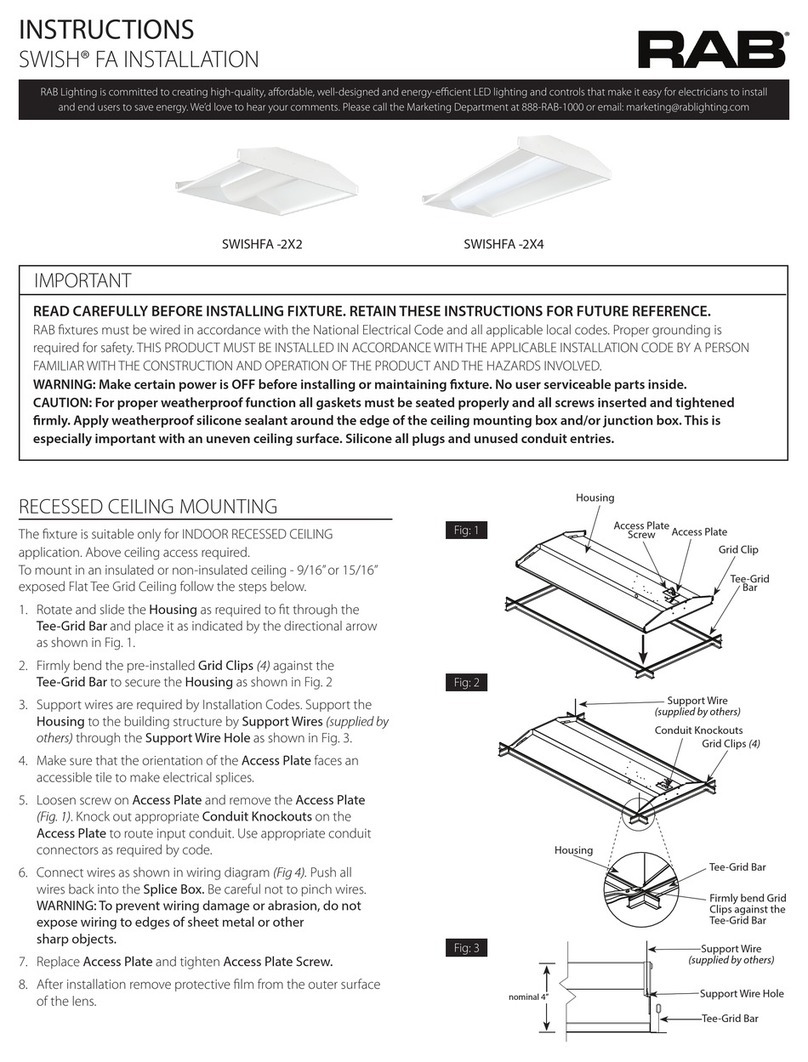
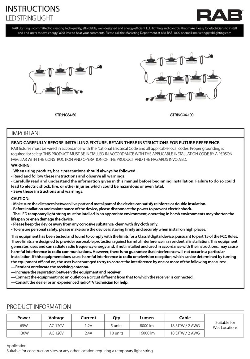
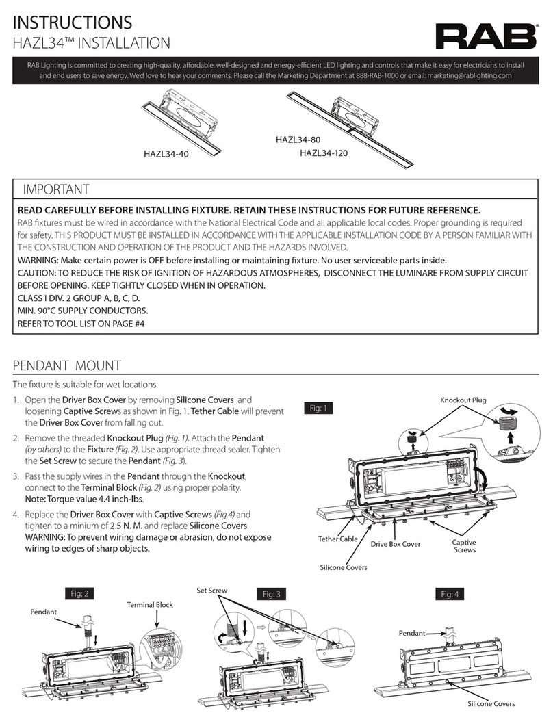
EXIT34-RG EMERGENCY EXIT SIGN
EXIT34-RG
EXIT34-RG/E
MI PORTANT
IMPORTANT SAFEGUARDS:
CAREFULLY BEFORE INSTALLING FIXTURE. R TAIN THESE INSTRUCTIONS FOR FUTURE REFERENCE.READ E
• When re-lamping, only use lamps specified in the exit sign. Using other lamp types may result in damage to the unit or unsafe
conditions.
• Battery in this unit may not be fully charged. After electricity is hooked up to unit, let the battery charge for at least 24 hours.
Normal operation of this unit should then take effect.
When using electrical equipment, basic safety precautions should always be followed including the following:
READ AND FOLLOW ALL SAFETY INSTRUCTIONS
• Do not use outdoors.
• Do not mount near gas or electric heaters.
• Equipment should be mounted in locations and at heights where it will not be subjected to tampering by unauthorized
personnel.
• The use of accessory equipment not recommended by the manufacturer may cause an unsafe condition.
• Do not use this equipment for other than its intended use.
• Before wiring to power supply, turn off electricity at fuse or circuit breaker.
• Consult local building code for approved wiring and installation.
• Installation and servicing should be performed by qualified personnel.
RAB fixtures must be wired in accordance with the National Electrical Code and all applicable local codes. Proper grounding is
required for safety. THIS PRODUCT MUST BE INSTALLED IN ACCORDANCE WITH THE APPLICABLE INSTALLATION CODE BY A PERSON
FAMILIAR WITH THE CONSTRUCTION AND OPERATION OF THE PRODUCT AND THE HAZARDS INVOLVED.
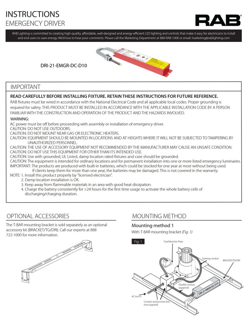
Ceiling and End Mount Installation
Interchangeable red or green lettering
1. Remove EXIT stencil from housing, set aside.
2. Place screws (provided) in holes on the canopy.
3. Remove the desired mounting hole plug located on theframe of
the sign. For ceiling mount, hole plug will be located on the top
of the housing. For wall mount, hole plug will be located on the
side of the housing.
4. Place canopy tab through the mounting hole of the housing until
the flat portion of the canopy is touching the housing frame. Lock
the canopy into place by sliding the canopy, without turning,
toward smaller end of the mounting hole until the tab is fully
engaged and locked into place. Once canopy is in the locked
position there will not be any side-to-side movement of the canopy.
5. Route EXIT input wires through canopy and through metal
mounting plate.
6. Make wiring connection. For 120V, use black and white wires. And
for 277V, use red and white wires. WARNING: Properly insulate the
unused lead with a wire nut (provided) or other approved means.
7. Push wire connections into the J-Box. Secure mounting plate to
junction box (hardware not included).
8. Secure the canopy to the steel mounting plate with screws installed in step 2.
9. Remove proper chevron(s) as required. When removing chevrons it may be helpful to remove the
color diffuser panel to allow easier access to the chevrons. If removing color diffuser panel it is important to
remember to reinstall the diffuser panel, securing with diffuser retention caps once chevron(s) have been removed.
10. Connect battery only after continuous AC power can be provided to the unit.
11. Secure face plate(s) to the housing.
12. Apply continuous AC power and press“TEST" button to check operation. See operation (battery back-up) for testing procedures.
HOLE PLUG-
REMOVE FOR
CEILING MOUNT
HOLE PLUG-
REMOVE FOR
WALL MOUNT
CANOPY
MOUNTING PLATE
CANOPY MOUNTING PLATE
EXIT34-RG EMERGENCY EXIT SIGN
WIRING DIAGRAMS
1. Remove the faceplate(s) from the unit’s housing.
2. Gently pop out the red diffuser lens from the faceplate(s). Replace
the green diffuser lens onto the faceplate(s).
3. Toggle the dip switch from R to G on the RED/GREEN switchable
LED board.
4. Replace the faceplate(s) no the housing to finish installation.
RED-to-Green Conversion
1. Remove the faceplate from the unit’s housing.
2. Remove the backplate by pushing out the two locking clips on the
inside of the unit's housing.
3. Attach the two EXIT faceplates to the housing to complete the
conversion.
Single-to-Double Face Conversion
Caution: Always turn off AC power to the equipment before servicing.
Servicing should be performed only by a qualified service technician.
Use only MANUFACTURER supplied replacement parts.
BATTERY: The battery supplied with the Battery Backup model
requires no maintenance. However, it should be tested periodically
and replaced when it no longer operates the connected fixtures for
the duration of a 30-second or 90-minute test. The battery supplied in
this equipment has a life expectancy of 5 years when used in a normal
ambient temperature of 72°F.
MAINTENANCE
National Electric Code (NEC) and NFPA life safety code regulations
require that routine tests need to be performed as listed below. Once
every month, the unit needs to be tested for duration of 30 seconds.
Push in hold the test switch to perform this test. Once every 12
months, a full 90 minute (per UL requirements) test needs to be
performed on the unit. Disconnect power to the unit and leave it in
the emergency mode. The LEDs should stay ON for at least 90 minutes.
TESTING
NOTE: Properly insulate the unused lead with a wire nut or other
approved means.
WARNING: Unused wires must be capped using enclosed wire nuts.
Fig: 3
Easy Answers
EX343-IN-0323
Cranbury, New Jersey 08512 USA
2023
Wall Mount Installation
1. Apply AC power to the unit. The LED Indicator should turn RED.
2. After the battery has been left to charge for 24 hours, test the unit
by pushing the switch. The LED indicator turns OFF and the LED
board stays ON.
3. When the switch is released, the LEDs turn OFF and the LED
indicator turns back to RED.
OPERATION (Battery Backup)
AC ONLY
BATTERY BACKUP
BATTERY
POWER SUPPLY
PC BOARD
RED/GREEN switchable LED board
RED 277VAC
BLACK 120VAC
WHITE COMM
DIP SWITCH
GREENRED
BATTERY
POWER SUPPLY
PC BOARD
RED/GREEN switchable LED board
RED 277VAC
BLACK 120VAC
WHITE COMM
DIP SWITCH
GREENRED
1. Remove EXIT stencil from housing, set aside.
2. Drill or knock out appropriate knockouts on backplate to fit junction
box mounting points.
3. Drill or knock out center hole in backplate for EXIT supply wire leads.
4. Route EXIT input wires through center hole of the backplate and
make wiring connection. For 120V, use black and white wires.
And for 277V, use red and white wires.
5. Secure backplate to junction box (hardware not included).
6. Connect battery only after continuous AC power can be provided
to the unit.
7. Remove proper chevron(s) as required. When removing chevrons it
may be helpful to remove the color diffuser panel to allow easier
access to the chevrons. If removing color diffuser panel it is
important to remember to reinstall the diffuser panel, securing with
diffuser retention caps once chevron(s) have been removed.
8. Apply continuous AC power and press “TEST" button to check
operation. See operation (battery back-up) for testing procedures.
This manual suits for next models

1

Other RAB Lighting Equipment manuals

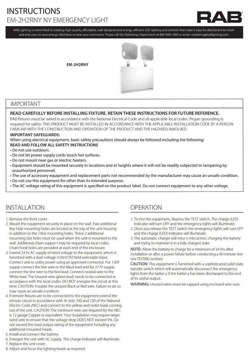
RAB EM-2H2RNY User manual

RAB

RAB EM-2H2RNY User manual

RAB HAZL34-40 User manual

RAB

RAB HAZL34-40 User manual

RAB STEALTH 360 User manual

RAB

RAB STEALTH 360 User manual

RAB SHARK - 8FT User manual

RAB

RAB SHARK - 8FT User manual

RAB X34 User manual

RAB

RAB X34 User manual

RAB EZPAN HE 1X4 User manual

RAB

RAB EZPAN HE 1X4 User manual

RAB PLC-9-V-8XX-BYP User manual

RAB

RAB PLC-9-V-8XX-BYP User manual

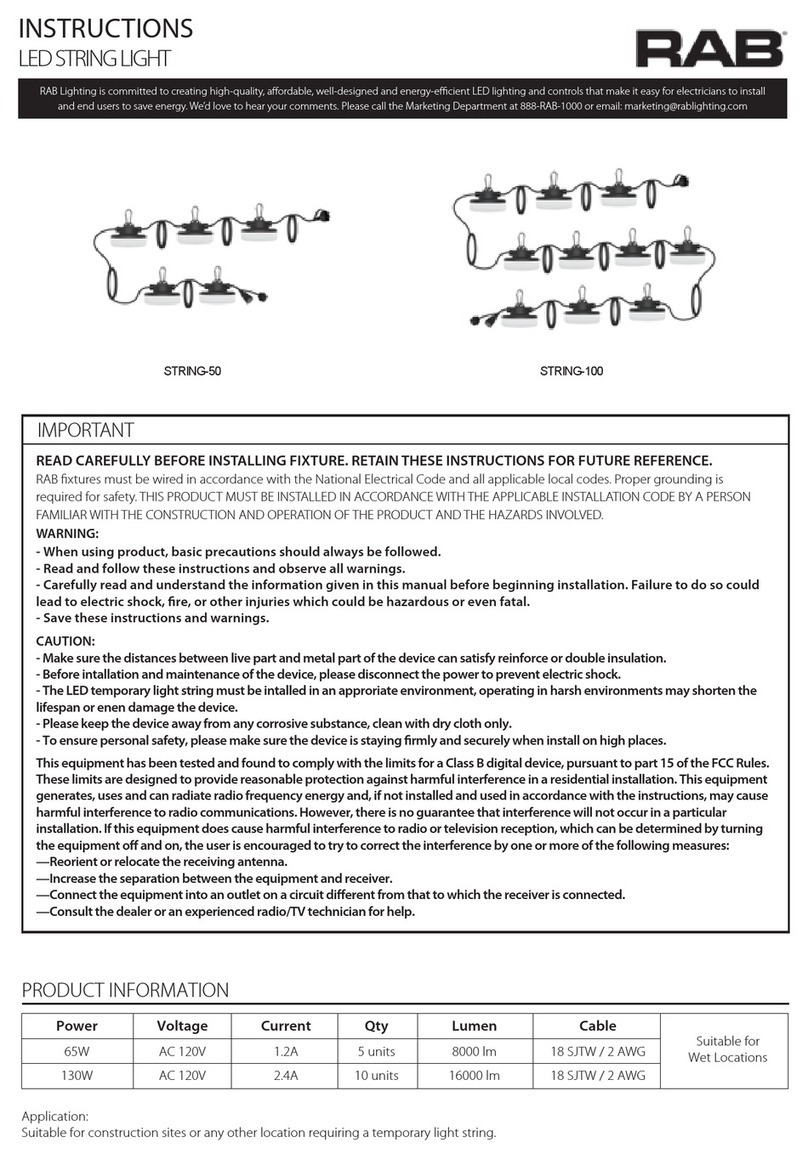
RAB STRING-50 User manual

RAB

RAB STRING-50 User manual

RAB STL200H/L User manual

RAB

RAB STL200H/L User manual

RAB T5HE-10-24P-8-EXT Series User manual

RAB

RAB T5HE-10-24P-8-EXT Series User manual

RAB EM User manual

RAB

RAB EM User manual

RAB GOTCHA PLUS GT500 User manual

RAB

RAB GOTCHA PLUS GT500 User manual

RAB T8 User manual

RAB

RAB T8 User manual

RAB GUS- 2FT User manual

RAB

RAB GUS- 2FT User manual

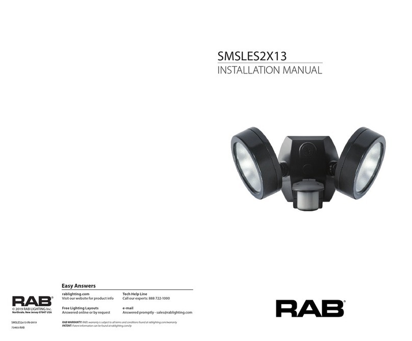
RAB SMSLES2X13 User manual

RAB

RAB SMSLES2X13 User manual

RAB SWISHFA -2X2 User manual

RAB

RAB SWISHFA -2X2 User manual

RAB ECOMBO34 User manual

RAB

RAB ECOMBO34 User manual

RAB TOMO- 2FT User manual

RAB

RAB TOMO- 2FT User manual

RAB FXLED User manual

RAB

RAB FXLED User manual

RAB DRI-21-EMGR-DC-D10 User manual

RAB

RAB DRI-21-EMGR-DC-D10 User manual

RAB STL360HB/L User manual

RAB

RAB STL360HB/L User manual

RAB LESLIE User manual

RAB

RAB LESLIE User manual

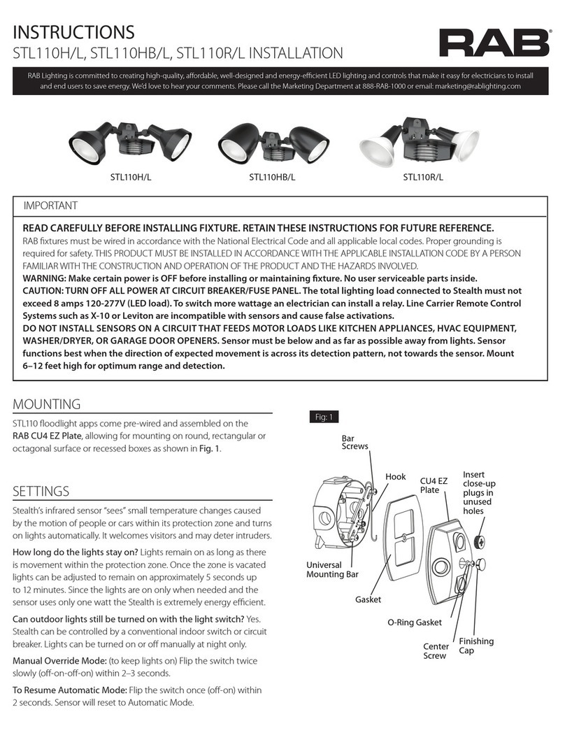
RAB STL110H/L User manual

RAB

RAB STL110H/L User manual

RAB X17 XFU 60W User manual

RAB

RAB X17 XFU 60W User manual

Popular Lighting Equipment manuals by other brands

Viessmann 6049 Operation manual

Viessmann

Viessmann 6049 Operation manual

Jameco Electronics 8x8x8 LED Cube manual

Jameco Electronics

Jameco Electronics 8x8x8 LED Cube manual

Axis T90B15 W-LED installation guide

Axis

Axis T90B15 W-LED installation guide

Confer Plastics STEP-1X ASSEMBLY, INSTALLATION AND USE MANUAL

Confer Plastics

Confer Plastics STEP-1X ASSEMBLY, INSTALLATION AND USE MANUAL

Jester Zero 88 operating manual

Jester

Jester Zero 88 operating manual

KAM Derby 8 instruction manual

KAM

KAM Derby 8 instruction manual

radiance 7201111 instruction manual

radiance

radiance 7201111 instruction manual

EAST OAK EO-PU22020 owner's manual

EAST OAK

EAST OAK EO-PU22020 owner's manual

BION TECHNOLOGIES firmus l RGBWquad user manual

BION TECHNOLOGIES

BION TECHNOLOGIES firmus l RGBWquad user manual

KAM KML412 manual

KAM

KAM KML412 manual

Victor Tools K031 Instructions for use

Victor Tools

Victor Tools K031 Instructions for use

Artecta Par 30 Tracklight - Warm on Dim V1 user manual

Artecta

Artecta Par 30 Tracklight - Warm on Dim V1 user manual

StreamLight PROTAC 90X USB user manual

StreamLight

StreamLight PROTAC 90X USB user manual

Stairville DMX Joker V2 512 Box quick start guide

Stairville

Stairville DMX Joker V2 512 Box quick start guide

Becen BC-410F user manual

Becen

Becen BC-410F user manual

Equinox Systems Domin8r IIEQLED53 user manual

Equinox Systems

Equinox Systems Domin8r IIEQLED53 user manual

Nicols TWIN LASER GB user guide

Nicols

Nicols TWIN LASER GB user guide

Nitecore NPL20 user manual

Nitecore

Nitecore NPL20 user manual

manuals.online logo
manuals.online logoBrands
  • About & Mission
  • Contact us
  • Privacy Policy
  • Terms and Conditions

Copyright 2025 Manuals.Online. All Rights Reserved.