HCIFitness PhysioStep LXT User manual
1
______________________________Owner’s Manual
HealthCare International, Inc.
PO Box 1509, Langley, WA 98260
p.360.321.7090 or 206.285.5219

2
SAFETY PRECAUTIONS
This exercise equipment was designed and built for optimum safety. However, certain precautions
apply whenever you operate a piece of exercise equipment. Be sure to read the entire manual
before assembly and operation of this machine.
Also, please note the following safety precautions:
1. Read all instructions carefully before using the machine.
2. Consult your physician or other health care professional before beginning this
or any type of exercise program.
3. Always wear proper exercise apparel when using the machine.
4. If at any time you feel faint, light-headed or dizzy while operating the machine, stop exercise
immediately. You should also stop exercising if you are experiencing pain or pressure.
5. Keep children and pets away from the machine while in use.
6. Only one person can use the machine at a time.
7. Make sure your machine is correctly assembled before you use it. Be sure all screws, nuts, and
bolts are tightened prior to use and retighten periodically.
8. Do not operate this or any exercise equipment if it is damaged.
9. Keep hands and feet away from any moving parts. Do not insert any objects into any openings.
10.Keep clothes, jewelry or loose items away from moving parts.
NOTE:
Maximum weight capacity for the PhysioStep LXT is 400 lbs (182 kgs)
WARNING
BEFORE BEGINNING ANY EXERCISE PROGRAM CONSULT YOUR PHYSICIAN. THIS IS
ESPECIALLY IMPORTANT FOR INDIVIDUALS OVER THE AGE OF 35 OR PEOPLE WITH
PRE-EXISTING HEALTH PROBLEMS. READ ALL INSTRUCTIONS BEFORE USING THIS
FITNESS EQUIPMENT. WE ASSUME NO RESPONSIBILITY FOR PERSONAL INJURY OR
PROPERTY DAMAGE SUSTAINED BY OR THROUGH THE USE OF THIS PRODUCT.
3
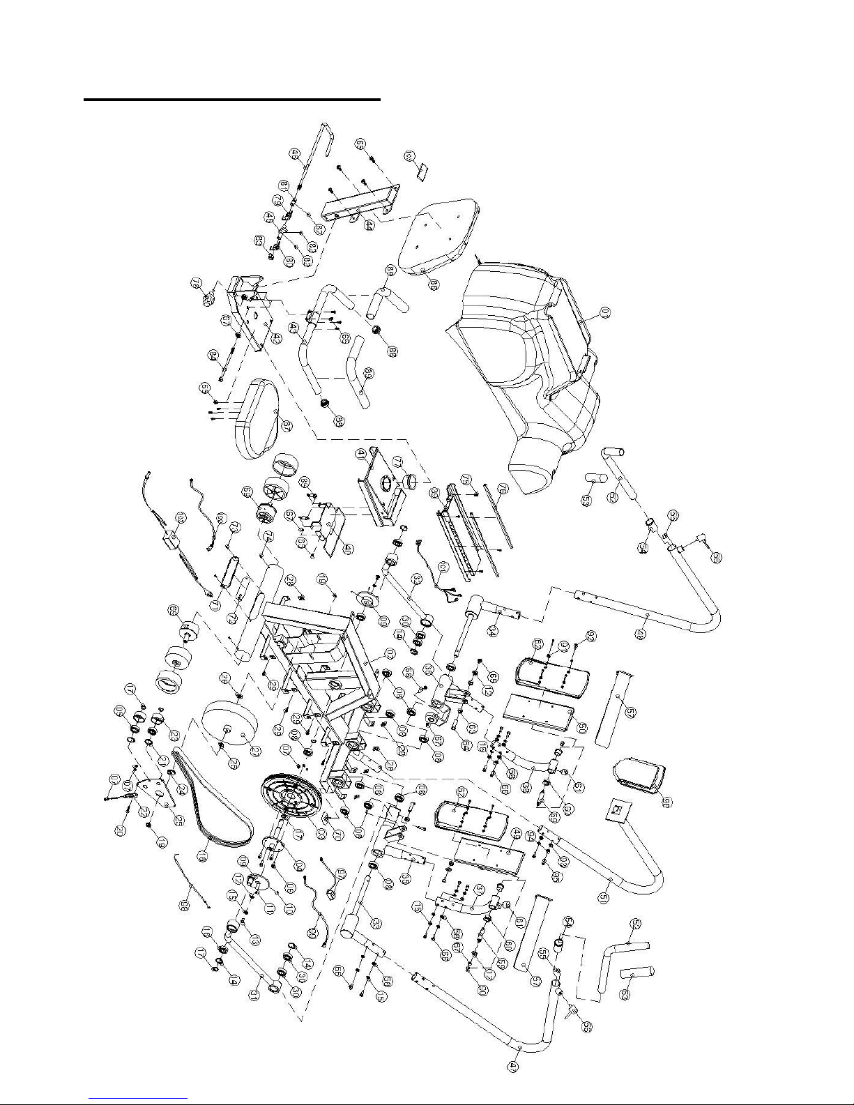
EXPLODED DRAWINGS

4
PARTS LIST
No.
Description
Qt'y
No.
Description
Qt'y
1
Chain Cover
1
27
Magnetic Flywheel
1
2
Main Frame
1
28
Screw Hole Clip
12
3
Belt Pulley
1
29
"+" Bolt ST4*12L
12
4
Pulley Axle
1
30
Ball Bearing 6004ZZ
4
5
Ball Bearing 6204ZZ
2
31
Connecting Parts (R)
1
6
Hexagonal Bolt M6*15L
4
32
Connecting Parts (L)
1
7
Lock Nut M6
8
33
Moving Handle Axis( R )
1
8
Ball Bearing 6004ZZ
8
34
Moving Handle Axis ( L )
1
9
Eccentric Wheel
2
35
Moving Pedal Set ( R )
1
10
Stoppage Screw M5*6
4
36
Moving Pedal Set ( L )
1
11
Key 5*5*15L
2
37
Pedal Foot ( R )
1
12
Washer Ø8.5*Ø26*1T
10
38
Pedal Foot ( L )
1
13
Hexagonal Bolt M8*15L
4
39
Change pipe
1
14
C-ring R-42
4
40
Dipping Handle
1
15
Spring Washer SW8
38
41
Seat Moving Set
1
16
Spherical bearing
2
42
Rear Stabilizer
1
17
C-ring S-20
6
43
Seat Handle
1
18
Belt
1
44
Back cushion support
1
19
Nut Flange
2
45
Files block
1
20
Hexagonal Bolt M6*35L
1
46
Dipping Handle
1
21
C-ring R-47
2
47
Moving Handle (R)
1
22
Metal Parts
1
48
Moving Handle (L)
1
23
Idler Wheel Ø53*Ø43*21
2
49
Pedal (R)
1
24
Retaining Washer
1
50
Pedal (L)
1
25
Idler Support
1
51
Computer Post
1
26
Lock Nut 3/8*3t
2
52
Moving Handle Set
2
5
PARTS LIST
No.
Description
Qt'y
No.
Description
Qt'y
53
Handle Sponge
2
79
Clockwise Spring
1
54
Place control
2
80
Chemistry Spring
1
55
Hand fixed block
2
81
Compass tube
1
56
Knob
2
82
Stoppage Screw M6*6
3
57
Pedal Strap
2
83
Nylon Nut M10
1
58
Curved Washer Ø8.5*Ø22*1.5T
28
84
Hexagonal Bolt M8*100L
1
59
Shaft For Pedal Bracket
2
85
Spring
2
60
Bushing Ø19.1*Ø32*Ø25.5*15L
2
86
Back Cushion
1
61
Rubber Cushion
2
87
Seat
1
62
Pedal
2
88
End Cap For Hand Pulse Sensor
2
63
Bushing-Ø25*Ø18*8.5L
4
89
Handle Sponge
2
64
Axle
2
90
Nut Cover M8
4
65
Hexagonal Bolt M8*15L
16
91
Washer Ø6.2*Ø13*1.2T
8
66
Hexagonal Bolt M8*15L
28
92
Hexagonal Bolt M6*25L
8
67
Nylon Nut M8
9
93
Curved Washer Ø6.2*Ø13*1T
8
68
Hexagonal Bolt M8*65L
2
94
Spring Washer SW6
8
69
Rear Leg Wheel
2
95
Hexagonal Bolt M6*10L
8
70
Adjustment Fix Cushion (28*11)
2
96
Computer
1
71
Socket Cover
1
97
DC Motor
1
72
Input Socket
1
98
Tension Cable
1
73
Screw M5*15L
2
99
Sensor Wire
1
74
"+" Bolt ST5*12L
2
100
Power inlet
1
75
Hexagonal Bolt M8*12L
6
101
Control Wire
1
76
Moving Plastic post
2
102
Adapter
1
77
Bushing
1
103
Square Cap-40*80
1
78
Knob
1

6
Dear Valued Customer,
Thank you for your recent purchase of the PhysioStep LXT –Recumbent
Linear Stepper from HCI Fitness. We believe that you have purchased one of
the highest quality and affordable recumbent steppers on the market today.
Prior to using your new PhysioStep LXT please review the operators manual
and product tips to maximize your workout experience.
Wishing you the best of luck in reaching your health and fitness goals!
HealthCare International is a leading supplier and distributor of innovative products for Health,
Wellness, Fitness & Active Aging. Visit our website –www.HCIFitness.com for information
on all of our products.
Warranty Information:
(Your Serial Number is found on a white sticker at the rear base of the unit and on the box)
Serial #:_________________ Purchase Date:_______________
3 Year Parts Warranty, One Year Labor, Lifetime Frame
NOTE
Before you start to assemble this unit, please note that some of the parts and screws
needed for assembly are already in place on the unit.
TOOL SET:
(112) 5mm Allen Wrench Tool
1pc
(113) Extended 6mm Allen Wrench Tool
1pc
(111) 13*15 Screwdriver/Wrench Combo Tool
1pc
7
ASSEMBLY INSTRUCTIONS:
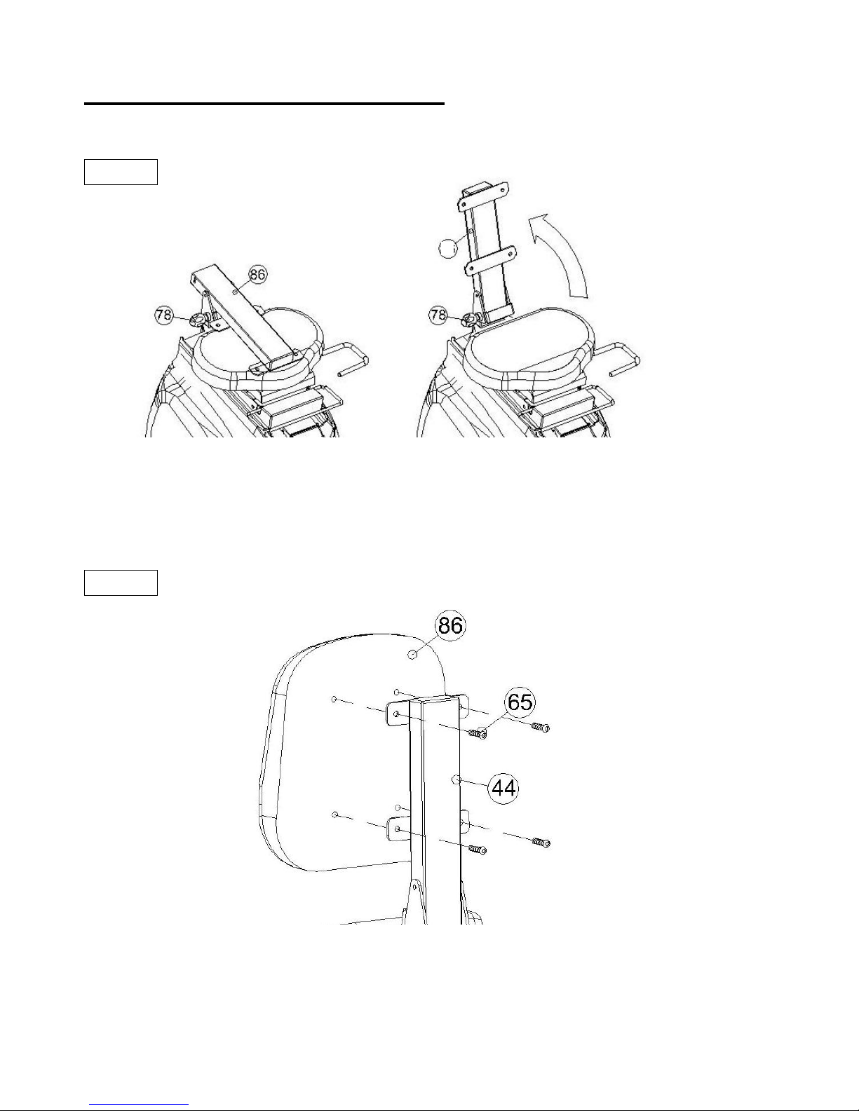
STEP 1
Hold Knob (78) and pull to release the Back Cushion Support (44) place it in an upright position.
Make sure the Knob (78) is then fixed firmly back in place to secure the Back Cushion Support (44)
STEP 2
Assembly of Back Cushion (86) secure the Back Cushion Support (44) by using Hexagonal Bolt
M8*15L (65) make sure the bolts are securely tightened.
44

8
ASSEMBLY INSTRUCTIONS:
STEP 3
1. Install Moving Handle R (47) to Moving Handle Axis R(33) by using the Hexagonal Bolt M8*15L
(66) and Spring Washer SW8 (15) and Curved Washer Ø8.5*Ø22*1.5T (58) and make sure the
bolts are securely tightened.
2. Install Moving Handle L (48) to Moving Handle Axis R(33) by using the Hexagonal Bolt M8*15L
(66) and Spring Washer SW8 (15) and Curved Washer Ø8.5*Ø22*1.5T (58) make sure the bolts
are securely tightened.
STEP 4
Release Knobs (56) and then insert Moving Handle Set (52) into Moving Handle R (47) and Moving
Handle L (48) tighten the screw Knob (56) according to user’s preference. The Handles can be
adjusted to various users’ lengths.
9
ASSEMBLY INSTRUCTIONS:
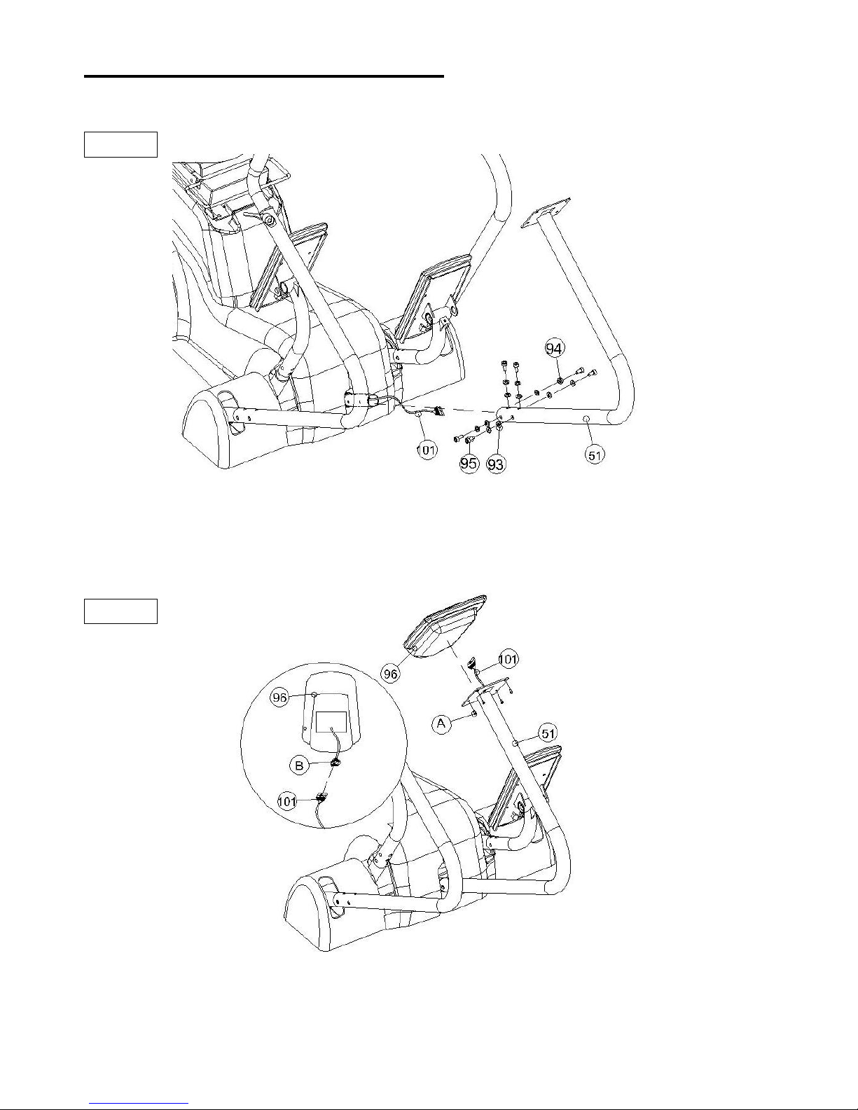
STEP 5
Taking Control Wire (101) feed it through the Computer Post (51) attach the Computer Post (51) to
Main Frame (2), using the Curved Washer Ø6.2*Ø13*1T(93), Spring Washer SW6(94) and Hexagonal
Bolt M6*10L (95 make sure the bolts are securely tightened.
STEP 6
Remove Bolts M5*10L(A) from the back of the Computer (96). Connect Control Wire Computer
(B) to connect with Control Wire (101). Then using Bolt M5*10L(A) attach the Computer (96) to
Computer Post (51) make sure the bolts are securely tightened.
.

10
QUCIK TIPS:
AC Adaptor: The PhysioStep LXT does need to be plugged into a standard electrical outlet.
The AC adaptor connects at the rear base of the unit, at ground level, on the end of the unit that
is beneath the seat. The display is powered by the adaptor and does not need batteries.
Quick Start: If you would like to start a simple workout, just press the Start Button and then
use the arrows to set the resistance. It will automatically start you at level 1.
Full Extension: When one side of the PhysioStep LXT is fully extended, to “un-lock” the
extension simply pull the opposite handle towards you while keeping your feet on the pedals.
For example, if the right pedal is furthest from the seat, pull on the left handle to release the
extension.
Heart Rate: If you would like to monitor your heart rate while using the PhysioStep LXT,
simply use any chest belt. There is a wireless heart rate receiver in the display and it will
automatically connect with all common brands of chest belts (i.e. Polar, Garmin etc). If you
don’t already have one, local sporting goods stores are a good place to purchase. The FT1 is
one model that works well.
Levelers: There are levelers in the front of the unit, beneath the shroud. Please adjust the
levelers to stabilize the unit on your floor.
MANUAL: PHYSIOSTEP LXT DISPLAY CONSOLE
This manual covers the following categories:
-Key Functions
-Operating Ranges
-Operating Instructions
-Additional Information
11
Key Functions
There are a total of 6 keys on the monitor; UP, DOWN, ENTER, START/STOP, RECOVERY
AND MODE.
A. UP (▲): Selects or increases the values of PROGRAMS, TIME, WATT, CALORIES,
TARGET HEART RATE, AGE, DISTANCE.
B. DOWN (▼): Selects or decreases the values of PROGRAMS, TIME, WATT, CALORIES,
TARGET HEART RATE, AGE, DISTANCE.
C.ENTER: Selects the functions from PROGRAMS, TIME, WATT, CALORIES, TARGET
HEART RATE, AGE, DISTANCE and 10 columns. The selected function will flash.
Please note that not all of the functions can be selected in every program.
D.START/STOP: Starts or stops the program that was selected. Pressing this button for 2
seconds will reset the monitor.
E. MODE: Changes the display of the values between CALORIES or WATTS. The values of
RPM and WATTS show at the same time.
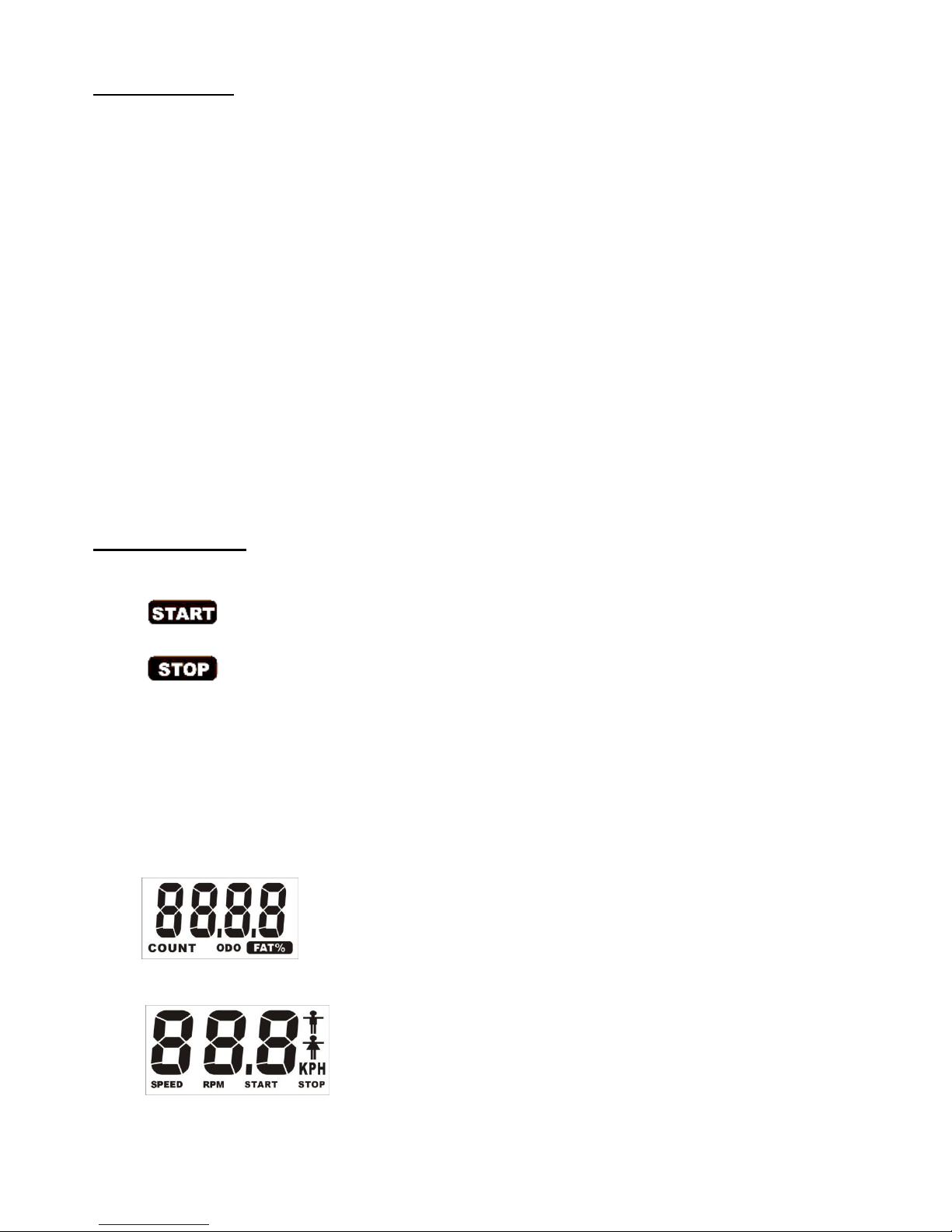
Display/Monitor
A. START: Indicates the program selected has started.
B. STOP: Indicates the program selected has stopped.
C.PROGRAM: Indicates the programs selected from PROGRAM 1 to PROGRAM 16.
D.LEVEL: Indicates the level of resistance selected from LEVEL 1 to LEVEL 16.
E. TIME Display: Indicates only 1 value of TIME displayed depending on the program.
F. DISTANCE/FAT%: Indicates only one value of DISTANCE, ODOMETER or FAT% displayed
depending on the program.
G.RPM/SPEED: Indicates the value of RPM or Speed.

12
H.CAL/WATT/BMR Display: Indicates only one value of CAL, OR WATT displayed depending
on the program.
I. TARGET H.R./AGE Display: Indicates only one value of TARGET HEART RATE, or AGE
displayed depending on the program.
J. HEART RATE Display: Indicates only one value of HEART RATE displayed.
K. Resistance Profiles: There are 10 columns of resistance bars, and 8 bars in each column.
Each column represents 3 minutes of your workout (without the change of TIME value), and
each bar represents 2 levels of resistance.
Operating Ranges
Values
Range (DISTANCE
up)
DISTANCE
down
Preset
Increment
(Decrement)
PROGRAM
1 ~ 16
16 ~ 1
1
1
LEVEL
1 ~ 16
16 ~ 1
N/A
1
TIME
0:00 ~ 99:59
99:00 ~ 5:00
0:00
1:00
DISTANCE
0 ~ 9999
9990 ~ 10
0
1
WATT
30 ~ 300
300 ~ 30
100
10
CALORIES
0 ~ 9999
9990 ~ 10.0
0
0.1
AGE
10 ~ 99
99 ~ 10
30
1

13
Operating Instructions
A. Exercising With a Specific Goal:
1.TIME Control: Set your workout duration for a specific amount of time.
2.DISTANCE Control: Set your workout duration for a specific DISTANCE.
3.WATT Control: Set the WATTS for a workout and the display computer will make
adjustments to maintain the selected WATTS level.
4.CALORIE Control: Set your workout duration to burn a specific number of calories (Except
in Program 8 & 17)
5.HEART RATE: If you would like to monitor your heart rate while using the PhysioStep LXT,
simply use any chest belt- there is not contact heart rate, so you must be using a heart
rate monitor to show your pulse on the display.
B. Manual Program:
PROGRAM 1 is a manual program. Press “ENTER” key to select TIME, DISTANCE,
CALORIES and AGE. Then, press ▲ or ▼ key to adjust the values. Press
“START/STOP” key to begin exercising. Users may adjust the level (by pressing ▲ or ▼
during the workout) with a period of time or a certain DISTANCE. With the input of age,
the computer may suggest a target heart rate to exercise. The suggested heart rate is
85% (220 –age). So, if the heart rate detected equals to or greater than the TARGET H.R.,
the value of HEART RATE will keep flashing. Please note that the flashing heart icon is a
warning for users to slow down or decrease the resistance.
C. Preset Programs:
PROGRAMS 2 through PROGRAM 7 are the preset programs. Press “ENTER” key to
select TIME, DISTACE, CALORIES and AGE. Then, press ▲ or ▼ key to adjust the
values. Users may exercise at the selected level of resistance for selected intervals as the
profiles show. Press “START/STOP” key to begin exercising. Users may adjust the
resistance level by pressing ▲ or ▼ during the workout. When you input your age, the
computer may suggest a target heart rate. The suggested heart rate is 85% (220 –age).
So, if the heart rate detected equals to or greater than the TARGET H.R., the value of
HEART RATE will keep flashing. Please note that the flashing heart icon is a warning
for users to slow down or decrease the resistance.

14
D. Heart Rate Control Programs:
Programs 8 through 11 are the Heart Rate Control Programs. In program 8, press “Enter”
key to select TIME, DISTANCE, CALORIES and TARGET H.R. Users may setup a target
heart rate to exercise in a period of time or a certain distance. In Program 9 to Program 11,
press “Enter” key to select TIME, DISTANCE, and AGE. Then, press ▲ or ▼ key to adjust
the values. Users may exercise in a period of time or a certain count with 60% Max Heart
Rate in Program 9, 75% Max Heart Rate in Program 10 , and 85% Max Heart Rate in
Program 11. After pressing “START/STOP” key to exercise, please also apply the heart
rate detector appropriately. In these programs, the computer will adjust the level of loading
according to the heart rate detected. For example, the level of loading may increase while
the heart rate detected is lower than TARGET H.R. Also, the level of loading may
decrease while the heart rate detected is higher than TARGET H.R. As a result, the user’s
heart rate will be adjusted to close the TARGET H.R. in the range of TARGET H.R. –5 and
TARGET H.R. +5.
E. Creating User Profile Programs:
Programs 12 through 15 are the user profile programs. When setting up your program,
select the TIME, DISTANCE, CALORIES, AGE and resistance level. The values selected
for your profile will be stored the memory after setup. Press “START/STOP” key to begin
exercising. You can change the resistance level during your workout at anytime by
pressing ▲ or ▼ key. Please note, this will not store the change in the profile memory.
The computer may suggest a target heart rate to exercise. The suggested heart rate is
85% (220 –age). So, if the heart rate detected equals to or greater than the TARGET H.R.,
the value of HEART RATE will keep flashing. Please note that the flashing heart icon is
a warning for users to slow down or decrease the resistance.
F. Watt Independent Program:
Program 16 is a Watt Independent Program. Press the “ENTER” set the TIME,
DISTANCE, WATT, and AGE. Press “START/STOP” key to begin exercising.During
exercise, the level of resistance is not adjustable. In this program, the display computer
will adjust the level of resistance according to the preset WATT value. The level of
resistance may increase if speed is too slow in order to maintain the watts. Also, the level
of resistance will automatically decrease if the speed is too fast. As a result, the calculated
WATTs will remain close to the WATTS preset.
G. Pulse Recovery:
To check your heart rate during recovery this program scales your progress from 1.0 to 6.0.
1.0 is “the best” and 6.0 is “the worst”, increments are 0.1. In order to rate your recovery
correctly, perform this test right after your workout is finished, by pressing the “PULSE”key.
In order to register your heart rate on the display you must be wearing a heart rate monitor.
The test will last for 1 minute and the result will show in the display.
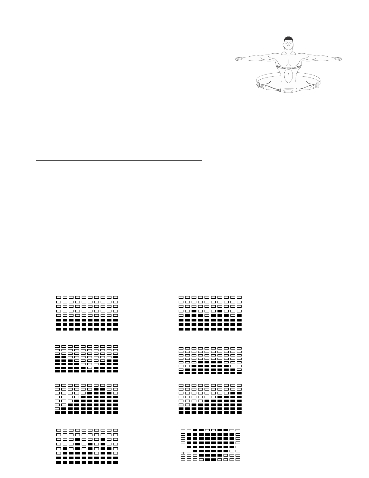
15
For Optional Heart Rate Chest Strap:
This is equipped with Telemetry, the heart
rate monitoring system in which electrodes, pressed against the skin,
transfer heart rate signals to the console. These
electrodes are attached to a chest strap that the user wears during
the workout. The chest strap is optional. See the drawing of Right side
to show you how to correctly wear the strap on your chest.
The electrodes which have two grooved surfaces inside of the
strap must remain wet to transmit accurately the electrical impulses
of the heart back to the receiver. Moisten the electrodes is very important and be sure to fasten the
strap correctly below your pectoral muscle.
Things You Should Know Before Exercising
A. The values calculated or measured by the computer are for exercise purpose only, not for
medical purpose.
B.Programs Selection:
There are 16 workout programs and 1 Recovery program. Programs include:
1 –7 Preset Programs, 8-11 Heart Rate Control Programs, 12-15 User Profile Programs,
16 WATT Control Program, and 1 Pulse Recovery Program.
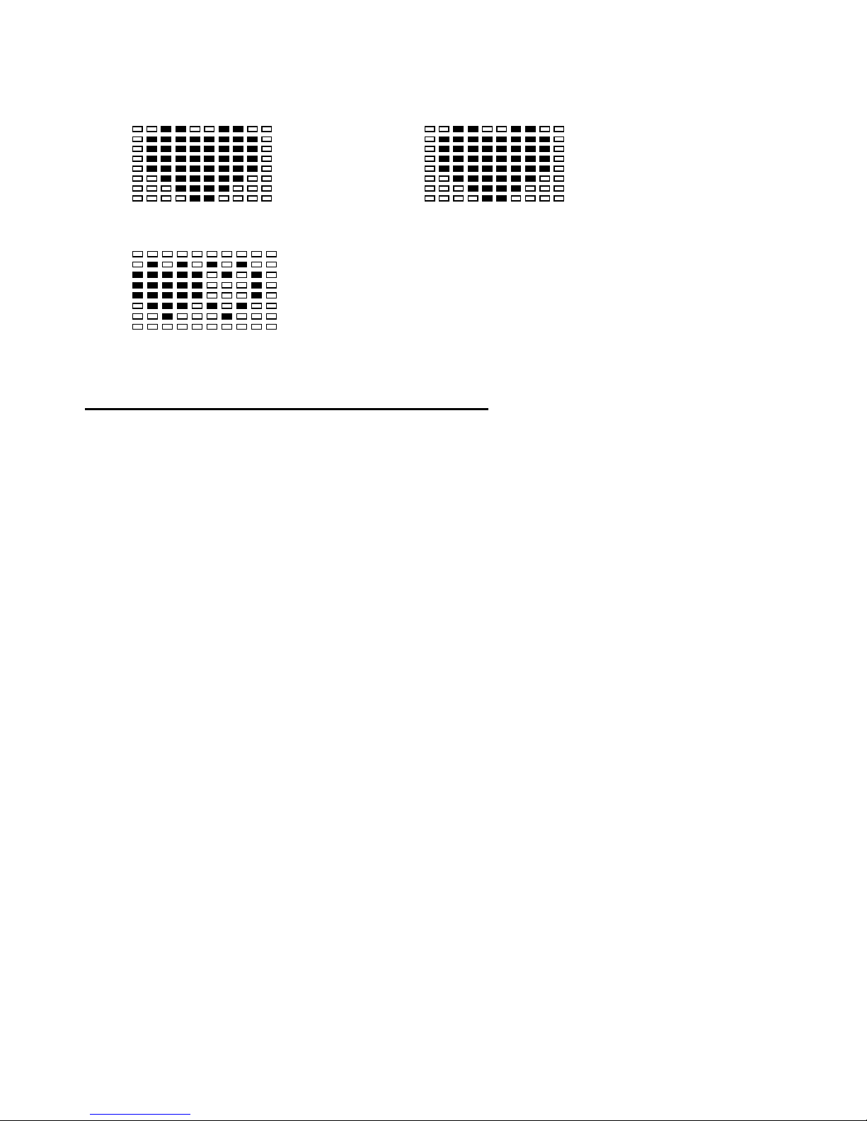
C.Program Graph:
Each graph shows the level of resistance during each program interval.
Program 1 (Manual) Program 2 (Rolling)
Program 3 (Valley) Program 4 (Fat Burn)
Program 5 (Ramp) Program 6 (Mountain)
Program 7 (Intervals) Program 8 (Target HR)
16
Program 9 (60% H.R.C.) Program 10 (75% H.R.C.)
Program 11 (85% H.R.C.)
MAINTENANCE AND TECHNICAL DATA
1.1 Maintenance Tips
Keep the PhysioStep LXT well maintained to ensure peak performance and safety.
Clean the display console and all exterior surface parts routinely. Use a soft cotton cloth and a
soft cleaner for best results. Do not use Ammonia or acid based cleaners.
Vacuum the area directly surrounding and under the unit regularly.
1.2 Routine Maintenance Schedule
Clean the following items weekly:
Console and Overlay and all other exterior parts, Handle Bar, Seat.
Routinely inspect the following items monthly and adjust or tighten if necessary:
Leg Levelers, Seat Adjust Position Knob, Seat Upright Adjust Knob, all Nuts and Bolts and the
Console Control Wire.
Hardware for console.
Hardware for Handlebar and Frame.

17
1.3 Trouble Shooting Guide for the PhysioStep LXT
Symptom
Possible Cause
Solution
The LCD Screen does not
display anything when in use
The Adaptor is not plugged in?
Check that the Adaptor is correctly
connected to the Main Power
Socket and is correctly connected
to the Computer.
The Computer is faulty.
Replace the Computer by
contacting your dealer.
The Speed Display shows only
zero’s when in use
The Computer isn’t receiving a
signal from the Speed Sensor?
(1)Check that the Sensor Magnet
is correctly fitted and passes in
front of the Sensor.
(2)Check the gap between Speed
Sensor and the Magnet is correct
5mm or less.
(3)Check that all the Computer
Plugs and Sockets are FIRMLY
and correctly connected.
(4)Check that the Computer Wires
are not damaged.
The Sensor is faulty.
If all these Checks fail, then
replace the Sensor.
The Computer is faulty.
Replace the Computer by
contacting your dealer.
The LCD Screen Partially
Displays
The connection between the
Circuit Board and the LCD Screen
Membrane is loose, gently press
down on the LCD Screen, If the
LCD Screen Partial Display
disappears then it is a connection
problem.
The connection between the
Circuit Board and the LCD Screen
Membrane is Misaligned. If this is
the problem you might be able to
see that the LCD Screen is on a
slight angle and NOT inline or
parallel with the Computer Case.
No Pulse Signal or incorrect
Chest Belt Signal
The Computer is NOT receiving a
pulse Signal.
Check that you are wearing the
chest belt correctly.
The Computer is receiving a faint
of Intermittent Pulse Signal.
(1) two grooved surfaces inside of
the strap must remain wet to
transmit accurately the electrical
impulses
of the heart back to the receiver.
(2) Moisten the electrodes is very
important and be sure to fasten
the strap correctly below your
pectoral muscle.
(3)Clean the Pulse Sensors to
ensure a good contact between
your body and the Pulse Sensors.

18
E1
No signal from motor gear
(1)Review the Assembly
Instructions and check that all the
Computer Plugs and Sockets are
FIRMLY and correctly connected.
(2)Review the unit’s Magnetic
Resistance System to ensure that
it is set correctly and they be at it
can freely be adjusted. A
symptom of the previous problem
is the Motor will struggle to adjust
the resistance and will start
making an abnormal sound. If this
happens the Motor may already
be damaged by some kind of
interference. After freeing the
interference the Motor will have to
be checked that it still correctly.
(3)Motor Problems
a. Symptoms include an unusually
loud noise coming from the Motor,
which means the Gears are NOT
meshing correctly. Try reversing
the resistance and try again. If this
fails then replace the Motor.
b. If the Motor fails to move at all
then please recheck as per
Solutions.
(4)Above. If this fails then Replace
the Motor.
E2
The Computer cannot interface
with the IC Chip
Disconnect the Adaptor and /or
remove the Batteries. Reconnect
the Adaptor and/or the batteries.
This will REBOOT the IC Chip and
may help the Computer interface
with the IC Chip.
Remove and reinsert the IC Chip.
If reinsertion fails then Replace
the IC Chip with a New IC Chip.
E5
Auto-tension (DISTANCE) is not
disconnected from zero point.
(1)Review the unit’s Magnetic
Resistance System to ensure that
it is set correctly and they be at it
can freely be adjusted. A symptom
of the previous problem is the
Motor will struggle to adjust the
resistance and will start making an
abnormal sound. If this happens
the Motor may already be
damaged by some kind of
interference. After freeing the
interference the Motor will have to
be checked that it still correctly.
(2)Motor Problems
a. Symptoms include an unusually
loud noise coming from the Motor,
which means the Gears are NOT
meshing correctly. Try lowering
the resistance and try again. If this
fails then replace the Motor.
b. If the Motor fails to move at all
then please recheck as per
Solutions. (3)Above. If this fails
then Replace the Motor.
Table of contents
Other HCIFitness Fitness Equipment manuals


