HCL Smart Band SM-FT-1000 Instruction Manual

SM-FT-1000 Banding Tool
Operation, Parts & Safety Manual
Original Instructions

Tooling
Index
Health & Safety
1.1 Warning & Safety Instructions
Torque Wrenches
2.1 Options
Operation
3.1 Using the Tool
3.2 Smart®Band Hybrid & Compact
Servicing
4.1 Servicing
4.2 Troubleshooting
4.3 Parts List
Depending on set up, this tool is designed to assemble the following HCL Smart®products:
– Smart® Tie 20mm (¾˝)
– Smart® Tie 32mm (1¼˝)
– Smart® Band 19mm (¾˝) Hybrid & Compact
– Smart® Band 32mm (1¼˝) Hybrid & Compact
Follow the instructions described to achieve safe operation.
Note: This tool is not suitable for Smart®Band Standard Systems
www.hclfasteners.com

www.hclfasteners.com
Read these instructions carefully:
Whilst Smart®Band and Smart®Tie are considered to be
signicantly safer than alternative metallic solutions, failure
to follow these instructions can still result in personal injury.
General safety considerations:
1. STRAP BREAKAGE HAZARD
Smart®Band and Smart®Tie are free from sharp metallic edges however it is important to understand that improper
operation of the tool or sharp corners on the load can result in strap breakage during tensioning that could result in the
following:
– A sudden loss of balance causing you to fall
– Both tool and strap ying violently towards your face
Failure to place the strap properly around the load, an unstable or shifted load, could result in a sudden loss of strap tension
during tensioning. This could result in a sudden loss of balance causing you to fall.
Positioning yourself in-line with the strap during tensioning, can result in personal injury from ying strap or tool. When
tensioning, position yourself to one side of the strap and keep all bystanders away.
2. TRAINING
This tool must not be used by persons not properly trained in its use. Be certain that you receive proper training from your
employer. If you have any questions contact your HCL representative.
3. EYE INJURY HAZARD
Failure to wear safety glasses with side shields can result in eye injury or blindness. Always wear safety glasses
with side shields which conform to ANSI Standard Z87.1 or EN 166.
4. CUT HAZARD
Although the Smart®Band and Smart® Tie are not metallic and therefore signicantly less likely to cause cuts to
hands or ngers, it is still strongly recommended that the operator wear protective gloves.
5. FALL HAZARD
Maintaining improper footing and/or balance when operating the tool can cause you to fall. Do not use the tool when you
are in an awkward position.
6. TOOL CARE (for further information see Servicing section)
– Inspect and clean the tool daily. Replace all worn or broken parts.
– Lubricate all moving parts approximately every 50 hours of use.
– If used in sea water, wash off immediately with fresh water after use. Dry and lubricate.
Health & Safety - Warning & Safety Instructions
1.1

www.hclfasteners.com
Torque Wrenches - Options
Mountz – FGC-10A (Factory set to speciced torque – Suitable for Marine use).
For use with: Material
Smart®Tie 20mm (¾˝)
PA66 (Nylon 6.6)
PA12 (Nylon 12)
PK
PPS
Smart®Tie 32mm (1¼˝)
PA12 (Nylon 12)
PPS
Smart®Band Hybrid 19mm (¾˝)
Smart®Band Compact 19mm (¾˝)
PA66 (Nylon 6.6)
PA12 (Nylon 12)
PPS
POM (Acetal)
Mountz – FGC-30A (Factory set to speciced torque – Suitable for Marine use).
For use with: Material
Smart®Tie 32mm (1¼˝)PK
Smart®Band Hybrid 32mm (1¼˝)
Smart®Band Compact 32mm (1¼˝)
PA66 (Nylon 6.6)
PA12 (Nylon 12)
PPS
Norbar – TTi20 (Variable torque setting – Not advised for Marine use).
For use with: Material
All product types
PA66 (Nylon 6.6)
PA12 (Nylon 12)
PK
PPS
POM (Acetal)
2.1

www.hclfasteners.com
5
Attach Torque wrench to the square drive at
the rear of the tool.
Optional – Lock Torque wrench to square drive
using a 4mm hexagon key
3
Wrap band around the application...
...and insert band into other end of buckle
4
Pull band tight by hand, making sure teeth are
fully engaged with band
Operation - Using the Tool with Mountz Torque Wrench
1
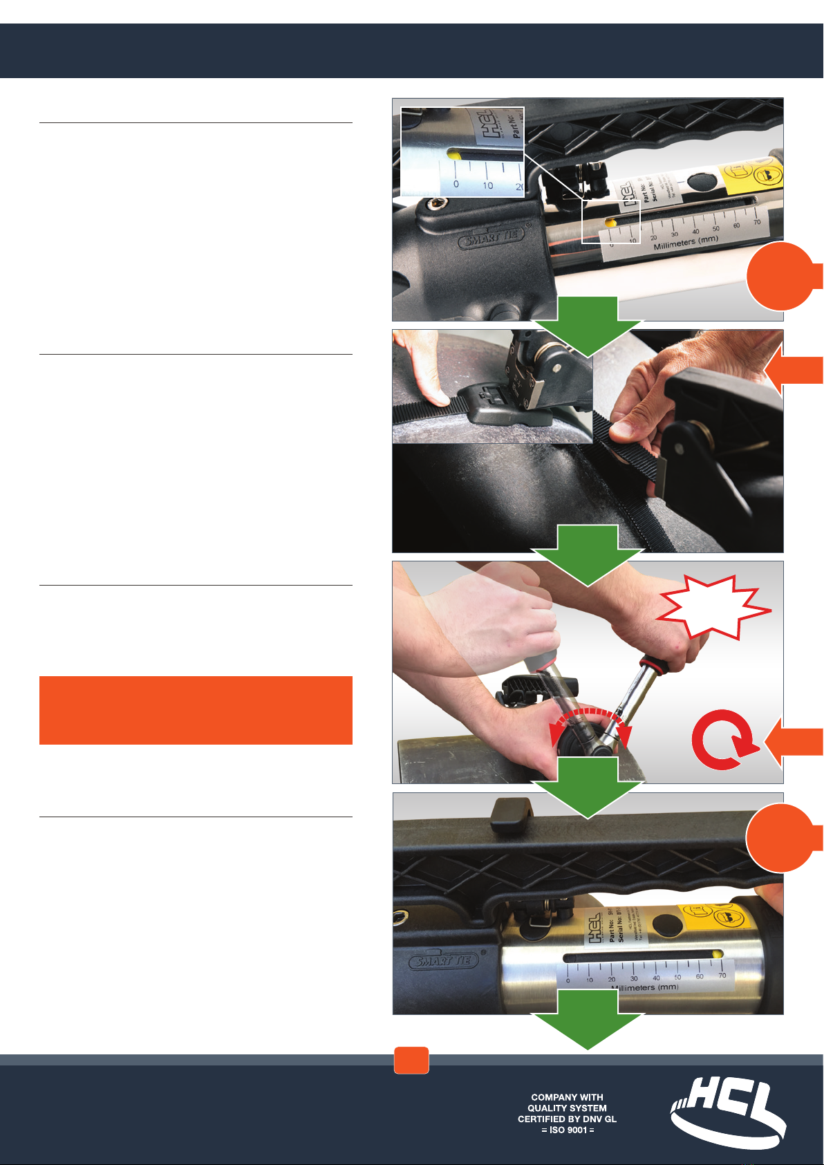
Insert band fully into xed end of the buckle
2
Pull back band to engage latch teeth and push
down rmly on the latch using the thumb or
nger to ensure full engagement
WARNING – Ensure latch is fully engaged
with band before tightening. Latch not fully
engaged could lead to premature failure of
system when tightening
TEETH ENGAGED
NOTE – Steps 1 & 2 are not applicable to
Smart®Tie
3.1

www.hclfasteners.com
9
Is the yellow marker in the ‘70mm’ position
(tool has run out of movement)?
8
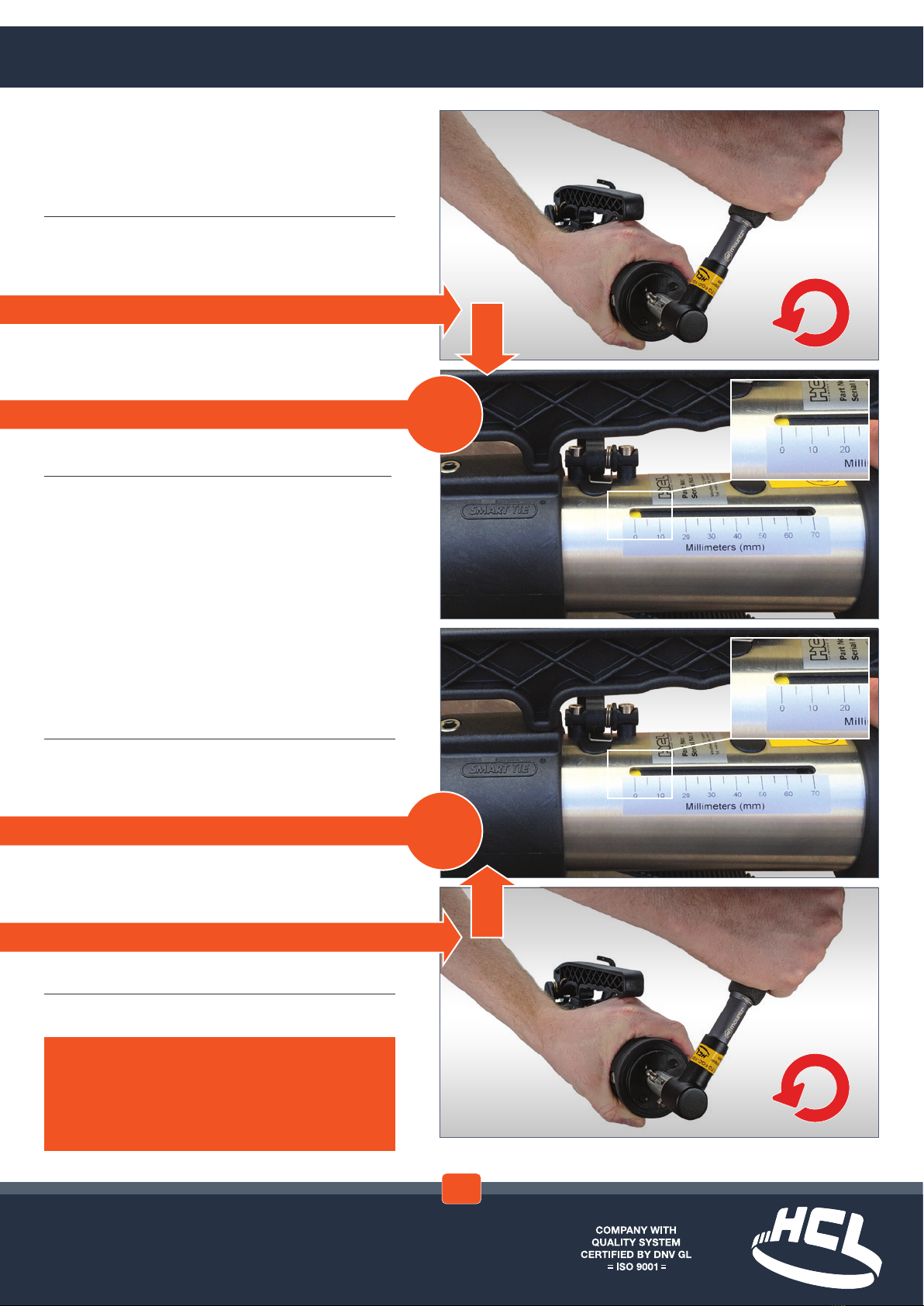
Tighten the band using a winding movement...
...until the Torque wrench ‘CLICKS’
6
Is yellow marker in the ‘0mm’ position?
7
Insert tool onto band...
...and push tool up against buckle
NOTE – The Mountz torque wrench is factory
set to the correct torque requirement for the
specied product being used. The set torque is
marked on the wrench.
The torque wrench does not have a ratchet
facility and will wind clockwise until the set
torque is reached. At this point it will slip over
with a positive click.
NO
YES
CLICK!
Operation - Using the Tool with Mountz Torque Wrench
IMPORTANT – If Mountz type torque wrench is
being utilised follow steps 6-9 followed by 18-20
NO
Go to 6.1
on next
page
YES
Go to 8.1
on next
page
3.1
www.hclfasteners.com
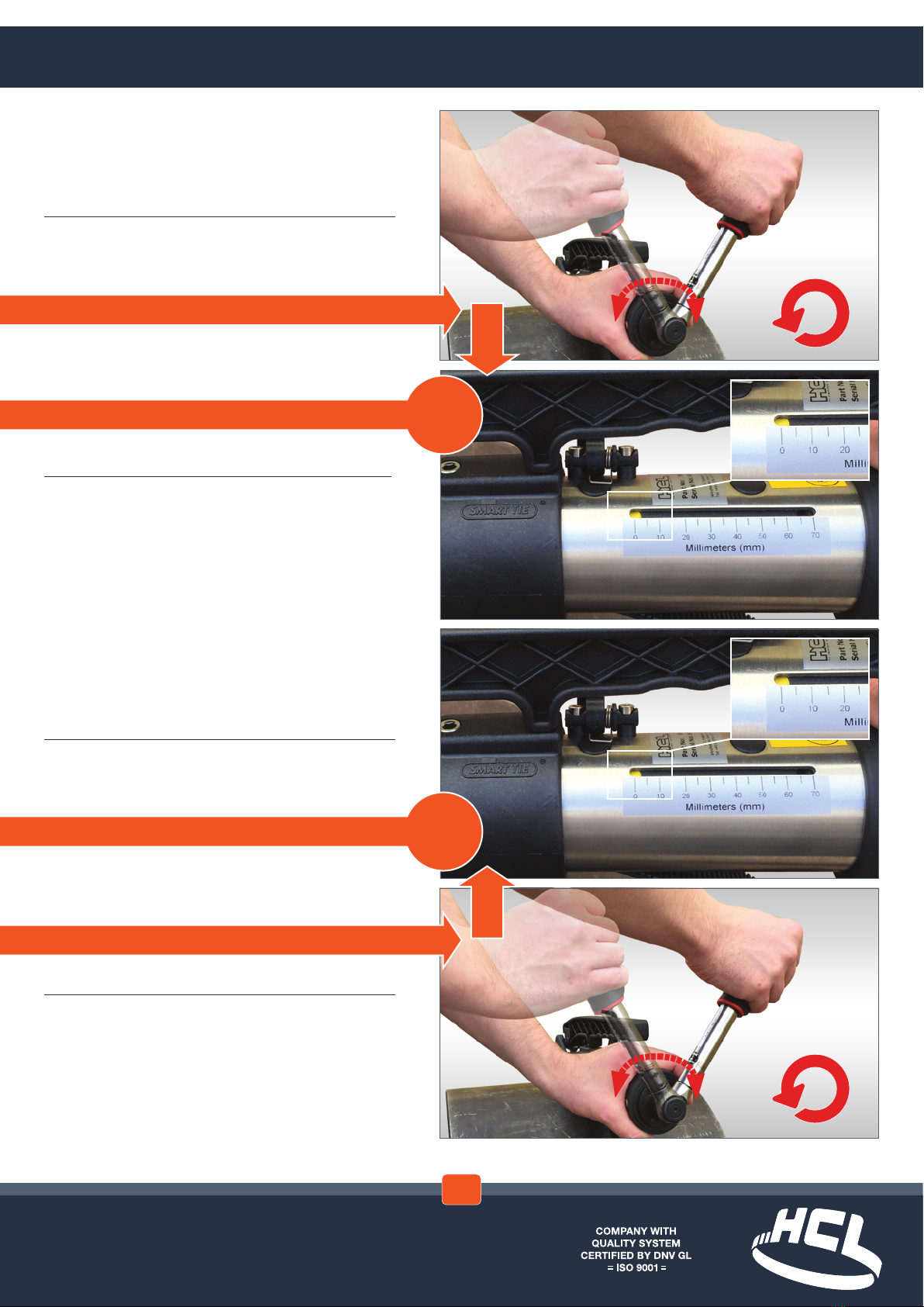
8.2
...until the yellow marker is at the
‘0mm’ position...
8.1
...wind Torque wrench anti-clockwise...
6.1
...wind Torque wrench anti-clockwise...
6.2
...until the yellow marker is at the
‘0mm’ position...
NOTE – In the aniti-clockwise direction, the
torque wrench will click over if enough
resistance is met. This could be experienced if
the tool is forced when reaching the end of its
travel at the ‘0mm’ position.
Go to 7
on previous
page
Go to 8
on previous
page
3.1

www.hclfasteners.com
3.1

www.hclfasteners.com
12
Set Torque Wrench to the required Torque
Refer to the tensioning tables in the
torque setting section for the maximum
recommended torque. See
torque wrench manual for
detailed operating instructions.
For reference the maximum
torque settings for each
material are labelled on the tool
and torque wrench.
13
Attach Torque wrench to the square drive at
the rear of the tool.
Optional – Lock Torque wrench to square drive
using a 4mm hexagon key
10
Wrap band around the application...
...and insert band into other end of buckle
11
Pull band tight by hand, making sure teeth are
fully engaged with band
WARNING – Do not exceed the maximum torque
settings recommended for the Smart®Tie or
Smart®Band system being applied
Operation - Using the Tool with Norbar Torque Wrench
3.1
IMPORTANT – If Norbar type torque wrench is
being utilised follow steps 10-20 and refer to the
torque setting section.
www.hclfasteners.com
17
Is the yellow marker in the ‘70mm’ position
(tool has run out of movement)?
16
Tighten the band using a ratcheting
movement...
...until the Torque wrench ‘CLICKS’
14
Is yellow marker in the ‘0mm’ position?
15
Insert tool onto band...
...and push tool up against buckle
WARNING – Do not wind the Torque wrench
using a smooth continuous movement or
beyond the click point
NO
YES
CLICK!
Operation - Using the Tool with Norbar Torque Wrench
3.1
NO
Go to 14.1
on next
page
YES
Go to 17.1
on next
page
www.hclfasteners.com
17.2
...until the yellow marker is at the
‘0mm’ position...
17.1
...wind Torque wrench anti-clockwise...
14.1
...wind Torque wrench anti-clockwise...
14.2
...until the yellow marker is at the
‘0mm’ position...
3.1
Go to 14
on previous
page
Go to 16
on previous
page

www.hclfasteners.com
19
To remove the excess band, simply take hold
of the cutting handle...
...and push upwards
20
Once cut, remove tool from buckle
Installation is now complete
18
Continue anti-clockwise rotation until the
yellow marker is in the ‘0mm’ position. At this
point the cutting clasp will release the cutting
handle.
Operation - Using the Tool
3.1

www.hclfasteners.com
Nm
kg-m lb-ft
x 1.36x 9.802
x 0.738x 0.102
x 7.23
x 0.138
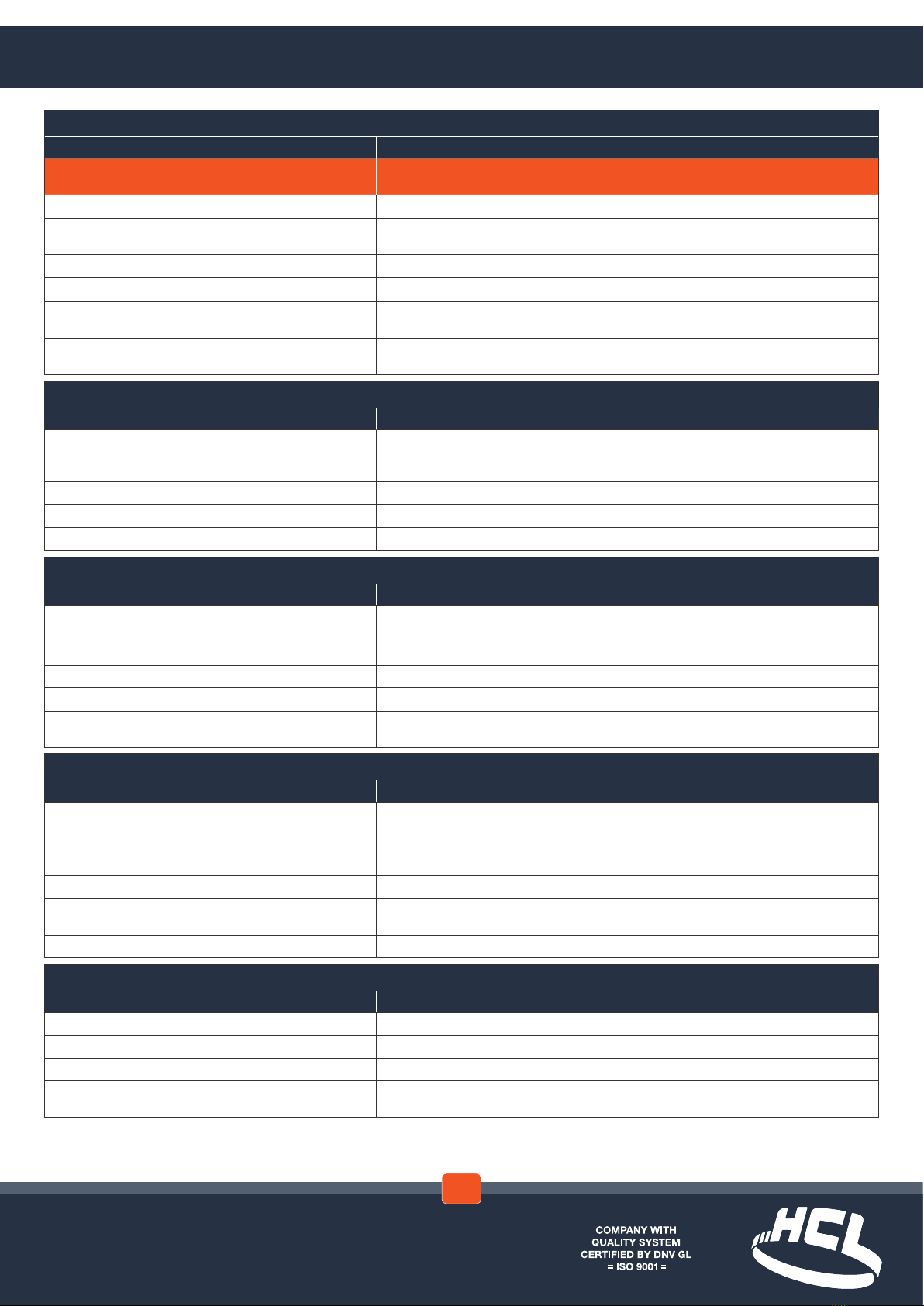
Recommended Torque Settings
*IMPORTANT – From July 2019 a new low torque drive system has been incorporated into the tool giving lower torque
settings than previous tools*
Smart®Tie Diameter Max Input Torque1Max System Force
(During Tightening)
Min Retention Force
(After Tightening)
Size Material mm Nm lb-ft N kgf lbf N kgf lbf
20mm (¾˝)
PA66 (Nylon 6.6)
100
5.5 4.1 3600 367 809 1500 153 337
PA12 (Nylon 12) 4 3.0 3000 306 674 1100 112 247
PK 5 3.7 3600 367 809 1500 153 337
PPS 5 3.7 3400 347 764 1500 153 337
32mm (1¼˝)
PA66 (Nylon 6.6)
200
TBC TBC TBC TBC TBC TBC TBC TBC
PA12 (Nylon 12) 8 6.0 6000 612 1349 2500 255 562
PK 11 8.1 7000 714 1574 4000 408 899
PPS 8 6.0 5500 561 1236 2000 204 450
Smart®Band Hybrid & Smart®Band Compact Diameter Max Input
Torque1
Max System Force
(During Tightening)
Min Retention Force
(After Tightening)
Size Buckle Material Band Material mm Nm lb-ft N kgf lbf N kgf lbf
19mm (¾˝)
PA66 (Nylon 6.6.) PA66 (Nylon 6.6.)
600
7 5.2 6000 612 1349 2500 255 562
PA12GF (Nylon 12 Glass-lled) PA12GF (Nylon 12 Glass-lled) 8 5.9 7000 714 1574 3500 357 787
PPS PPS 8 5.9 7000 714 1574 3500 357 787
POM (Acetal) POM (Acetal) 7 5.2 6000 612 1349 2500 255 562
32mm (1¼˝)
PA66 (Nylon 6.6.) PA66 (Nylon 6.6.) 14 10.3 14000 1428 3147 7000 714 1574
PA12GF (Nylon 12 Glass-lled) PA12GF (Nylon 12 Glass-lled) 14 10.3 14000 1428 3147 7000 714 1574
PPS PPS 14 10.3 12000 1224 2698 7000 714 1574
POM (Acetal) POM (Acetal) 10 7..4 10000 1020 2248 5000 510 1124
1The input torque in the table above is the maximum recommended torque around a cylindrical application. This may need to be reduced depending on the following:
- An irregular shaped application, e.g. an application that has sharp corners around its prole
- An application in high ambient temperatures and direct sunlight, where the temperature of the Smart®Band or Smart®Tie exceeds 40°C
- An application where the Smart®Band buckle is suspended in mid-air, i.e the buckle is not supported underneath
WARNING – The SM-FT-1000 tool range is not suitable for Smart® Band Standard systems. Do not exceed
the maximum torque settings recommended for the Smart®Tie or Smart®Band system being applied
Torque
Conversion
Triangle
Torque Setting - Smart® Band Hybrid & Compact
Note – This section is only required if the Norbar torque wrench is being utilised.
3.2
www.hclfasteners.com
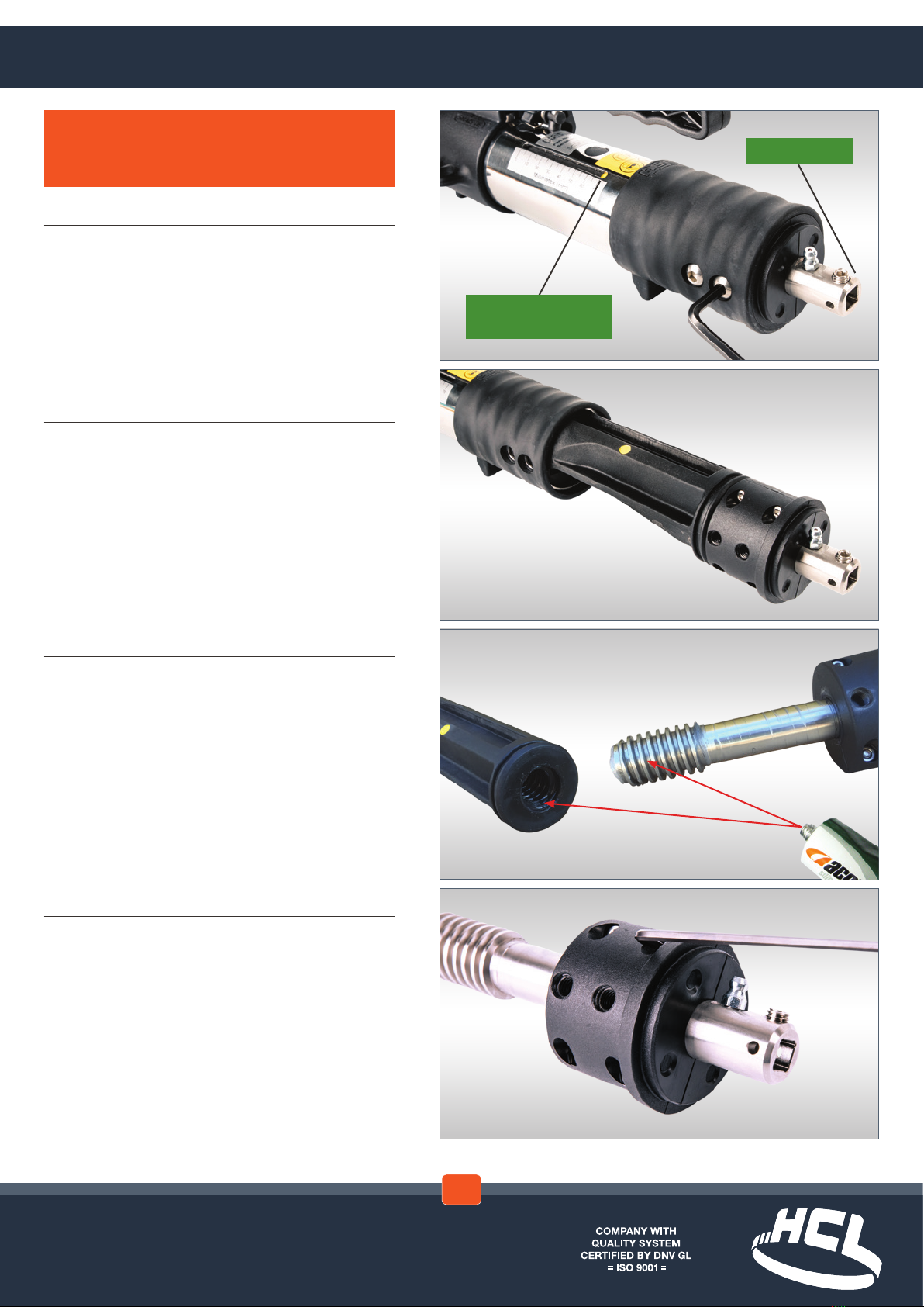
5
Wind the square drive anti-clockwise to
remove threaded shaft from internal housing.
Thoroughly clean all parts.
Apply a general grease suitable
for water contact to male and female threads
as shown
6
Remove M4 Capscrews and Full nuts
(4x each) from split housing. Thoroughly clean
all parts
1
Wind the square drive clockwise until yellow
marker is in the ‘70mm’ position
2
Tap square drive on rear of tool to ensure rear
housing is as far forward as possible (this will
aid the removal of the bolts)
3
Remove M8 Buttonhead screws (4x) using
5mm hexagon key
4
Remove internal sub-assembly
YELLOW MARKER IN
‘70mm’ POSITION
SQUARE DRIVE
Servicing
NOTE – It is advised that a full service is carried
out after every 1000 straps or every year, which
ever is soonest
4.1

www.hclfasteners.com
7
Apply a general grease suitable for water
contact to thrust washers and split housing as
shown
8
Change the Pawl and Blade by rstly removing
the Pin from the Pawl housing
NOTE – Take care to note the orientation of the
spring for reinsertion
9
Remove the Pawl assembly and spring
10
Reassemble Pawl Housing as reverse of
disassembly
Servicing
4.1

www.hclfasteners.com
14
Reassemble tool as reverse of disassembly
12
Ensure cutting handle is in the down position.
Remove Capscrews (4x) using 3mm hexagon
key and remove old front plate
13
Remove existing blade and insert spring into
new blade. Grease Cam and Blade as shown
WARNING – Care must be taken when handling
the sharp blade to avoid injury
15
If the tool has been used subsea it is advised
that it is immediately washed thoroughly by
immersing in clean fresh water. A full service is
advised in this situation. However, if this is not
possible the main thread can be lubricated via
the grease nipple located on the main shaft at
the rear of the tool
11
To take off the cutting blade housing, remove
M6 Capscrew and slide front assembly off
main body. Thoroughly clean all parts
NOTE – Never store the tool wet
Servicing
4.1
www.hclfasteners.com
Symptom 1: Smart®Band or Smart® Tie failure during tting
Failure Mode & Possible Cause Solution
1. System breaks due to cutting whilst in tension
(yellow marker not in ‘0mm’ position)
Do not operate cutter during tightening (Refer to Section 2.1, steps 12-14)
2. Band/Buckle breaks due to incorrect input torque Set correct input torque (Refer to Section 2.2, Tensioning Tables)
3. Buckle breaks due to incorrect tool positioning during tting Ensure tool is correctly positioned in buckle. Do not lift tool away from application during tightening
(Refer to Section 2.1, steps 8-9)
4. Band breaks due to repeated relaxing and re-tightening Only tighten the band once (Refer to Section 2.1, step 10)
5. Band pulls out of xed end of buckle Ensure that latch is fully engaged with band before tensioning (Refer to Section 2.1, step 2)
6. Buckle breaks due to being positioned in mid-air or around too
small a radius
Position Buckle on suitable radius (Refer to Banding Products Technical Booklet). Reduce the input
torque if re-positioning is not possible
7. Band breaks due to being positioned around too small a radius Position Buckle on suitable radius (Refer to Banding Products Technical Booklet). Reduce the input
torque if re-positioning is not possible
Symptom 2: Inadequate Smart®Band or Smart®Tie tension
Possible Cause Solution
1. Tool has hit rear stop (yellow marker in ‘70mm’ position) Wind square drive anti-clockwise until yellow marker is in ‘0mm’ position. Then continue
tightening the band (Refer to Section 2.1, step 11). Then continue tightening the band until the Torque
wrench ‘CLICKS’
2. Input torque incorrect Set Torque Wrench to correct torque (Refer to Section 2.2, Tensioning Tables)
3. Tool requires servicing Service tting tool (Refer to Section 4.1, steps 1-9)
4. Tool under performing (lack of tension) after subsea use Clean & lubricate tool (Refer to Section 4.1)
Symptom 3: Tool does not grip Smart®Band or Smart®Tie
Possible Cause Solution
1. Excess band tail too short Remove band and replace with a longer length
2. Pawl housing not fully forward (yellow marker not in
‘0mm’ position)
Wind square drive anti-clockwise until yellow marker is in ‘0mm’ position (Refer to Section 2.1, step 11)
3. Pawl teeth dirty or clogged Remove internal sub-assembly from tool and clean pawl teeth (Refer to Section 4.1, steps 1-4)
4. Incorrect pawl tted Remove pawl and replace with correct size for band (Refer to Section 3.1, steps 1-3)
5. Pawl stuck in position Remove internal sub-assembly from tool and un-stick pawl (Refer to Section 4.1, steps 1-4). Clean and
re-grease pawl and ensure free movement
Symptom 4: Smart®Band or Smart®Tie does not feed through tool
Possible Cause Solution
1. Blockage in tool, e.g. band Remove internal sub-assembly or front sub-assembly as required, then clear blockage (Refer to Section
4.1, steps 1-4)
2. Pawl stuck in position Remove internal sub-assembly from tool and un-stick pawl (Refer to Section 4.1, steps 1-4). Clean and
re-grease pawl and ensure free movement
3. Pawl Housing not fully forward (green marker not showing) Wind square drive anti-clockwise until yellow marker is in ‘0mm’ position (Refer to Section 2.1, step 11)
4. Blade stuck down Remove and clean blade. Front end may need to be removed. Be careful that blade does not spring out
(Refer to Section 3.2, steps 1-3)
5. Incorrect front end is tted Remove front end and replace with correct one (Refer to Section 3.2, steps 1-3)
Symptom 5: Tool does not cut or it is too dicult to cut
Possible Cause Solution
1. Blockage in tool, e.g. band Remove blade and/or front end as required, then clear blockage (Refer to Section 3.2, steps 1-3)
2. Cam not lubricated (blade may also make ‘screeching’ noise) Grease cam and blade (Refer to Section 4.1, step 9)
3. Blade worn or damaged Replace or re-sharpen blade (Refer to Section 3.2, steps 1-3)
4. Incorrect blade or front end is tted Remove blade and/or front end and replace with correct size for band (Refer to Section 3.2,
steps 1-3)
Servicing - Troubleshooting
4.2
www.hclfasteners.com
20
21
23
3
1
36
2517 26
12
16
15 13 4 18 19
14
22
11
29
30
27
32
28
37 5 8 9 7 10 6 2
31
35
33
34
24
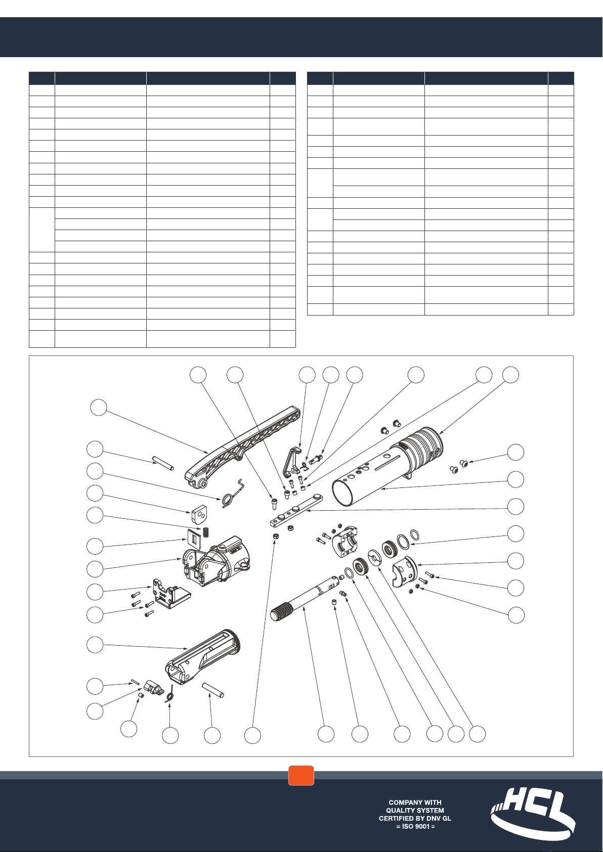
ITEM PART NUMBER DESCRIPTION QT Y.
1 PRT1002 HOUSING, MAIN BODY 1
2 PRT1003 GRIP, OVERMOULDED, FITTING TOOL 1
3 PRT1004 GUIDE 1
4 NUT_NYLOC_HEX_M6_SS NUT, NYLOC, HEXAGON, M6, SS 2
5 CPS_M6X10_SS CAPSCREW, SKT HD, M6x10LG, SS 1
6 PRT1341 SPACER, PIVOT PIN PROTOTYPE 2
7 PRT1340 PIN, PIVOT 1
8 PRT1339 CLASP, CUT PREVENTION 1
9 PRT1342 SPRING, TORSION 1
10 CPS_M4X12_SS CAPSCREW, SKT HD, M4x12LG, SS 2
11 PRT1035 HOUSING, PAWL 1
12*
PRT1036 PAWL, 32mm 1
PRT1055 PAWL 19mm SMART BAND 1
PRT1297 PAWL 20mm SMART TIE 1
PRT1338 PAWL 32mm SMART TIE 1
13 PRT1037 PIN, Ø10x54LG 1
14 PRT1038 PIN, Ø3x20LG 1
15 PRT1039 SPRING, TORSION 1
16 PRT1502 BEARING 1
17 PRT1041 MAIN SHAFT, THREADED 1
18 THB_20_35_10_SS BEARING, THRUST, BALL, 20IDx35ODx10LG 2
19 PRT1058 WASHER, FLAT, 12IDx35ODx4LG 2
20 WAS_WAVE_2670_3432_124 WASHER, WAVE SPRING,
26.70IDx34.32ODx1.24LG 1
ITEM PART NUMBER DESCRIPTION QT Y.
21 PRT1045 HOUSING, THRUST BEARING 2
22 NUT_HEX_M4_SS NUT, FULL, HEXAGON, M4, SS 4
23 CPS_M4X16_SS CAPSCREW, SKT HD, M4x16LG, SS 4
24 ORG_01872X262_BS116_N70A O-RING, BS116, 18.72IDx2.62CS, NITRILE 70A 2
25 SSS_M8X8_CUP_SS SKT SETSCREW, M8x8LG, CUP POINT, SS 2
26 GN_M6_STRAIGHT_SS GREASE NIPPLE, STRAIGHT, SS 1
27 PRT1046 HOUSING, CUTTING BLADE 1
28 PRT1295 FRONT END, CAST, 32mm, CHAMFERED SLOT 1
PRT1296 FRONT END, CAST, 19mm & 20mm 1
29 CPS_M4X16_SS CAPSCREW, SKT HD, M4x16LG, SS 4
30 PRT1048 BLADE, CUTTING, 32mm 1
PRT1057 BLADE, CUTTING 19mm & 20mm 1
31 PRT1049 SPRING, COMPRESSION 1
32 PRT1050 LEVER, CUTTING MECHANISM 1
33 PRT1051 CAM, ROLLER 1
34 PRT1052 PIN, Ø8x55LG 1
35 PRT1503 HANDLE RETURN SPRING 1
36 BHS_M8X10_SS BUTTONHEAD SCREW, SKT HD, M8x10LG, SS 4
37 CPS_M6X16_SS CAPSCREW, SKT HD, M6x16LG, SS 1
*Item 12 is either Smart® Tie 20mm (¾˝), Smart® Tie 32mm (1¼˝), Smart® Band 19mm (¾˝) or
Smart® Band 32mm (1¼˝) option.
Items 28 & 30 are either 19mm or 32mm options (20mm Smart® Tie tool uses 19mm option).
Servicing - Parts List
4.3


Considerable effort has been made to ensure that this product conforms to our high quality standards. However, should you
experience any diculties, please contact your Sales representative providing samples and the serial code specied on the tool.
Name of manufacturer: HCL Fasteners Ltd
Address of manufacturer: Clamping House, First Avenue, Westeld Industrial Estate, Radstock,
Bath BA3 4BS, UK
Telephone: +44 (0)1761 417714
Email: [email protected]
Machinery description: Banding tool for tensioning the HCL Smart® Tie 20mm (¾˝),
Smart® Tie 32mm (1¼˝), Smart® Band 19mm (¾˝) Hybrid & Compact or
Smart® Band 32mm (1¼˝) Hybrid & Compact Systems
Tool Size: Smart® Tie 20mm (¾˝)
Smart® Tie 32mm (1¼˝)
Smart® Band 19mm (¾˝) Hybrid & Compact
Smart® Band 32 mm (1¼˝) Hybrid & Compact
Serial No:
HCL – UK & Rest of the World
Tel: +44 (0)1761 417714
Fax: +44 (0)1761 417710
HCL – North America
Tel: +1 281-717-1145
Fax: +1 281-717-1146
Email: [email protected]
Visit www.hclfasteners.com to view our complete range of products.
March 2021
©HCL Fasteners. All Rights Reserved.
Other manuals for Smart Band SM-FT-1000
1
Table of contents
Other HCL Tools manuals


