HCL Smart Band SM-FT-1000 Instruction Manual

TOOLING
©2009 HCL Fasteners
Operation, Parts and
Safety Manual
SM-FT-1000
Banding Tool
Suitable for Smart Band® 32mm (1¼”) 25mm (1”)
19mm (¾”) and Smart Tie™ 20mm (¾”)
READ ALL INSTRUCTIONS BEFORE OPERATING THIS
HCL PRODUCT
IMPORTANT – DO NOT DESTROY
It is the customer’s responsibility to have all operators
and servicemen read and understand this manual.
For additional copies please contact HCL.
Registered
NOVEMBER 2009
TOOLING
©2009 HCL Fasteners
Operation, Parts and
Safety Manual
1 Warning & Safety Instructions
2 Introduction
3 Operation
4 Tensioning Tables
5 Pressure Regulation
6 Maintenance
7 Adapting the Tool
8 Trouble Shooting
9 Parts List
NOVEMBER 2009

SM-FT-1000 Banding Tool
BANDING TOOLING
Warning Read these instructions carefully
Whilst the composite Smart Band® is considered significantly
safer than alternative metallic solutions, failure to follow these
instructions can still result in personal injury.
General safety considerations:
1. STRAP BREAKAGE HAZARD Smart Band® is free from sharp metallic edges however it is
important to understand that improper operation of the tool or
sharp corners on the load can result in strap breakage during
tensioning that could result in the following:
– A sudden loss of balance causing you to fall
– Both tool and strap flying violently towards your face
Failure to place the strap properly around the load, an unstable or
shifted load, could result in a sudden loss of strap tension during
tensioning. This could result in a sudden loss of balance causing
you to fall.
Positioning yourself in-line with the strap during tensioning, can
result in personal injury from flying strap or tool. When tensioning,
position yourself to one side of the strap and keep all bystanders
away.
2. TRAINING This tool must not be used by persons not properly trained
in its use. Be certain that you receive proper training from
your employer. If you have any questions contact your HCL
representative.
3. EYE INJURY HAZARD Failure to wear safety glasses with side shields can result in eye
injury or blindness. Always wear safety glasses with side shields
which conform to ANSI Standard Z87.1 or EN 166.
4. FALL HAZARD Maintaining improper footing and/or balance when operating the
tool can cause you to fall. Do not use the tool when you are in an
awkward position.
5. CUT HAZARD Although the Smart Band® is not metallic and therefore
significantly less likely to cause cuts to hands or fingers it is still
strongly recommended that the operator wear protective gloves.
6. NOISE HAZARD When using the pneumatic option, ear protection is
recommended.
7. TOOL CARE – Inspect and clean the tool daily. Replace all worn or broken
parts
– Lubricate all moving parts approximately every 50 hours of use
– On air powered tools always disconnect the pneumatic
connection to the tool when performing part removal and
replacement procedures. NEVER connect a pneumatic source to
a disassembled tool unless otherwise specified
– If used in sea water, wash off with fresh water after use.
8. WORK AREA Keep work areas uncluttered and well lit.
(for further information
see maintenance section)
SECTION 1

BANDING TOOLING
Introduction
SM-FT-1000 Banding Tool
Depending on set up, this power tool is designed
to assemble HCL Smart Band® 32mm (1¼”),
25mm (1”), 19mm (¾”) or Smart Tie™ 20mm (¾”)
Systems.
Follow the instructions described to achieve safe
operation.
SM-FT-1000 Banding Tool
WATERPROOF CASE
MAIN FITTING TOOL
REGULATOR
5M HOSE
WINDING HANDLE
TORQUE WRENCH
AIR RATCHET
W2300 / W2301
AIR RATCHET W2303
MANUAL CUTTER
SECTION 2

BANDING TOOLING
SM-FT-1000 Banding Tool
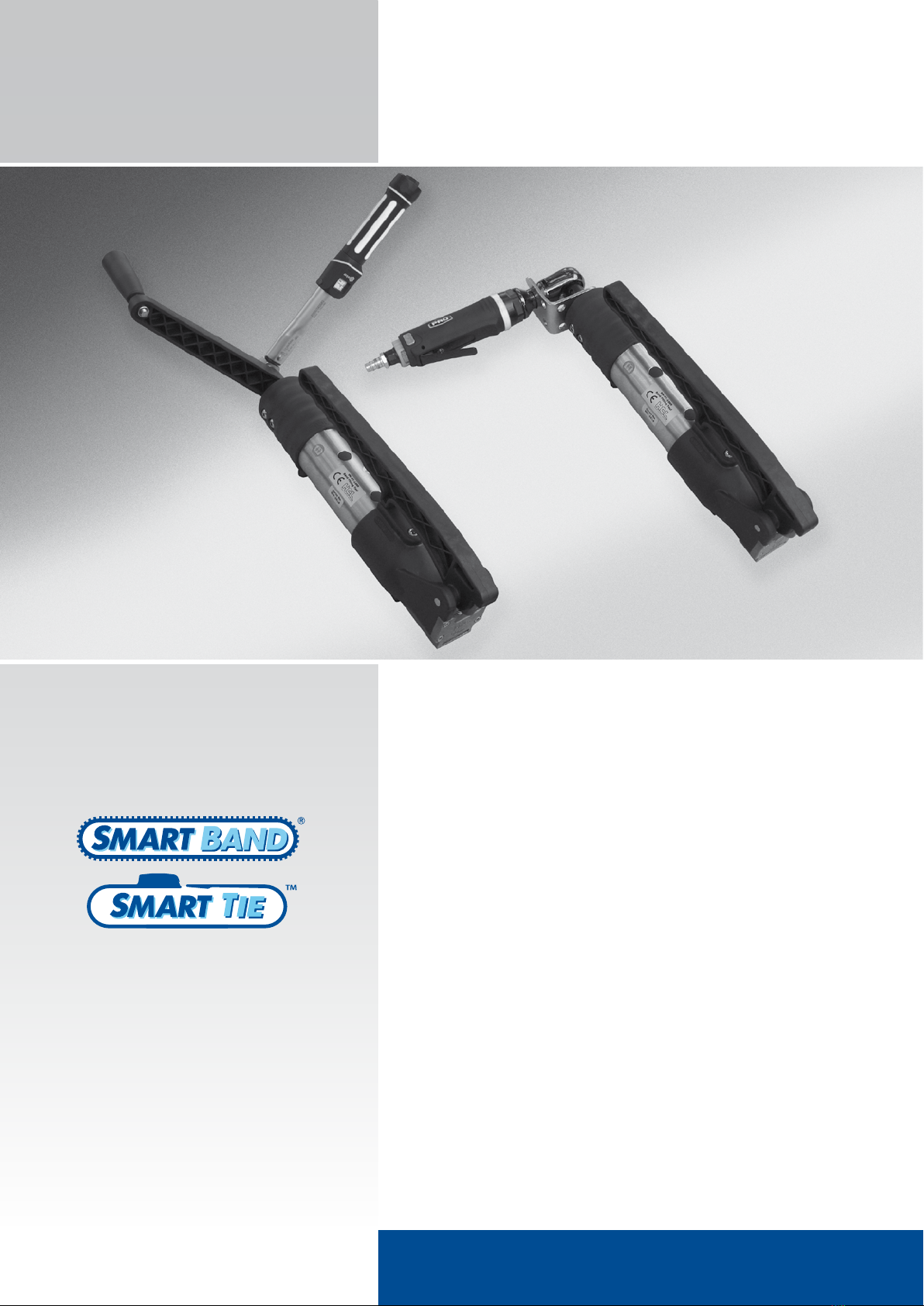
1
Insert band into fixed end of
the buckle
3
Wrap band around the
application
4
Insert band into other end of
buckle
Operation
Initial fitting and tightening
2
Pull back band to engage latch
WARNING – Ensure latch is
fully engaged with band before
tightening. Latch not fully engaged
could lead to premature failure of
system when tightening
TEETH ENGAGED
SECTION 3
BANDING TOOLING
SM-FT-1000 Banding Tool
5
Pull band tight by hand, making
sure teeth are fully engaged
with band
6
Ensure that green marker is
showing
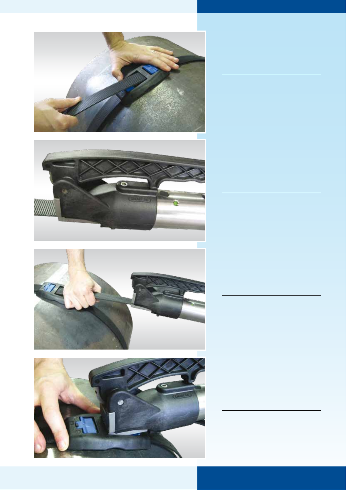
7
Insert tool onto band
8
Push tool up against buckle
SECTION 3
BANDING TOOLING
11
To gain high accuracy in tension
fit using torque wrench. Refer to
the tensioning tables to set the
correct torque
See torque wrench manual for
detailed operating instructions
NOTE – Torque wrench can be
used without handle using the
socket provided
12
For pneumatic tightening
attach air ratchet to the square
drive at the rear of the tool
and locate in torque reaction
bracket
See air ratchet manual for
detailed operating instructions
SM-FT-1000 Banding Tool
10
Wind handle clockwise until
band is tight. If red marker is
showing, wind handle anti-
clockwise until green, then
continue to tighten the band
GREEN MARKER -
Indicates tool is at
the start of its travel
RED MARKER –
Indicates tool is at the
end of its travel
SECTION 3
9
For manual tightening attach
handle to the square drive at
the rear of the tool
WARNING – Ensure tool does not
lift away from application
during tightening
WARNING – Do not operate the
Cutter during tightening
(see step 14)
....
BANDING TOOLING
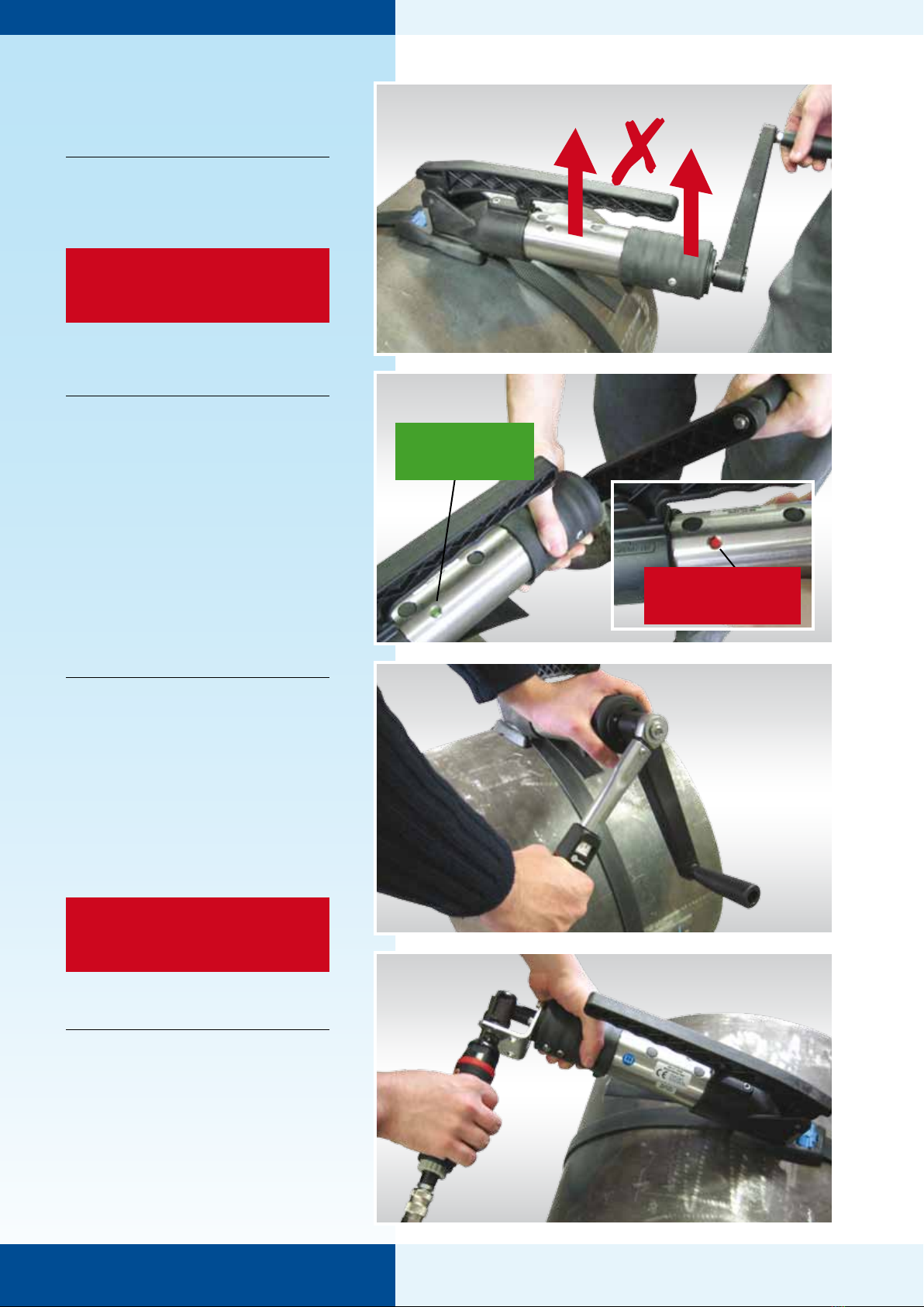
13
Refer to Section 4 Tensioning Tables to
set the correct pressure.
Hold down trigger on air ratchet. The
tool will stall when the system reaches
the correct tension. If red marker is
showing, simply reverse direction of
tool by turning knob on back of air
ratchet head (see inset). Wind tool back
until green, reverse direction again and
continue to tighten.
If required, further calibration can be
achieved with a torque wrench see
photo 11
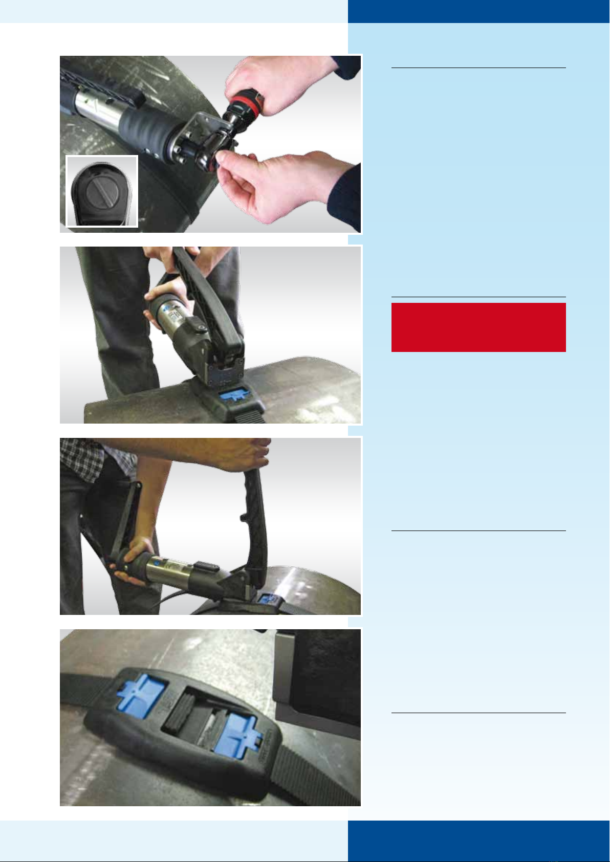
14
WARNING – Ensure that the green
marker is showing before cutting
the band.
To remove the excess band,
simply take hold of the cutting
handle...
15
...and push upwards
16
Once cut remove tool from
buckle – Installed system
SM-FT-1000 Banding Tool
SECTION 3
BANDING TOOLING
SM-FT-1000 Banding Tool
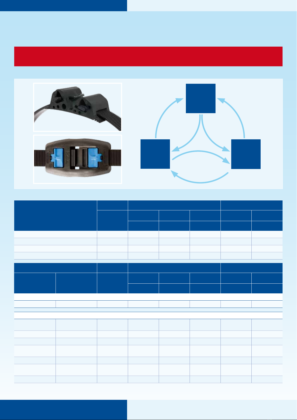
Tensioning Tables
WARNING – Do not exceed the maximum pressure or torque settings recommended for the
Smart Tie™ or Smart Band® system being applied
Pressure Conversion Triangle
MPa
(N/mm2)
Psi
(lb/in2)Bar
x 0.1x 0.006895
x 10x 145.03
x 0.06895
x 14.503
Recommended setting for each system
Smart Tie™
System Width Maximum Recommended Input 1System Force 2
(mm) / (inch)
Torque Wrench 3Air Ratchet
W2303
Air Ratchet
W2300 / W2301
Max. during
Fitting
Min. Final
Retention
Torque (Nm) Pressure (MPa) Pressure (MPa) (N) (N)
PP (Polyproylene) 20 / ¾– 0.3 – 1500 700
PA66 (Nylon 66) 20 / ¾– TBC – TBC TBC
PA11 (Nylon 11) 20 / ¾– 0.3 – 2600 1700
POM (Acetal) 20 / ¾– 0.35 – 3400 1800
Smart Band® System Width Maximum Recommended Input 1System Force 2
Head Material Band Material (mm) / (inch)
Torque Wrench 3
13042
Air Ratchet
W2303
Air Ratchet
W2300 / W2301
Max. during
Fitting
Min. Final
Retention
Torque (Nm) Pressure (MPa) Pressure (MPa) (N) (N)
Standard Buckle – see photo above
PA66 (Nylon 66) POM (Acetal) 25 / 1 8 0.33 – 5600 2000
Hybrid Buckle – see photo above
PA11GF
(Nylon 11 Glass Filled)
PA11GF
(Nylon 11 Glass Filled) 19 / ¾13 0.45 – 8200 3400
POM (Acetal) POM (Acetal) 19 / ¾11 0.40 – 7100 3000
PA66 (Nylon 66) PA66 (Nylon 66) 19 / ¾14 0.50 – 8600 3700
PA11GF
(Nylon 11 Glass Filled)
PA11GF
(Nylon 11 Glass Filled) 25 / 1 14 0.45 – 9200 4500
PA11 (Nylon 11) PA11 (Nylon 11) 25 / 1 12 0.40 – 7100 4000
PA11GF
(Nylon 11 Glass Filled)
PA11GF
(Nylon 11 Glass Filled) 32 / 1¼30 – 0.45 17500 8000
POM (Acetal) POM (Acetal) 32 / 1¼22 – 0.35 13500 5000
1] IMPORTANT – Tightening force may need to be reduced depending upon application and environment
2] The larger the diameter, the closer the final retention will be to the maximum tension induced upon fitting
3] Using the torque wrench increases the repeatability accuracy
Standard Buckle
Hybrid Buckle
SECTION 4
BANDING TOOLING
SM-FT-1000 Banding Tool
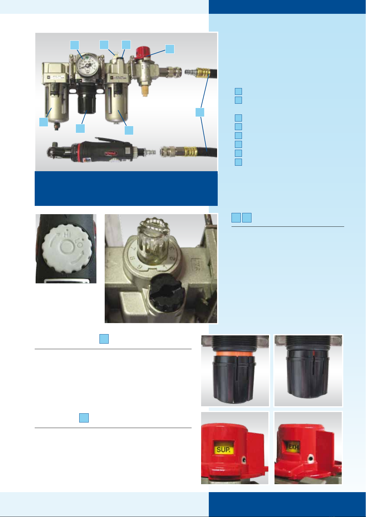
Pressure
Regulation
1 Pressure Regulator Gauge
2 Air Filter – 3/8” BSP female
input
3 Pressure Regulator Knob
4 Air Lubricator
5 Lubrication Dial
6 Lubrication Fill-point
7 Lockable Shut-Off Valve
8 5m hose
4
5 6 7
8
3 Pressure Regulator
To set required pressure, pull down Pressure
regulator knob until orange band appears,
then twist until dial shows required pressure,
finally, click knob back up until orange band
disappears.
7 Lockable Shut-Off Valve
Set Lockable shut-off valve to ‘SUP.’ to supply
air to the tool. To shut-off the air supply to the
tool and dump the excess pressure in the hose
to atmosphere, set Lockable shut-off valve to
‘EXH.’ (this enables safe removal of the hose).
Air Lubricator
To fill lubricator, remove black cap
using 5mm Allen key and fill to
between the maximum and minimum
oil levels. See air ratchet manual for
suitable oils. Ensure lubricator dial is
set to ‘2’ at all times.
5 6
IMPORTANT – Input pressure should be greater than
0.6 MPa but less than 1.0 MPa
– Input hose size should be ½” and above
SECTION 5
1
23
Ensure Pressure Dial
on Ratchet Wrench
is set to ‘HI’ at all
times
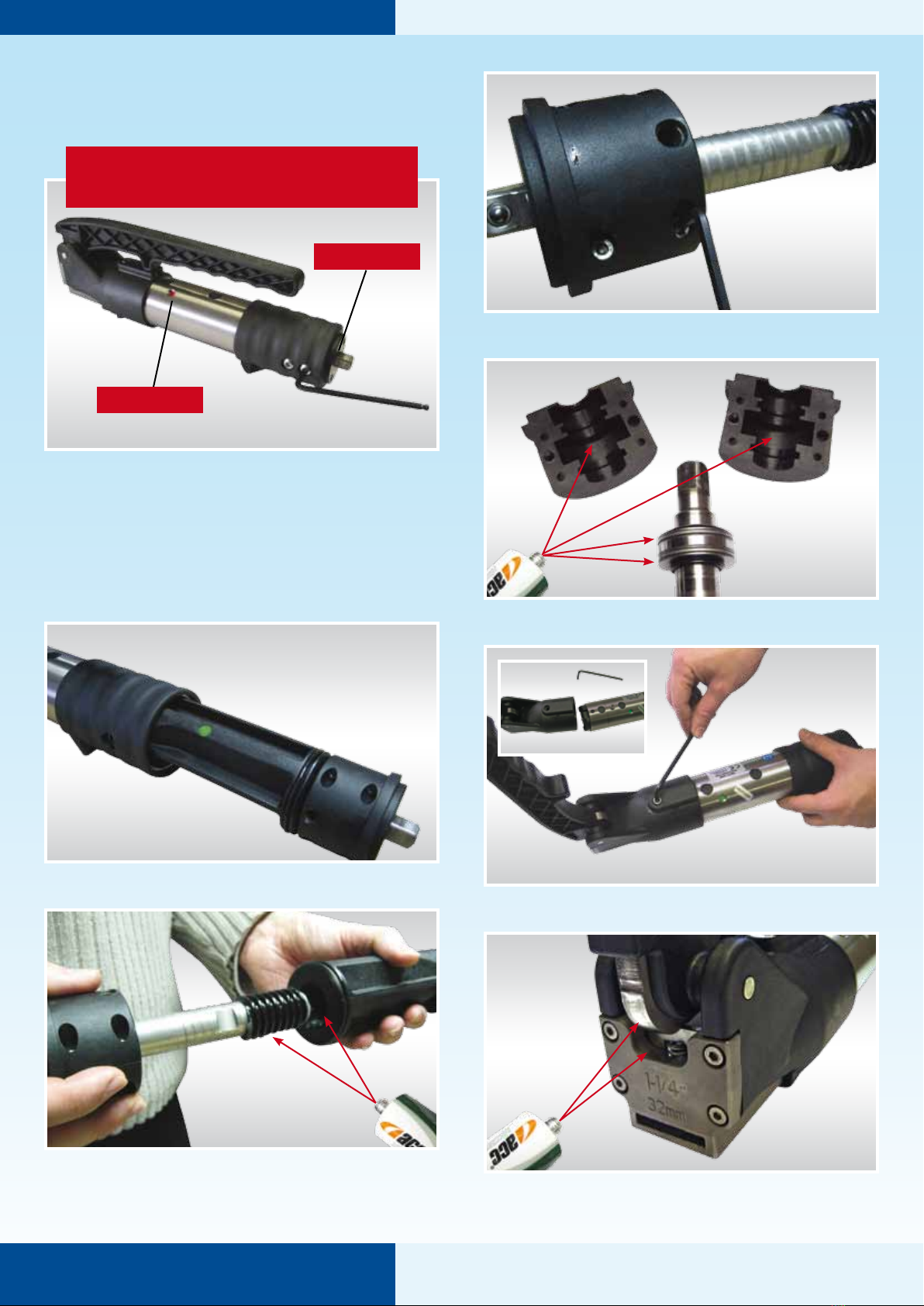
Maintenance
SM-FT-1000 Banding Tool
BANDING TOOLING
1 Wind the square drive clockwise until red marker is
showing
2 Tap square drive on rear of tool to ensure rear housing is
as far forward as possible. This will aid the removal of the
bolts
3 Remove M8 Buttonhead screws (4x) using 5mm Allen key
RED MARKER
TOOL BACK
For maintenance of air ratchets please
see manufacturers manual
SECTION 6
4 Remove internal sub-assembly
5 Wind the square drive anti-clockwise to remove threaded
shaft from internal housing. Thoroughly clean all parts.
Apply Silicone grease to male and female threads as
shown
6 Remove M4 Capscrews and Full nuts (4x each) from split
housing. Thoroughly clean all parts
7 Apply Silicone grease to thrust washers and split housing
as shown
8 Remove M6 Capscrew and slide front assembly off main
body. Thoroughly clean all parts
9 Grease Cam and blade as shown
BANDING TOOLING
SM-FT-1000 Banding Tool
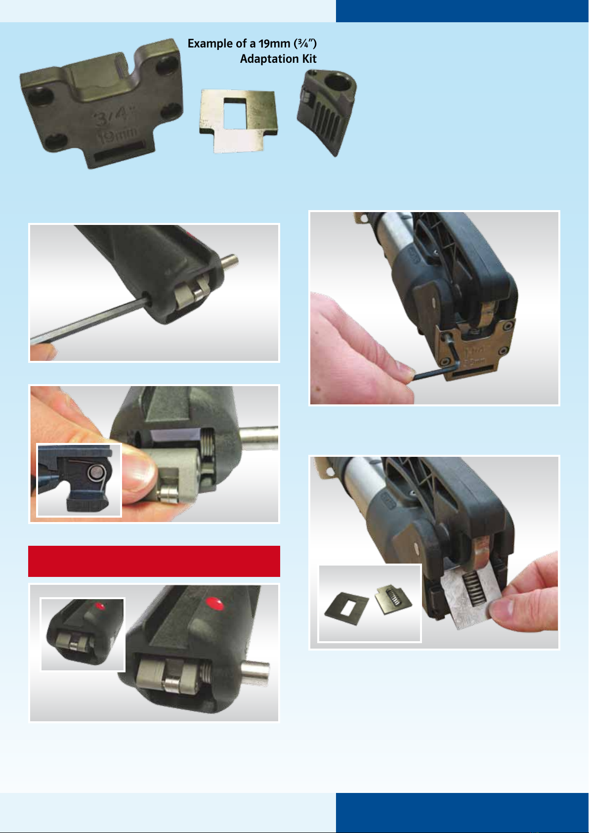
Adapting
the Tool
Every fitting tool can be adapted to fit
the following sizes of Smart Band:
32mm (1¼”), 25mm (1”) & 19mm (¾”)
Example of a 19mm (¾”)
Adaptation Kit
SECTION 7
Changing the Pawl
5 Remove pin from housing
6 Remove old pawl and insert new pawl
7 Re-fit pin. Reassemble tool as reverse of disassembly
Changing the Front Plate & Blade
1 Ensure cutting handle is in the down position. Remove
Capscrews (4x) using 3mm Allen Key and remove old front
plate
2 Remove existing blade and insert spring into new blade
3 Reassemble tool as reverse of disassembly
1-4 Repeat steps 1-4 in Section 6, Maintenance
NOTE – Take care to reinsert spring in correct
orientation.

SM-FT-1000 Banding Tool
BANDING TOOLING SECTION 8
Trouble Shooting
Symptom 1: Inadequate Band Tension
Possible Cause Solution
1. Tool has hit rear stop (red marker showing) Wind square drive anti-clockwise until green marker is showing. Then continue tightening the
band (Refer to Section 3, Operation; steps 10 & 13)
2. Input torque incorrect (Hand tool) Set Torque Wrench to correct torque (Refer to Section 4, Tensioning Tables)
3. Input pressure incorrect (Air tool) Check supply pressure. Set regulator to correct pressure. Set Air Ratchet to ‘HI’ (Refer to Section 4,
Tensioning Tables and Section 5, Pressure Regulation)
4. Torque reaction bracket incorrect or not in use Fit torque reaction bracket to rear of fitting tool. Ensure that air ratchet fits tightly into bracket
(Refer to Section 3, Operation; steps 12 & 13)
5. Tool requires servicing Service fitting tool (Refer to Section 6, Maintenance)
Symptom 2: Tool does not grip Band
Possible Cause Solution
1. Excess band tail too short Remove band and replace with a longer length
2. Pawl housing not fully forward (green marker not showing) Wind square drive anti-clockwise until green marker is showing. Then continue tightening the
band (Refer to Section 3, Operation; steps 10 & 13)
3. Pawl teeth dirty or clogged Remove internal sub-assembly from tool and clean pawl teeth (Refer to Section 6, Maintenance;
steps 1-4)
4. Incorrect pawl fitted Remove pawl and replace with correct size for band (Refer to Section 7, Adapting the Tool)
5. Pawl stuck in position Remove internal sub-assembly from tool and un-stick pawl (Refer to Section 6, Maintenance;
steps 1-4)
Symptom 3: Band does not feed through Tool
Possible Cause Solution
1. Blockage in tool, e.g. band Remove internal sub-assembly or front sub-assembly as required, then clear blockage (Refer to
Section 6, Maintenance, steps 1-4 & 8)
2. Pawl stuck in position Remove internal sub-assembly from tool and un-stick pawl (Refer to Section 6, Maintenance;
steps 1-4)
3. Pawl Housing not fully forward (green marker not showing) Wind square drive anti-clockwise until green marker is showing (Refer to Section 3, Operation;
steps 10 & 13)
4. Blade stuck down Remove and clean blade. Front end may need to be removed. Be careful that blade does not
spring out (Refer to Section 7, Adapting the Tool)
5. Incorrect front end is fitted Remove internal sub-assembly from tool and un-stick pawl (Refer to Section 6, Maintenance;
steps 1-4)
Symptom 4: Tool does not cut or it is too difficult to cut
Possible Cause Solution
1. Blockage in tool, e.g. band Remove blade and/or front end as required, then clear blockage (Refer to Section 7, Adapting the
Tool)
2. Cam not lubricated (blade may also make ‘screeching’ noise) Grease cam and blade (Refer to Section 6, Maintenance; step 9)
3. Blade worn or damaged Replace or re-sharpen blade (Refer to Section 7, Adapting the Tool)
4. Incorrect blade or front end is fitted Remove blade and/or front end and replace with correct size for band (Refer to Section 7,
Adapting the Tool)
Symptom 5: Smart Band Failure during fitting
Failure Mode & Possible Cause Solution
1. Band/Buckle breaks due to incorrect input torque or pressure Set correct input torque or pressure (Refer to Section 4, Tensioning Tables)
2. Buckle breaks due to incorrect tool positioning during fitting Ensure tool is correctly positioned in buckle. Do not lift tool away from application during
tightening (Refer to Section 3, Operation; steps 8-9)
3. Band breaks due to repeated relaxing and re-tightening Only tighten the band once (Refer to Section 3, Operation; step 10)
4. System breaks due to cutting whilst in tension (green
marker not showing)
Do not operate cutter during tightening (Refer to Section 3, Operation; step 14)
5. Band pulls out of fixed end of buckle Ensure that latch is fully engaged with band before tensioning (Refer to Section 3, Operation;
step 2)
6. Buckle breaks due to being positioned in mid-air or around
too small a radius
Position Buckle on suitable radius (Refer to Banding Products Technical Booklet; Section 2.2
Technical – Installation Design)
7. Band breaks due to being positioned around too small a
radius
Position Band on suitable radius (Refer to Banding Products Technical Booklet; Section 2.2
Technical – Installation Design)

BANDING TOOLING
Parts List
SM-FT-1000 Banding Tool
SECTION 9
1
2
3
4 5
6
7
8
9
10 11 12
13 14 15
16
17 18 19
20
21
22
23
24
25
26
27
28
29
30 31
32
ITEM PART NUMBER DESCRIPTION QTY.
1 BHS_M8X10_SS BUTTONHEAD SCREW, SKT HD,
M8x10LG, SS 4
2 BLB_3_7_3_SS BEARING, BALL ROLLER, 3IDx7ODx3LG 2
3 CPS_M4X16_SS CAPSCREW, SKT HD, M4x16LG, SS 8
4 CPS_M6X10_SS CAPSCREW, SKT HD, M6x10LG, SS 1
5 CPS_M6X16_SS CAPSCREW, SKT HD, M6x16LG, SS 1
6 NUT_HEX_M4_SS NUT, FULL, HEXAGON, M4, SS 4
7 NUT_NYLOC_HEX_M6_SS NUT, NYLOC, HEXAGON, M6, SS 2
8 ORG_01872X262 O-RING, 18.72IDx2.62CS, NITRILE 70A 2
9 PRT1044 PLUNGER, BALL SPRING 1
10 PRT1002 HOUSING, MAIN BODY 1
11 PRT1003 GRIP, OVERMOULDED, FITTING TOOL 1
12 PRT1004 GUIDE 1
13 PRT1035 HOUSING, PAWL 1
14
PRT1036 PAWL, 32mm 1
PRT1040 PAWL, 25mm 1
PRT1040 PAWL, 19mm 1
15 PRT1037 PIN, Ø10x54LG 1
16 PRT1038 PIN, Ø3x20LG 1
17 PRT1039 SPRING, TORSION 1
18 PRT1041 MAIN SHAFT, THREADED 1
19 PRT1045 HOUSING, THRUST BEARING 2
20 PRT1046 HOUSING, CUTTING BLADE 1
ITEM PART NUMBER DESCRIPTION QTY.
21
PRT1047 FRONT END, CAST, 32mm 1
PRT1053 FRONT END, CAST, 25mm 1
PRT1054 FRONT END, CAST, 19mm 1
22
PRT1048 BLADE, CUTTING, 32mm 1
PRT1056 BLADE, CUTTING, 25mm 1
PRT1057 BLADE, CUTTING, 19mm 1
23 PRT1049 SPRING, COMPRESSION 1
24 PRT1050 LEVER, CUTTING MECHANISM 1
25 PRT1051 CAM, ROLLER 1
26 PRT1052 PIN, Ø8x55LG 1
27 PRT1059 WASHER, FLAT, 12IDx35ODx4LG 1
28 PRT1059 BOLT, SQUARE DRIVE 1
29 SSS_M8X35_CUP_PT_SS SKT SETSCREW, M8x35LG, CUP
POINT, SS 1
30 THB_20_35_2 BEARING, THRUST, NEEDLE ROLLER,
20IDx35ODx2LG 2
31 WAS_FLAT_20_35_1 WASHER, FLAT, 20IDx35ODx1LG 4
32 WAS_WAVE_2670_3432_124 WASHER, WAVE SPRING,
26.70IDx34.32ODx1.24LG 1
* Items 14, 21 & 22 are either 19mm, 25mm or 32mm options

Your attention is drawn to the following:
HCL warrants that a new HCL banding tool will operate per functional specifications for a period of sixty (60) days after the date of
shipment to the owners place of business. Normal wearing parts, as outlined in the Operations, Parts & Safety manual, are also covered
by a sixty (60) day warranty unless, in HCL’s judgement, these parts have been subjected to abnormal or extreme usage. HCL’s sole
liability hereunder will be to repair or replace, without charge, F.O.B. HCL, Bath UK, any tool which proves to not operate per functional
specifications within the stated period. HCL reserves the right to replace any tool which proves not to operate per functional specifications
with a new or like-new tool of the same model, if in HCL’s judgement such replacement is appropriate. Any new replacement or like new
replacement tool provided to an owner will carry a full sixty (60) day warranty. Any warranty repaired tool will carry a warranty for the
balance of time remaining on the initial sixty (60) day warranty. This warranty will be extended to compensate for the time the tool is in
HCL’s possession for warranty repairs.
This warranty is void as to any tool which has been:
a) subjected to mis-use, misapplication, accident damage, or repaired with other than genuine HCL replacement parts.
b) improperly maintained, or adjusted, or damaged in transit or handling.
c) used with improperly filtered, regulated, unlubricated air.
d) in HCL’s opinion, altered in a way that affects or detracts from the performance of the tool.
HCL MAKES NO WARRANTY, EXPRESSED OR IMPLIED, RELATING TO MERCHANTABILITY, FITNESS OR OTHERWISE EXCEPT AS STATED
ABOVE AND HCL’S LIABILITY AS ASSUMED ABOVE IS IN LIEU OF ALL OTHERS ARISING OUT OF OR IN CONNECTION WITH THE USE
AND PERFORMANCE OF THE TOOL. IT IS EXPRESSLY UNDERSTOOD THAT HCL SHALL IN NO EVENT BE LIABLE FOR ANY INDIRECT OR
CONSEQUENTIAL DAMAGES INCLUDING, BUT NOT LIMITED TO, DAMAGES WHICH MAY ARISE FROM LOSS OF ANTICIPATED PROFITS OR
PRODUCTION, SPOILAGE OF MATERIALS, INCREASED COSTS OF OPERATION OR OTHERWISE.
Considerable effort has been made to ensure that this product conforms to our high quality standards. However, should you
experience any difficulties, please contact your Sales representative providing samples and the serial code specified on the tool.
Declaration
of Conformity
Name of manufacturer: HCL Fasteners Ltd
Address of manufacturer: First Avenue, Westfield Industrial Estate, Radstock, Bath BA3 4BS, UK
Telephone: +44 (0)1761 417714
Email [email protected]
I hereby declare that the following machinery complies with all the Essential Health and Safety
Requirements of the Machinery Directive 89/392/EEC as amended.
Machinery description: Banding tool for tensioning the HCL Smart Band® 32 mm (1¼”),
25mm (1”), 19mm (¾”) or Smart Tie™ 20mm (¾”) Systems
Type: Banding Tool SM-FT-1000
Serial No:
Transposed Harmonised European Standards used:
BS EN 12100 – 1&2:2003 Safety of Machinery – Basic concepts, general principles for design
prEN 983 Safety requirements for fluid power systems and components –
Pneumatics
EN 349 : 1993 Safety of Machinery – Minimum gaps to avoid crushing of parts of the
human body
BS EN 792-10 Hand-held non-electric power tools – Safety requirements – Part 14:
Compression power tools
HCL Fasteners Limited, Registered Office: First Avenue, Westfield Industrial Estate, Radstock, Bath, BA3 4BS United Kingdom.
Tel: +44 (0)1761 417714 Fax: +44 (0)1761 417710 www.hclfasteners.com
Other manuals for Smart Band SM-FT-1000
1
Table of contents
Other HCL Tools manuals


