manuals.online logo
Brands
  1. Home
  2. •
  3. Brands
  4. •
  5. JAMEC PEM
  6. •
  7. Tools
  8. •
  9. JAMEC PEM PRO X EXTREME-RETRACTABLE User manual

JAMEC PEM PRO X EXTREME-RETRACTABLE User manual

OPERATING INSTRUCTIONS
PRODUCT NO.
58.3012 - 20 meter X 10 mm (3/8") Air Hose Pro X Extreme - Retractable
58.3023 - 30 meter X 10 mm (3/8") Air Hose Pro X Extreme - Retractable
58.3034 - 20 meter X 10.5 mm (1/2") Water Hose Pro X Extreme - Retractable
58.3045 - 30 meter X 10.5 mm (1/2") Water Hose Pro X Extreme - Retractable
AIR & WATER HOSE REEL
PRO X EXTREME - RETRACTABLE
AIR & WATER HOSE REEL
PRO X EXTREME - RETRACTABLE
The Jamec Pem Air Hose Pro X Extreme - Retractable has been manufactured
using the highest quality materials. This multi-purpose hose reel is suitable for
compressed air and water applications and is ideal for use around the home,
automotive workshop or industrial site.
FEATURES
Controlled hose return
Stop anywhere hose control
Hose layering system
Auto lock / auto rewind
No tools required adjustable hose stop
Wall mount with 180° pivot with self cantering
Weather resistant UV stabilised polypropylene case
Leader hose 2 m with brass ttings
Solid brass internal spindle (AIR HOSE REEL ONLY)
Includes water trigger gun (WATER HOSE REEL ONL)
Includes Jamec Pem Extreme Ultraex Hose
INSTALLATION
The Jamec Pem Air Hose Pro X Extreme - Retractable can be mounted in a vertical
position.
1. Chose a location that is near to the water source or compressed air source.
2. For large areas, place the hose reel at the centre of the work area.
3. When mounting the hose reel, ensure there is adequate clearance under the reel
to prevent injury or damage.
0.8 METRE MIN.
Fig. 1 Mounting Bracket
Fig. 2 Pivot Pin
1
6
5
2
4
3
7
4. Mounting bracket must be installed on a at surface.
Note: It is recommended to install the mounting bracket 0.8
metre (minimum) above the oor level.
5. Drill 4 x M8 holes to match the holes located in the
Mounting Bracket.
(Fig. 1)
6. Connect the hose reel to the Mounting Bracket with the
Pivot Pin.
(Fig. 2)
7. Connect the inlet leader hose to the source using the
ttings supplied.
Note: Apply thread sealing tape to all air line and air hose
ttings.
SPECIFICATIONS AIR HOSE AIR HOSE
Part no. 58.3012 58.3023
Hose length 20 m 30 m
Hose I.D 9.2 mm (3/8") 9.2 mm (3/8")
Hose O.D 15.2 mm (5/8") 15.2 mm (5/8")
Leader hose length 2 m with 1/4” BSP Male tting 2 m with 1/4" BSP Male tting
Hose material Extreme Ultraex Reinforced Hose Extreme Ultraex Reinforced Hose
Reel / case type Retractable / polypropylene Retractable / polypropylene
Auto lock / rewind Yes Yes
Stop anywhere function Yes Yes
Controlled hose return Yes Yes
Adjustable tension control Yes Yes
Replaceable hose Yes Yes
Max. working pressure 300 psi 300 psi
Fitting size 1/4" BSP Male 1/4" BSP Male
Bracket 180° Pivoting 180° Pivoting
Weight - kg 9.5 9.5
Product dimensions 604.2 L x 275.1 W x 430.5 D mm 604.2 L x 275.1 W x 430.5 D mm
Advised application Air Air (long reach)
SPECIFICATIONS WATER HOSE WATER HOSE
Part no. 58.3034 58.3045
Hose length 20 m 30 m
Hose I.D 10.5 mm (1/2") 10.5 mm (1/2")
Hose O.D 16.5 mm (5/8") 16.5 mm (5/8")
Leader hose length 2 m with brass tap ttings 2 m with brass tap ttings
Hose material Extreme Ultraex Reinforced Hose Extreme Ultraex Reinforced Hose
Reel / case type Retractable / polypropylene Retractable / polypropylene
Auto lock / rewind Yes Yes
Stop anywhere function Yes Yes
Controlled hose return Yes Yes
Adjustable tension control Yes Yes
Replaceable hose Yes Yes
Max. working pressure 150 psi 150 psi
Fitting size 12 mm Tap ttings 12 mm Tap ttings
Bracket 180° Pivoting 180° Pivoting
Weight - kg 9.5 9.5
Product dimensions 604.2 L x 275.1 W x 430.5 D mm 604.2 L x 275.1 W x 430.5 D mm
Advised application Water Water (long reach)
PRODUCT IDENTIFICATION
1. Mounting bracket
2. Fully enclosed case
3. Carry handle
4. Brass internal spindle (nylon internal spindle water model)
5. 2 metre leader hose
6. Hose with Adjustable Stopper
7. Water Gun (with water model only)
ADJUSTING THE STOP-BALL
The location of the hose stopper can be adjusted to allow more hose or less hose to
be exposed when fully rewound.
1. Pull out the desired length of hose, ensuring the hose reel is in the lock position.
2. Open the latch on the hose stopper and move it to the desired position on the hose.
3. Re-latch the hose stopper at desired position
CAUTION:
Always make sure the hose reel is in the locked position before removing the hose
stopper and make sure the hose stopper is securely fastened before unlocking the
reel.
ADJUSTING THE TENSION SPRING
Over time it is natural for the spring to lose some
tension. The tension can easily be adjusted and
tightened to provide years of service.
CHANGING THE HOSE
1. Release all tension on the hose prior to
commencing. See section “ADJUSTING THE
SPRING TENSION”.
OPERATION
1. Slowly pull out the hose to the required length. A ‘click’ noise will be heard. To
lock the reel, allow the hose to retract slowly after hearing ‘click’.
2. To release the hose, pull out the hose until you hear a ‘click’, and then allow the
hose to slowly retract while guiding the hose back into the hose reel. The self
layering mechanism will coil the hose back onto the inner drum.
3. To avoid injury and damage, always hold the hose while it is retracting. This hose
reel has a controlled return function which allows the hose to return slowly if it is
let go. It is always recommended to always hold the hose while it’s retracting. In
the event the hose is let go this controlled return function will stop the hose from
reacting too fast.
IMPORTANT:
IF THE HOSE BECOMES TANGLED AND WILL NOT RETRACT - SLOWLY PULL
OUT THE HOSE PAST THE TANGLED
SECTION AND THEN ALLOW THE HOSE TO
SLOWLY RETRACT WHILE GUIDING THE HOSE BACK INTO THE HOSE REEL.
ALWAYS ENSURE THE HOSE IS CLEAN AND NOT TWISTED.
CAUTION:
Only adjust the spring when the hose is fully rewound. Do Not Over-tighten
4.
Using a at head screw driver, remove the side cover marked “Coil Spring
Adjustment” by prying it open where indicated.
5. Fold out the crank handle.
6. Turn the crank clockwise to increase
the tension, counter clock-wise to reduce the tension.
7. Turn the crank handle ve times in the desired direction. Check the spring
tension by pulling a short length of the hose and letting it rewind.
8. Repeat this process until there is just enough tension to fully rewind the hose
9. The hose tension should only to tensioned to the point where the hose stopper
“just” makes it back to the hose reel. If the hose is returning to hard and fast to
the hose reel then the tension is too much and needs to be adjusted accordingly.
(Over tensioning will not be covered by warranty)
DO NOT OVER TENSION THE SPRING. DOING SO WILL NOT ALLOW THE HOSE TO
BE PULLED OUT ENTIRELY AND MAY RESULT IN DAMAGE TO THE HOSE REEL
AND SPRING MECHANISM
2. Note that all the hose needs to be pulled
out from the hose reel prior to commencing.
So the procedure in point 1 will
have to be done several times as the spring tension will increase as the hose is
extracted.
3. Once all the hose has been pulled out move to point 3.
NOTE: DO NOT ATTEMPT TO CHANGE THE HOSE WHILE ANY TENSION ON THE
SPRING EXISTS. DOING SO CAN CAUSE INJURY.
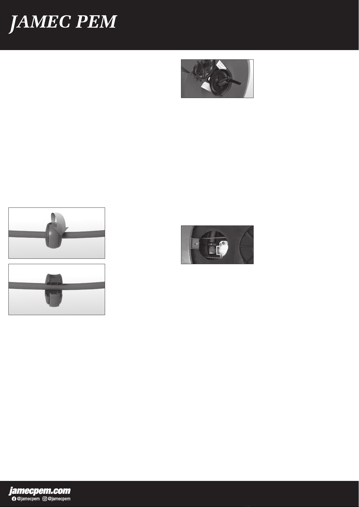
4. Using a at head screw driver, remove the side cover marked “cover removal”
by prying it open where indicated. (this cover is the same side as the inlet side of
the hose reel.
5. Move the internal drum until you expose the hose connection window on the
internal drum. Use a small spanner / screw driver to undo the hose clamp.
Remove hose from barded hose connection on the internal drum and feed hose
out of the hose reel.
6. Feed new hose through the roller guide onto the barbed hose connection on the
internal drum. Retighten the hose clamp.
7. Replace the inlet side cover.
8. Re-tension the spring by following the section “ADJUSTING THE SPRING
TENSION”.
9. As the spring gets more tension the hose will automatically retract back into
the hose reel. Once hose has completely retracted into the hose reel, adjust the
tension on the spring accordingly.
DO NOT OVER TENSION THE SPRING. DOING SO WILL NOT ALLOW THE HOSE
TO BE PULLED OUT ENTIRELY AND MAY RESULT IN DAMAGE TO THE HOSE
REEL AND SPRING MECHANISM.
MAINTENANCE
Always keep the hose clean.
If the hose becomes dirty, clean it with a damp cloth while retracting.
DO NOT twist the hose while in use.
Mount the hose reel in a sheltered area to assist and protect the performance of
the hose and hose reel.
DO NOT allow the hose to contact any corrosive chemicals or uids.
Always retract the hose when not in use.
The JamecPem PRO:X Hose Reel contains a pre-tensioned spring inside the
inner drum assembly. Do not attempt to open the inner drum assembly.
WARRANTY & CLAIM PROCEDURE
The amec Pem Air Hose Pro X Extreme - Retractable is covered against defects in
material and workmanship.
In the instance of a warranty claim, the owner will be entitled to a replacement unit
or a sufcient repair of the defective part/s and or component/s to ensure normal
operating condition of the hose reel.
WARRANTY EXCLUSIONS
The hose, rubber o-rings and hose stopper are deemed normal wear items and are
not covered under warranty.
The warranty does not extend to parts or components affected or damaged by
accident, normal wear, misuse, neglect or faulty installation.
To register a warranty claim visit: jamecpem.com
Distributed by
TRADEPEM INDUSTRIAL PTY LTD.

This manual suits for next models

4

Other JAMEC PEM Tools manuals

JAMEC PEM 11.0534 User manual

JAMEC PEM

JAMEC PEM 11.0534 User manual

JAMEC PEM PRO Series User manual

JAMEC PEM

JAMEC PEM PRO Series User manual

JAMEC PEM PRO EXTREME Series User manual

JAMEC PEM

JAMEC PEM PRO EXTREME Series User manual

JAMEC PEM PRO Series User manual

JAMEC PEM

JAMEC PEM PRO Series User manual

JAMEC PEM PRO Series User manual

JAMEC PEM

JAMEC PEM PRO Series User manual

JAMEC PEM PRO:X User manual

JAMEC PEM

JAMEC PEM PRO:X User manual

JAMEC PEM PRO Series User manual

JAMEC PEM

JAMEC PEM PRO Series User manual

JAMEC PEM 58.0201 User manual

JAMEC PEM

JAMEC PEM 58.0201 User manual

JAMEC PEM PRO Series User manual

JAMEC PEM

JAMEC PEM PRO Series User manual

JAMEC PEM PRO Series User manual

JAMEC PEM

JAMEC PEM PRO Series User manual

Popular Tools manuals by other brands

BorMann PRO Series user manual

BorMann

BorMann PRO Series user manual

FOOTAGE C200 owner's manual

FOOTAGE

FOOTAGE C200 owner's manual

Ingersoll-Rand 2DA Series Operation and maintenance manual

Ingersoll-Rand

Ingersoll-Rand 2DA Series Operation and maintenance manual

Westfalia 40 67 93 instruction manual

Westfalia

Westfalia 40 67 93 instruction manual

Black & Decker RT 650 Original instructions

Black & Decker

Black & Decker RT 650 Original instructions

Meister FW260M Original instructions

Meister

Meister FW260M Original instructions

P.A. M63PA ATEX Maintenance handbook

P.A.

P.A. M63PA ATEX Maintenance handbook

Bosch GBH 12-52 D Original instructions

Bosch

Bosch GBH 12-52 D Original instructions

MSW MSW-ETTBMW-06 user manual

MSW

MSW MSW-ETTBMW-06 user manual

Pop ProSet 2500 Series Maintenance manual

Pop

Pop ProSet 2500 Series Maintenance manual

Powerfix Profi PKRS 1.5 A1 operating instructions

Powerfix Profi

Powerfix Profi PKRS 1.5 A1 operating instructions

MSW MSW-SPS-15 user manual

MSW

MSW MSW-SPS-15 user manual

Kellfri 27-EA52 manual

Kellfri

Kellfri 27-EA52 manual

Rose electronics PINPUSHER IV owner's manual

Rose electronics

Rose electronics PINPUSHER IV owner's manual

RASOR FP702 Use manual

RASOR

RASOR FP702 Use manual

Ryobi PCL540 Operator's manual

Ryobi

Ryobi PCL540 Operator's manual

CAPTELEC QUICK FIX instruction manual

CAPTELEC

CAPTELEC QUICK FIX instruction manual

BEA 554 DCC Spare parts list/service instructions

BEA

BEA 554 DCC Spare parts list/service instructions

manuals.online logo
manuals.online logoBrands
  • About & Mission
  • Contact us
  • Privacy Policy
  • Terms and Conditions

Copyright 2025 Manuals.Online. All Rights Reserved.