HE-VA Grass-Combi User manual

Manual no. 8000201-01 100320


Contents
EC DECLARATION OF CONFORMITY .......................................................................................................3
Delivery Check ..................................................................................................................................................3
Machine description...........................................................................................................................................4
Technical specifications...............................................................................................................................5
Safety around the Grass-Combi.........................................................................................................................5
Safety Instructions, regarding Hydraulic System ..............................................................................................6
Markings on the machine...................................................................................................................................6
Maintenance.......................................................................................................................................................7
Warning..............................................................................................................................................................8
Disposal..............................................................................................................................................................9
Noter ................................................................................................................................................................12
Spare parts list..................................................................................................................................................10
Main components.........................................................................................................................................10
Middle frame w/socket for Multi-Seeder.....................................................................................................13
Wing left 2 bars............................................................................................................................................14
Wing left 3 bars............................................................................................................................................16
Leveling bars................................................................................................................................................19
Platform foldable .........................................................................................................................................21
Step at Multi-Seeder ....................................................................................................................................22
Support wheel ..............................................................................................................................................23
Hydraulic..........................................................................................................................................................25
Folding and angel og tines...........................................................................................................................25
Extension hoses to a connected roller..........................................................................................................27
Notes................................................................................................................................................................28

EC DECLARATION OF CONFORMITY
in accordance with the EU Machinery Directive 2006/42/EC
applicable as from December 29th 2009:
HE-VA ApS
N. A. Christensensvej 34,
DK-7900 Nykøbing Mors
hereby confirms that the following machine has been manufactured in accordance with the Council
Directive 2006/42/EC.
The declaration comprises the following machines:
Grass-Combi with 2 or 3 bars for tines
6,0m hydraulic foldable
Nykøbing the 23rd March 2020 Villy Christiansen
The undersigned is furthermore authorised to compile technical documentation for the above machine.
Delivery Check

UK Grass-Combi 6,0m 2 and 3 bars 29-04-2020
4 Back to the table of contents
Check the Grass-Combi for any damage when it is received at either the dealer and the final customer.
Check that the frame construction has not beeb exposed to impacts. Check the air-pressure in the tires before
operating.
Check the hydraulic hoses for cuts and squeezing damages. Check also the other hydraulic components, are
not damaged during transport.
Machine description
The Grass-Combi is a 2 or 3 bar strigle which is suitable for aeration of pasture, and loosen crop residue for
faster degradation. The machine can only be delivered as a tail-mounted model.
The machine can only be mounted with one type of tines:
•Ø12 mm x 440 mm tines for aeration of pasture
Standard equipment:
•Adjustable wheels –4 pc. 18,5x8,5x8”
•2 or 3 hydraulic adjustable bars
•The individual angel between the bars are mechanically adjusted
Row spacing:
•2 bars: 9,0 cm
•3 bars: 9,0 cm
Distance between bars:
•2 bars: 300 mm
•3 bars: 330 mm

UK Grass-Combi 6,0m 2 and 3 bars 29-04-2020
5 Back to the table of contents
Technical specifications
Working
width
Bars
AC/EC
Transport width
Transport-
height
No. of
tines
HP
requirement
Weight in
kg
6,00m
hydr.
2
No
2480
3200
66
120-175
1600
2
Yes
2480
3200
66
120-175
1575
7,00m
hydr.
3
No
2480
3200
66
120-175
1750
3
Yes
2480
3200
66
120-175
1725
Tyre pressure
3,8 bar / 55 psi
Oil pressure
min. 150 bar
Hydraulic outlets
2 double acting
Quick couplings, standard
Sterling type E 402
Hydraulic oil: The machine is filled
with
Hydro Texaco HD32
Safety around the Grass-Combi
Do not operate the machine, if any people** are at risk in the dangerous area.*
When persons are at risk in the dangerous area (e.g. when doing adjustments, maintenance or connect or
disconnecting), the following points must be met:
•Lower the machine on solid ground.
•Hydraulics must be relieved.
•Tractor must be turned off, and the key removed.
•Driver must be aware of, when operating that there is no persons at risk in the dangerous area.
* Dangerous area: At the machine and underneath it, and in a distance of 4 m from it.
** People at risk: Any person, who is completely or partially in the dangerous area.
Most accidents when operating the machine, transporting and doing maintenance occurs, when avoiding the
most simple safety regulations.
For this reason, it is of highest importance, that any person who is operating the machine, strictly follows the
safety regulations and other instructions, which belongs the machine.
The machine must only be operated, maintained and fixed by persons, who is confidential with and skilled
for this work and is aware of moments of danger, which can occur.
ATTENTION!! Rotating parts and clothes in a loose condition, is a dangerous combination.
IMPORTANT!! It is strictly prohibited for any person to take place on the frame or chassis
of the machine, when it is either operating or the tractor is idling.

UK Grass-Combi 6,0m 2 and 3 bars 29-04-2020
6 Back to the table of contents
Instructions for transport at public roads:
Before transport at public roads, make sure that the attachment of the implement to the tractor, is in
accordance with the local rules and regulations in force (permitted total weight, permitted axel load,
transport width, lights and warning signs).
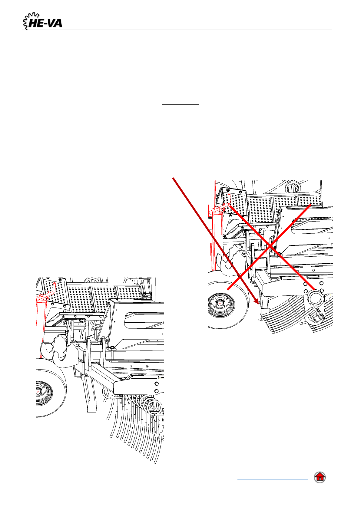
When driving at public roads, the tines must be folded towards the frame. This will reduce the width
of the machine substantially.
Front axel load:
When the implement is attached and at maximum load, the tractors driving properties must be ensured.
Check that the front axel is sufficiently loaded. The front axel load must be at least 20% of the tractors
weight. Permitted axel load and total weight for the tractor must be respected.
NB! The driving, controlling and braking properties are affected by the attached implement.
Safety Instructions, regarding Hydraulic System
•The highest allowable pressure, is 225 bar.
•It is recommended to mark the hydraulic connections between the implement and tractor, to avoid
incorrect operation!
•When checking for hydraulic leeks, suitable safety gear must be used due to danger. (Safety,
goggles, gloves, etc.)
At high pressure, hydraulic oil can penetrate the skin and course serious injuries.
•Before any work at the hydraulic system, the implement must be lowered to solid ground. Pressure
must be relieved, engine stopped, and ignition key removed.
•Check the hydraulic hoses on a regular basis, however, every six months as a minimum due to any
cracks, wear and tear, etc. Replace any defective hoses immediately.
•Hydraulic hoses lasts for no more than 5 years.
New hydraulic hoses must be identical to the manufacturers specifications.
Markings on the machine
Several markings are located at your machine, which contains safety regulations and other instructions to
inform about correct operating.
Please read these instructions carefully, and make the driver aware about the markings and safety
regulations in this Operating Instructions. Keep the markings clean and readable. If they are not, they must
be replaced.

UK Grass-Combi 6,0m 2 and 3 bars 29-04-2020
7 Back to the table of contents
Safety and other markings on the machine
Study the Operating Instructions thoroughly before any operation of
the machine and observe all safety instructions.
Plate with number and year of manufacture.
Take care that no persons are within the machine’s hazardous area
during the unfolding and folding procedure.
Maintenance
After 10 hours of operation, tightening of wheels, bearings and stop rings must be done. If this is not
respected our warranty will lapse.
Maximum torque in Nm. w/lubricated thread
Metric thread
Quality 8.8
Quality 10.9
Quality 12.9
M10x1,5
47
65
79
M12x1,75
81
114
136
M14x2,0
128
181
217
M16x2,0
197
277
333
M18x2,5
275
386
463
M20x2,5
385
541
649
M22x2,5
518
728
874
M24x3,0
665
935
1120
Hub bolts M18x1,5 fine thread
433 Nm
Hub bolts M22x1,5 fine thread
803 Nm

UK Grass-Combi 6,0m 2 and 3 bars 29-04-2020
8 Back to the table of contents
•Pins and bushings with lubrication nipples must be greased every 25 hours of operation.
•Eventually damages at the paint must be rapaired at least once in the season. This will preserve
and make the machine stay in a good condition for many years.
Warning
To avoid damaging the tines, it is important to follow the instructions below:
•At all times when folding / unfolding the wings it is very important that the tines are in
working position.
•If tines are in transport position when folding / unfolding the wings, tines at the rear bar,
will make a conflict with the rear support legs.
Tines at transport position, when folding / unfolding
Tines at workingposition, when folding / unfolding

UK Grass-Combi 6,0m 2 and 3 bars 29-04-2020
9 Back to the table of contents
Take care and be careful not to get your feet outside the
small step when filling seeds in the tank
Disposal
When, after many years of use, the machine is to be regarded as end-of-life, it must be disposed of to a
registered and approved product dealer. This will carry out the statutory discharge and disposal of hydraulic
oil, as well as sorting materials for further processing for recycling.

UK Grass-Combi 6,0m 2 and 3 bars 29-04-2020
11 Back to the table of contents
Pos.
Part no.
Description
2 bars
3 bars
1
1335170
Middle frame
1
1
1335010
Middle frame
1
2
1335157
Wing, left
1
2
1335145
Wing, left
1
3
1335158
Wing, right
1
3
1335147
Wing, right
1
4
690200060
Hydraulic cylinder 70/40 - 500
1
1
5
1335018
Socket for Multi-Seeder
1
1
6
0538800-90GR
Multi-Seeder 410 l, w/16 dispensers 90° twisted
(With mecanical dosage)
6
0538810-90GR
Multi-Seeder 410 l, w/16 dispensers 90° twisted –Auto
Controle, (RDS seeding)
7
1335040
Support wheel, facing left
2
2
8
1335057
Support wheel, facing right
2
2
9
1335031
Leveling bar, right
1
1
10
1335030
Leveling bar, middle
1
1
11
1335029
Leveling bar, left
1
1
12
1335075
Platform, w/foldable step
1
1
13
1335046
Step, single with socket
1
1

UK Grass-Combi 6,0m 2 and 3 bars 29-04-2020
14 Back to the table of contents
Wing left 2 bars
Pos.
Part no.
Description
2 bar
3 bar
1
1335010
Middle frame for 2 bars model
1
1
1335170
Middle frame for 3 bars model
1
2
690200040
Cylinder 70/40 - 500
1
1
3
1335060
Holder for fan
1
1
4
0264090
Lock-nut M16
2
2
5
0272290
Facet washer Ø16
4
4
6
0235830
Bolt M16x55 8.8
2
2
7
0261430
Contranut M24x3 DIN 439B
2
2
8
0236340
Bolt M24x50 8.8
2
2
9
1335018
Socket for Multi-Seeder
1
1
10
0382800
U-bolt M16x100x100x100
4
4
11
0272290
Facet washer Ø16 DIN 125B
8
8
12
0264090
Lock-nut M16
8
8

UK Grass-Combi 6,0m 2 and 3 bars 29-04-2020
16 Back to the table of contents
Wing left 3 bars
Pos.
Part no.
Description
2 bars
1
1335146
Wing left
1
1
1335148
Wing right (ikke vist)
1
2
1335141
Bar left rear
1
3
1335142
Bar left front
1
2
1335143
Bar right rear (ikke vist)
1
3
1335144
Bar right front (ikke vist)
1
4
1275021
Holder for bar
3
5
1275448
Holder for bar bended
1
6
0235840
Bolt M16x60 8.8
16
7
0272290
Facet washer Ø16
32
8
0264090
Lock-nut M16
16
9
690302011
Toplink M36 450 - 580
1
10
1275023
Cylinder 50/30 - 250
1
11
69525155B
Pin Ø25x155
1
12
69525095F
Pin Ø25x95
3
13
1335162
Bushing Ø33,7x5,6 L = 62
1
14
0272330
Facet washer Ø24
4
15
0377600
Hair-clip 6 mm
4
16
69430145G
Pin Ø30x145
3
17
630532600
Lockbushing for pinhead
3
18
0235340
Bolt M12x30 8.8
3
19
0426110
Strigle tine Ø12x100 buet
33
20
0382125
U-bolt M12 50x50x50
33
21
1140792
Mounting plate
33
22
0272270
Facet washer Ø12
66
23
0264070
Lock-nut M12
66

UK Grass-Combi 6,0m 2 and 3 bars 29-04-2020
18 Back to the table of contents
Pos.
Part no.
Description
3 bars
1
1335157
Wing, left
1
1
1335158
Wing, right (not shown)
1
2
690200040
Cylinder 50/30 –155
1
3
1335163
Bar, left rear
1
4
1335164
Bar, left middle
1
5
1335165
Bar, left front
1
3
1335166
Bar, right rear (not shown)
1
4
1335167
Bar, right middle (not shown)
1
5
1335168
Bar, right front (not shown)
1
6
1275022
Holder for bar
4
7
1280037
Holder for bar bended
2
8
690302008
Toplink M22 L = 270 - 360
2
9
1275363
Bushing Ø31,8x6,3 L = 26 mm
2
10
69430145G
Pin Ø30x145
3
11
630532600
Lockbushing for pinhead
3
12
0235340
Bolt M12x30 8.8
3
13
0236210
Bolt M20x120 8.8
2
14
0236220
Bolt M20x130 8.8
1
15
0236315
Bolt M20x280 8.8
1
16
0272310
Facet washer Ø20
8
17
0264110
Lock-nut M20
4
18
1335188
Bushing Ø33,7x5,6 L = 20
1
19
0235840
Bolt M16x60 8.8
24
20
0272290
Facet washer Ø16
48
21
0264090
Lock-nut M16
24
22
0426110
Strigle tine Ø12x100 buet
33
23
0382125
U-bolt M12 50x50x50
33
24
1140792
Mounting plate
33
25
0272270
Facet washer Ø12
66
26
0264070
Lock-nut M12
66
Table of contents
Other HE-VA Lawn And Garden Equipment manuals