HE-VA King-Roller User manual


Summary drawing / Contents
Outer wing section
Page 38
Inner wing section
Page 39
Centre section
Page 40
Wheel frame
Page 29+30
Outer wing section
Page 38
Inner wing section
Page 39
Outer wing
Page 37
Chassis
Page 35
Drawbar
Page 33+34
Triangle
Page 31+32
Stabilizer bar 15.3m
Page 27
Stabilizer bar
16,3+18,3
Page 28
Inner wing
Page 24
Blocks of rings
Page 12+23

1
Contents
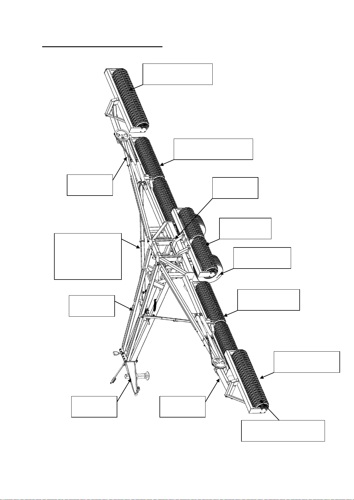
SUMMARY DRAWING / CONTENTS................................................................................................................1
EC DECLARATION OF CONFORMITY............................................................................................................2
MACHINE DESCRIPTION ...................................................................................................................................3
FIELDS OF APPLICATION.........................................................................................................................................3
DELIVERY CHECK...............................................................................................................................................3
INSTRUCTIONS REGARDING UNLOADING AND FINAL MOUNTING ............................................................................3
SAFETY INSTRUCTIONS.....................................................................................................................................5
GENERAL INFORMATION ........................................................................................................................................5
INSTRUCTIONS ON TRANSPORT ON PUBLIC ROADS..................................................................................................5
FRONT AXLE LOAD.................................................................................................................................................5
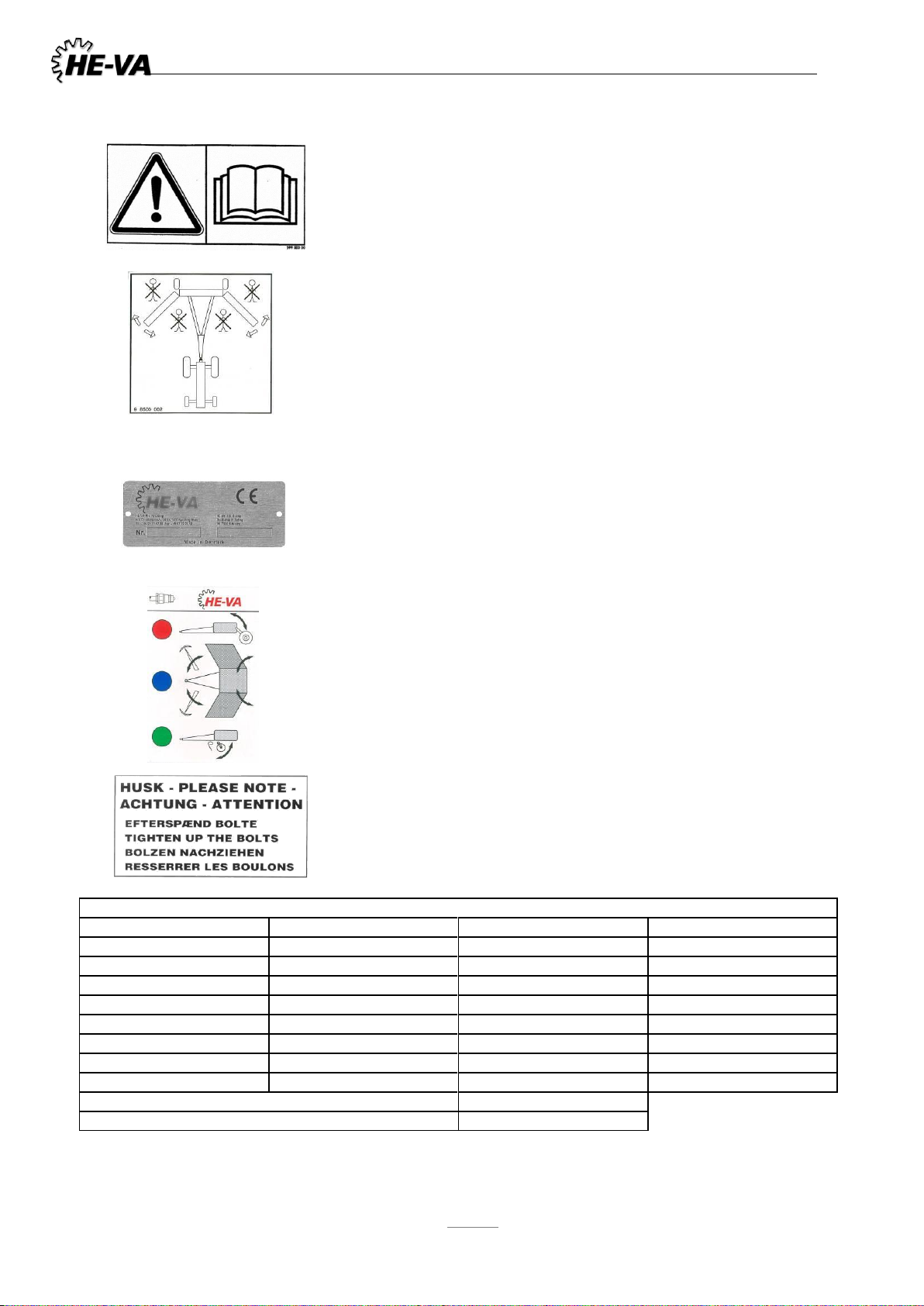
SAFETY –AND OTHER MARKINGS ON THE MACHINE...............................................................................................6
MAINTENANCE.....................................................................................................................................................7
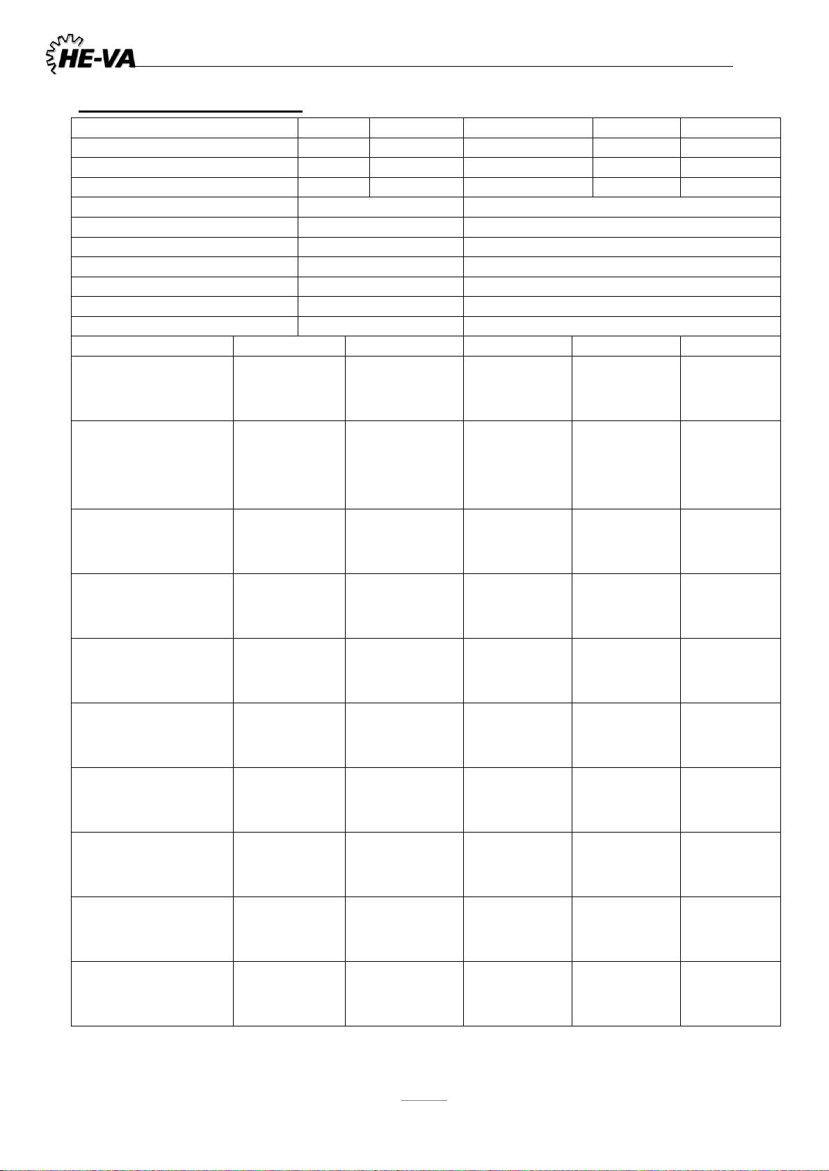
TECHNICAL SPECIFICATIONS.........................................................................................................................8
UNFOLDING...........................................................................................................................................................9
FOLDING.................................................................................................................................................................9
CONSOLIDATION .................................................................................................................................................10
SAT-SYSTEM..........................................................................................................................................................11
SPAREPARTS:........................................................................................................................................................12
BLOCK OF RINGS NO.1+5 (12,3+15,3M) ................................................................................................................12
BLOCK OF RINGS NO.1+5 (16,3+18,3+20,3M).......................................................................................................14
BLOCK OF RINGS NO.3...........................................................................................................................................17
BLOCK OF RINGS NO.2+4.......................................................................................................................................20
RING TYPES:...........................................................................................................................................................23
INNER WING:..........................................................................................................................................................24
STABILIZER BAR 15.3M..........................................................................................................................................27
STABILIZER BAR 16.3M -18,3M –20,3M................................................................................................................28
WHEEL FRAME 12,3 -15,3M...................................................................................................................................29
WHEEL FRAME 16,3 -18,3 –20,3M.......................................................................................................................30
TRIANGLE UNTIL MACHINE NO:347247.................................................................................................................31
TRIANGEL FROM MACHIN NO.347248....................................................................................................................32
DRAWBAR 12,3 -15,3M.........................................................................................................................................33
DRAWBAR 12,3 -15,3 -16,3 -18,3 -20,3M,..........................................................................................................34
DRAWBAR 12,3 -15,3 -16,3 -18,3 -20,3M,..........................................................................................................35
CHASSIS.................................................................................................................................................................36
OUTER WING..........................................................................................................................................................38
OUTER WING SECTION............................................................................................................................................39
INNER WING SECTION.............................................................................................................................................40
CENTERSECTION ....................................................................................................................................................41
HYDRAULICS.........................................................................................................................................................41
BRACKET FOR ACCUMULATOR ..............................................................................................................................41
HYDRAULIC CIRCLE:CENTRE SECTION /CHAIN CYLINDER FOR OUTER WING SECTION...........................................42
HYDRAULIC CIRCLE:SIDE SECTION /WHEEL FRAME /LOCKING CLAW .................................................................44
HYDRAULIC CIRCLE:SUPPORTING LEG ..................................................................................................................46
BRAKES...................................................................................................................................................................47
HYDRAULIC BRAKE................................................................................................................................................47
AIR BRAKE.............................................................................................................................................................48
LED -LIGHT SET....................................................................................................................................................50
LIGHTING SET:EL.DIAGRAM .................................................................................................................................51
NOTES:.....................................................................................................................................................................52

2
EC DECLARATION OF CONFORMITY
in accordance with the EU Machinery Directive 2006/42/EC
applicable as from December 29th 2009:
HE-VA ApS
N. A. Christensensvej 34,
DK-7900 Nykøbing Mors
hereby confirms that the following machine has been manufactured in accordance
with the Council Directive 2006/42/EC.
The declaration comprises the following machine:
King-Roller 12.3m –15.3m - 16,3m - 18,3m - 20,3m
Nykøbing the 01 June 201 Villy Christiansen
The undersigned is furthermore authorised to compile technical documentation for the above machine.

UK King-Roller 12.3m –15.3 - 16,3 - 18,3 –20,3m 15/05-2018
3
Machine Description
Fields of application
King-Roller is a 5-section hydraulic roller with wheels. King-Roller packs the ploughed soils, while
consolidating it to press stones into the ground. King-Roller is available in working widths of 12.3m -
15.3m - 16,3m - 18,3m and 20,3m with a choice of 10 different ring types. (20,3m = 4 choises)
The independent centre-suspended sections ensure a flexible roller which follows the contours of the
field –the centre section has the same flexible independent abilities. Thanks to the Hydraulic
Adjustable Transfer-system, which distributes the weight of the construction evenly on all 5 sections
(drawbar, cylinder and wheels), the soil pressure is uniform in the entire working width. The transfer
from working to transport position is hydraulic, and the low and compact construction permits a safe
and stable transport width of only 3.00m.
Delivery check
Check the roller for any damage. Check the hydraulic hoses for cuts and squeezing damage. Check also
that the other hydraulic components have not been damaged during transport.
Check that the frame construction has not been damaged. You should also check that the blocks of rings
have not been exposed to impacts, which may have damaged the rings or the double-sealed ball bearings.
Finally check that the transport wheel nuts are tightened and OK. Check the air pressure in the tyres
Instructions regarding unloading and final mounting
To minimize freight size, the King-Roller is delivered partly disassembled. It is therefore necessary for
the dealer to assemble the roller before delivery to the user.
Attach the roller to a tractor. As the roller tends to be heavier at the back during unfolding, causing
significant upward strain on the drawbar, the tractor must be equipped with forks or a similar type of
safety above the towing eye.
Unfold the roller to working position –however avoid raising the wheel frame.
Warning !
As the back part of the roller will be heavy when folding and
folding out the roller, the roller must be coupled in fork-
shaped drawbar or with a protection above the draw bar

UK King-Roller 12.3m –15.3 - 16,3 - 18,3 –20,3m 15/05-2018
4
Raise the roller blocks into position under the frame and mount them in the following order:
Block no. 2 and no. 4 are mounted by
Mount block no. 3, then block no. 1 and finally block no. 5.
Remember to tighten up all bolts before any operation of the machine.
Maximum torque in Nm. w/lubricated thread
Metric thread
Quality 8.8
Quality 10.9
Quality 12.9
M10x1,5
47
65
79
M12x1,75
81
114
136
M14x2,0
128
181
217
M16x2,0
197
277
333
M18x2,5
275
386
463
M20x2,5
385
541
649
M22x2,5
518
728
874
M24x3,0
665
935
1120
Wheel nut M18x1,5 fine thread
433 Nm
Wheel nut M22x1,5 fine thread
803Nm

UK King-Roller 12.3m –15.3 - 16,3 - 18,3 –20,3m 15/05-2018
5
Safety instructions
General information
Do not start-up the machine if there are persons in exposed positions* within a hazardous area**.
When persons are in exposed positions (e.g. in connection with adjustment, maintenance,
attachment and uncoupling), the following conditions must be observed:
1. The machine must be lowered to firm ground.
2. The hydraulics must be relieved.
3. The tractor must be stopped and the key removed from the ignition switch.
4. The driver must ensure that no persons are in exposed positions during the operation.
* Persons in exposed positions: Any person who is wholly or
partly within a hazardous area.
** Hazardous area: On and under the machine within a distance
of 10 m from the machine.
Most accidents that happen in connection with the operation, transport and
maintenance of machines are caused by non-compliance with the most elementary safety
conditions.
Therefore it is vital that anybody working at the machine carefully complies with the safety
instructions as well as other instructions applying to the machine.
The machine may only be operated, maintained and repaired by persons, who are familiar with
this work and who are further familiar with the possible elements of danger with this particular
machine.
Instructions on transport on public roads
Check before transport on public roads that the attachment of the machine at the tractor is in
accordance with the local rules and regulations in force (permitted total weight, permitted axle load,
transport width, lights, warning signs, etc.).
The transport wheels and construction of the King-Rollers were designed for maximum speeds of
30 km/h.
If this speed is exceeded, all warranty claims are repealed.
Front axle load
After the attachment of the machine and at maximum load, the driving properties of the tractor must
be checked. Check that the front axle is sufficiently loaded. As a minimum, the front axle load must
be 20% of the tractor weight. Permitted axle load and permitted total weight for the tractor must
always be observed.
NB! The driving, controlling and braking properties are affected by the attached machine
combination.

UK King-Roller 12.3m –15.3 - 16,3 - 18,3 –20,3m 15/05-2018
6
Safety –and other markings on the machine
Study the Operating Instructions thoroughly before any
operation of the machine and observe all safety instructions.
Take care that no persons are within the machine’s hazardous
area during the unfolding and folding procedure..
Plate with number and year of manufacture
Indication label for the machine’s hydraulic systems:
Red: Transporthjul op/ned
Blue: Hydraulics for folding the outer wing sections and
weight transfer system
Green: Support leg
Tighten up the bolts regularly. If this is not performed, our
warranty obligations will no longer apply.
Maximum torque in Nm. w/lubricated thread
Metric thread
Quality 8.8
Quality 10.9
Quality 12.9
M10x1,5
47
65
79
M12x1,75
81
114
136
M14x2,0
128
181
217
M16x2,0
197
277
333
M18x2,5
275
386
463
M20x2,5
385
541
649
M22x2,5
518
728
874
M24x3,0
665
935
1120
Wheel nut M18x1,5 fine thread
433 Nm
Wheel nut M22x1,5 fine thread
803Nm

UK King-Roller 12.3m –15.3 - 16,3 - 18,3 –20,3m 15/05-2018
7
Maintenance
A. After every approx. 10 hours of operation retighten wheels, bearings and locking rings. Hoses,
fittings and cylinders checked for leaks and tighten.
Maximum torque in Nm. w/lubricated thread
Metric thread
Quality 8.8
Quality 10.9
Quality 12.9
M10x1,5
47
65
79
M12x1,75
81
114
136
M14x2,0
128
181
217
M16x2,0
197
277
333
M18x2,5
275
386
463
M20x2,5
385
541
649
M22x2,5
518
728
874
M24x3,0
665
935
1120
Wheel nut M18x1,5 fine thread
433 Nm
Wheel nut M22x1,5 fine thread
803Nm
B. For each approximately 10 hours of operation lubricate all moving parts in the wings - and the side
sections, as well as the lubrication points on the cylinders. For about every 30 hours of operation
lubricate the cylinder studs.
Important:
After the season the roller should be cleaned. This is easily done with a high-pressure cleaner. Make
sure that all earth and dirt particles are removed. Do not use high-pressure water directly on ball
bearings, cylinders, lubricating nipples and link connections as this may cause water to penetrate these
items. After the washing all lubricating points must be lubricated and the wheel frame cylinder
greased. When the roller is dry it can be sprayed with oil.
Important:
X= Lubricating places
IMPORTANT! The ball bearings should only be lubricated with 1-2 strokes as the sealing rings could
otherwise be pressed out. Every 20 hours
The hydraulic system is filled with oil type Hydro Texaco HD32
Lubricate the piston rods with grease.
X
X
X
X
X
X
X
X
X
X
X
X
X
X
X
X
X
X
X

UK King-Roller 12.3m –15.3 - 16,3 - 18,3 –20,3m 15/05-2018
8
Technical specifications
12,3m
15,3m
16,3m
18,3m
20,3m
Working width
12,3m
15,3m
16,3m
18,3m
20,3m
Transport width
3,00m
3,00m
3,00m
3,00m
3,00m
Machine length
6,55m
7,75m
8,35m
8,35m
9,55m
Wheels
500/50x17 –18 Ply
560/45 R22.5 LI163A8
Tyre pressure at 40km/h
500/50x17 –18 Ply
4,0bar/57 p.s.i
Number of hydr. outlets
4.4bar / 63 p.s.i
3 double-acting
Hydraulic pressure (minimum):
3 double-acting
190 bar
Oil type:
190 bar
Hydro Texaco HD32
Voltage
Hydro Texaco HD32
12 volt
Working speed recommended
12 volt
7 - 10 km
Ringe
12,3m
15,3m
16,3m
18,3m
20,3m
Cambridge 510mm
No. of rings
Weight kg
Power requirement HP
236 pcs.
8560 kg
170 - 200 HP
292 pcs.
9880 kg
180 - 230HP
306 pcs.
10270 kg
190 - 240HP
346 pcs.
11680 kg
210 - 260 HP
386 pcs.
14360 kg
220 - 280 HP
Cambridge 560mm
No. of rings
Weight kg
Power requirement HP
236 pcs.
9310 kg
170 - 200 HP
292 pcs.
10820 kg
180 - 230HP
306 pcs.
11280 kg
190 - 240HP
346 pcs.
12820 kg
210 - 260 HP
Cambridge 620mm
No. of rings
Weight kg
Power requirement HP
236 pcs.
10020 kg
190 - 220 HP
292 pcs.
11770 kg
200 - 250 HP
306 pcs.
12290 kg
210 - 260 HP
346 pcs.
14240 kg
230 - 280 HP
Crosskill 485 530mm
No. of rings
Weight kg
Power requirement HP
125 pcs.
8000 kg
170 - 200 HP
153 pcs.
9250 kg
180 - 230 HP
163 pcs.
9570 kg
190 - 240 HP
183 pcs.
11020 kg
210 - 260 HP
203 pcs.
13830 kg
220 - 280 HP
Crosskill 550 600mm No.
of rings
Weight kg
Power requirement HP
125 pcs.
9400 kg
170 - 200 HP
153 pcs.
11140 kg
180 - 230 HP
163 pcs.
11610 kg
190 - 240 HP
183 pcs.
13080 kg
210 - 260 HP
2D Bølgering 500mm
No. of rings
Weight kg
Power requirement HP
150 pcs.
7480 kg
170 - 200 HP
187 pcs.
9070 kg
180 - 230 HP
199 pcs.
9330kg
190 - 240 HP
223 pcs.
10340 kg
210 - 260 HP
248 pcs.
13090 kg
220 - 280 HP
2D Corrugated 550mm
No. of rings
Weight kg
Power requirement HP
150 pcs.
8020 kg
170 - 200 HP
187 pcs.
9570 kg
180 - 230 HP
199 pcs.
9840 kg
190 - 240 HP
223 pcs.
11140 kg
220 - 270 HP
2D Corrugated 600mm
No. of rings
Weight kg
Power requirement HP
150 pcs.
8560 kg
180 - 210 HP
187 pcs.
10000 kg
190 - 240 HP
199 pcs.
10350kg
200 - 250 HP
223 pcs.
11940 kg
220 - 270 HP
Starring 450/500
No. of rings
Weight kg
Power requirement HP
244 pcs.
8200 kg
170 - 200 HP
302 pcs.
9830 kg
200 - 250 HP
316 pcs.
10350 kg
190 - 240 HP
356 pcs.
11300 kg
210 - 260 HP
396 pcs.
14160 kg
220 - 280 HP
Starring 550/600
No. of rings
Weight kg
Power requirement HP
244 pcs.
9470 kg
190 - 220 HP
302 pcs.
11400 kg
200 - 250 HP
316 pcs.
12000 kg
210 - 260 HP
356 pcs.
13160 kg
230 - 280 HP

UK King-Roller 12.3m –15.3 - 16,3 - 18,3 –20,3m 15/05-2018
9
Unfolding
1. Check that the male quick couplings mounted from the factory fit the tractor’s female quick
couplings.
2. When (un)folding, the King-Roller should be stationary on level, firm ground, while the
tractor is able to move freely.
3. Activate the hydraulics marked with red to unlock the side section transport safety, then pivot
the side sections fully backwards. The oil flow automatically switches to the wheel frame. Pull
the wheel frame forward then up.
4. With the wheels completely raised, activate the hydraulics marked with blue to fold the outer
wing sections into working position.
The Hydraulic Adjustable Transfer-system (S.A.T. System) of the King-Roller is connected to the
folding system. The S.A.T. System transfers weight from sections 2 & 4, which carry the main frame,
onto sections 1, 3 & 5. This allows you to adjust the hydraulic weight transfer system to ensure a
uniform pressure in the entire working width.
The oil pressure in the S.A.T. System can be monitored on the manometer. The hydraulics marked
with blue allows you to set the desired working pressure. 50-60 bar is recommended.
IMPORTANT:
Folding
1. When (un)folding, the King-Roller should be stationary on level, firm ground, while the
tractor is able to move freely.
2. Activate the hydraulics marked with blue to fold the outer wing sections from working position
into transport position.
3. Activate the hydraulics marked with red to lower the wheel frame down and backwards. When
the wheel are fully folded, the oil flow automatically switches to side section folding. When the
side sections are fully folded, the transport safety activates automatically.
Take care that no persons are within the machine’s hazardous
area during the unfolding and folding procedure

UK King-Roller 12.3m –15.3 - 16,3 - 18,3 –20,3m 15/05-2018
10
Consolidation
The transport wheels are to be lowered only when folding into transport position.
Never drive the roller on the wheels in working position, as it would put inappropriate strain on the
construction of the machine.
Maximum working speed 10 km/h.
When turning on the headland, turn in the widest possible curves. Only turn as sharply as to keep the
rings rotating in a forward direction.
Do not drive over large or earth-fast stones, as it may damage the rings.
When working on varying soil types, it is necessary to check the work results regularly, and possibly
adjust the Hydraulic Transfer System. Current settings can be read on the manometer in the front of the
roller.
The recommended working pressure is 50-60 bar. The best way to check the work results is for the
driver to inspect the field crosswise of the working direction. If the consolidation seems uneven, it is
necessary to adjust the hydraulic pressure:
If the consolidation is heaviest on the middle and wing outer sections, the pressure should be decreased
to reduce the weight transfer. This will put more weight on the inner wing sections (2 & 4).
If the consolidation is heaviest on the inner wing sections (2 & 4), the pressure should be increased.
This will put more weight on the centre section and outer wing sections.

UK King-Roller 12.3m –15.3 - 16,3 - 18,3 –20,3m 15/05-2018
11
SAT-System
King-Roller’s hydraulic folding system is linked to two accumulators and a pressure gauge.
The pressure gauge allows the operator to set the weight transfer level to ensure even consolidation
across the full width. The KingRoller’s main frame is supported by the two wing sections (O) cf photo.
By this SAT-System the necessary part of the roll’s weight is transferred to the centre and the outside
wing sections. () cf photo.
All five roller sections on HE-VA King-Roller are centre suspended and with independent flotation
resulting in a perfect contour following of the King-Roller
The design of HE-VA King-Roller can withstand higher working loads and HE-VA King-Rollers are
also heavier than most of the other similar rolls, ensuring a perfect consolidation.

UK King-Roller 12.3m –15.3 - 16,3 - 18,3 –20,3m 15/05-2018
12
Spareparts:
Block of rings no. 1+5 (12,3+15,3m)
1
2
3
4
5

UK King-Roller 12.3m –15.3 - 16,3 - 18,3 –20,3m 15/05-2018
13
Pos.
Item no.
Designation
12,3
m
15,3
m
1
678672720
Axle 2720mm Ø60 CrNiM06
2
1
678672520
Axle 2520 mm Ø60 (Discontinued 12,5m)
1
678672420
Axle 2420mm Ø60 CrNiM06
2
2
690140808
Bearing complete UCF 312 (Ø60)
4
4
3
690103173
Bolt M20x70 10.9
16
16
4
690113009
Self-locking nut M20
16
16
5
690117005
Facet plate Ø20
32
32
6
671040400
Stop ring w/bolt Ø60 axle
4
4
Ring types: Shown on page 23
7
690150032
Cambridge serrated ring 510 mm 21”
42
44
7
690150046
Cambridge serrated ring 620 mm 24”
42
44
8
690150042
Cambridge plain ring 510 mm (reduced hub 80mm) 21”
2
2
8
690150050
Cambridge plain ring 620 mm (reduced hub 80mm) 24”
2
2
9
690150030
Cambridge plain ring 510mm 21”
42
44
9
690150049
Cambridge plain ring 620mm 24”
42
44
10
690150007
Cam ring 22” Ended 1st.oct 2011
10A
690150063
Star ring Ø500, center Ø135, GGG50
42
44
10B
690150064
Star ring Ø450, m/hals Ø60 GGG50
42
44
10C
690150065
Star ring Ø600, center Ø135, GGG50
42
44
10D
690150066
Star ring Ø550, m/hals Ø60 GGG50
42
44
11
690150013
Corrugated ring Ø500 Ended april 2011
11A
690150042
2D- Corrugated ring Ø510 New from 1. april 2011
27
30
11B
690150050
2D- Corrugated ring Ø620 New from 1. april 2011
27
30
11C
690150104
2D - Corrugated ring Ø550
27
30
12
690150028
Plain ring Ø505
28
30
13
690150034
Crosskill ring Ø485 (Ø60)
48
52
13
690150074
Crosskill ring Ø550 (Ø60)
48
52
14
690150011
Loose Crosskill ring Ø530
43
48
14
690150075
Loose Crosskill ring Ø600
43
48
15
690150035
Hub for loose Crosskill ring
43
48
15
690150076
Hub for loose Crosskill ring Ø104/Ø60
43
48
17
630764030
Cambridge plain ring 21” hub width 82 mm
2
2
17
630764040
Cambridge plain ring 24” hub width 82 mm
2
2

UK King-Roller 12.3m –15.3 - 16,3 - 18,3 –20,3m 15/05-2018
14
Block of rings no. 1+5 (16,3+18,3+20,3m)
1
2
3
4
5

UK King-Roller 12.3m –15.3 - 16,3 - 18,3 –20,3m 15/05-2018
15
Pos.
Item
number
Designation
16,3
18,3
20,3
1
678613150
Axle 3150 mm Ø60 St.60
2
1
678614150
Axle 4150 mm Ø60 St.60
2
1
678614650
Aksel 4650 mm Ø60 St.60
2
2
690140808
Bearing complete UCF 312 (Ø60)
4
4
4
3
690103173
Bolt M20x70 10.9
16
16
16
4
690113009
Self-locking nut M20
16
16
16
5
690117005
Facet plate Ø20
32
32
32
6
671040400
Stop ring w/bolt Ø60 axle
4
4
4
Ringtypes: Shown on page 23
7
690150032
Cambridge serrated ring 510 mm 21”
54
72
80
7
690150046
Cambridge serrated ring 620 mm 24”
54
72
8
690150042
Cambridge plain ring 510 mm (reduced hub 80mm)
2
2
2
8
690150050
Cambridge plain ring 620 mm (reduced hub 80mm)
2
2
9
690150030
Cambridge plain ring 510mm 21”
54
72
80
9
690150049
Cambridge plain ring 620mm 24”
54
72
10
690150007
Cam ring 22” Ended 1st.oct 2011
10A
690150063
Star ring Ø500, Center Ø135 GGG50
58
76
86
10B
690150064
Stjernering Ø450 m/hals Ø60 GGG50
58
76
86
10C
690150065
Stjernering Ø600, Center Ø135, GGG50
58
76
10D
690150066
Stjernering Ø550 m/hals Ø60 GGG50
58
76
11
690150013
Corrugated ring Ø500 Ended from april 2011
11A
690150042
2D- Corrugated ring Ø500 New from april 2011
74
98
108
11B
690150050
2D- Corrugated ring Ø600 New from april 2011
74
98
11C
690150104
2D- Corrugated ring Ø550
74
98
12
690150028
Plain ring Ø505 Ended
13
690150034
Crosskill ring Ø485 (Ø60)
61
81
91
13
690150074
Crosskill ring Ø550 (Ø60)
61
81
14
690150011
Loose Crosskill ring Ø530
51
68
75
14
690150075
Loose Crosskill ring Ø600
51
68
15
690150035
Hub for loose Crosskill ring
51
68
75
15
690150076
Hub for loose Crosskill ring Ø104/Ø60
51
68
16
630764031
Cambridge plain ring 21” hub width 72 mm
2
2
2
16
630764041
Cambridge plain ring 24” hub width 72 mm
2
2
16
630764048
Cambridge smooth ring Ø620/Ø60, cast steel
w/red. hub (72mm) from machine no. 341981
2
2
17
630764030
Cambridge plain ring 21” hub width 82 mm
2
2
2
17
630764040
Cambridge plain ring 24” hub width 82 mm
2
2
17
630764047
Cambridge smooth ring Ø620/Ø60, cast steel
w/red. hub (72mm) from machine no. 341981
2
2
18
690117102
Shim x2mm at support bearing UC312
4
4
4
18a
690600015
Distance bush Ø60 L=15
2
2
2
19
691370150
Seeger circlip-ring outer Ø150 DIN471
2
2
2
20
630670250
Support bearing
2
2
2
21
630764008
Bearing housing f/UC 312 bearing
2
2
2

UK King-Roller 12.3m –15.3 - 16,3 - 18,3 –20,3m 15/05-2018
16
Pos.
Item
number
Designation
16,3
18,3
20,3
22
690113008
Self-locking nut M16
8
8
8
23
690117013
Facet plate Ø16
8
8
8
24
690110105
U-bolt M16x100x200x100
4
4
4
25
690140115
Bearing UC 312 (Ø60)
2
2
2
26
63067-65
Complete bearing
39
63067-57
Support bearing w/ tension : from machine no. 345884
27
630670570
Bracket for support bearing
2
2
2
28
630670617
Tension
2
2
2
29
690110105
U-bolt M16x100x200x100
4
4
4
30
690117016
Hardened washer FZB Ø17x45x6
16
16
16
31
690103004
Countersunk Allen M16x60 DIN 7991
8
8
8
32
690113008
Locking nut M16
16
16
16
33
690103213
Bolt M20x200 8.8
2
2
2
34
690117005
Facer plate Ø20
4
4
4
35
690113009
Locking nut M20
2
2
2
36
630764008
Bearing housing f/UC 312 bearing
2
2
2
37
690140115
Bearing UCF312 (Ø60)
2
2
2
38
691370150
Seeger-circlip ring outer Ø150 DIN471
2
2
2
39
63067-57
Complete support bearing w/tension
from machine no. 345884

UK King-Roller 12.3m –15.3 - 16,3 - 18,3 –20,3m 15/05-2018
17
Block of rings no. 3
1
2
3
4
5

UK King-Roller 12.3m –15.3 - 16,3 - 18,3 –20,3m 15/05-2018
18
Pos.
Item
number
Designation
12.3
15.3
16,3
18,3
20,3
1
678612960
Axle 2960 mm Ø60 St.60
1
1
1
1
1
2
690140808
Bearing complete UCF 312 (Ø60)
2
2
2
2
2
3
690103173
Bolt M20x70 10.9
8
8
8
8
8
4
690113009
Self-locking nut M20
8
8
8
8
8
5
690117005
Facet plate Ø20
16
16
16
16
16
6
671040400
Stop ring w/bolt Ø60 axle
2
2
2
2
2
Ringtypes: Shown on page 23
7
690150032
Cambridge serrated ring 510 mm 21”
26
26
26
26
26
7
690150046
Cambridge serrated ring 620 mm 24”
26
26
26
26
8
690150042
Cambridge plain ring 510 mm (reduced hub 80mm)
1
1
1
1
1
8
690150050
Cambridge plain ring 620 mm (reduced hub 80mm)
1
1
1
1
9
690150030
Cambridge plain ring 510mm 21”
23
23
23
23
23
9
690150049
Cambridge plain ring 620mm 24”
23
23
23
23
10
690150007
Cam ring 22” Ended oct 2011
10A
690150063
Star ring Ø500, Center Ø135 GGG50
26
26
26
26
26
10B
690150064
Star ring Ø450 m/hals Ø60 GGG50
26
26
26
26
26
10C
690150065
Star ring Ø600, Center Ø135, GGG50
26
26
26
26
10D
690150066
Star ring Ø550 m/hals Ø60 GGG50
26
26
26
26
11
690150013
Corrugated ring Ø500 Ended from april 2011
11A
690150042
2D- Corrugated ring Ø500 New from april 2011
35
35
35
35
35
11B
690150050
2D- Corrugated ring Ø600 New from april 2011
35
35
35
35
11C
690150104
2D- Corrugated ring Ø550
35
35
35
35
12
690150028
Plain ring Ø505 Ended
13
690150034
Crosskill ring Ø485 (Ø60)
29
29
29
29
29
13
690150074
Crosskill ring Ø550 (Ø60)
29
29
29
29
14
690150011
Loose Crosskill ring Ø530
24
24
24
24
24
14
690150075
Loose Crosskill ring Ø600
24
24
24
24
15
690150035
Hub for loose Crosskill ring
24
24
24
24
24
15
690150076
Hub for loose Crosskill ring Ø104/Ø60
24
24
24
24
24
16
630764031
Cambridge plain ring 21” hub width 72 mm
1
1
1
1
1
16
630764041
Cambridge plain ring 24” hub width 72 mm
1
1
1
1
16
630764048
Cambridge smooth ring Ø620/Ø60, cast steel
w/red. hub (72mm) from machine no. 341981
1
1
1
1
17
630764030
Cambridge plain ring 21” hub width 82 mm
1
1
1
1
1
17
630764040
Cambridge plain ring 24” hub width 82 mm
1
1
1
1
17
630764047
Cambridge smooth ring Ø620/Ø60, cast steel
w/red. hub (72mm) from machine no. 341981
1
1
1
1
18
690117102
Shim x2mm at support bearing UC312
2
2
2
2
2
18a
690600015
Distance bush Ø60 L=15
1
1
1
1
1
19
691370150
Seeger circlip-ring outer Ø150 DIN471
1
1
1
1
1
20
630670250
Support bearing
1
1
1
1
1
21
630764008
Bearing housing f/UC 312 bearing
1
1
1
1
1
22
690113008
Self-locking nut M16
4
4
4
4
4
23
690117013
Facet plate Ø16
4
4
4
4
4
Table of contents
Other HE-VA Tractor Accessories manuals