HealthWay SuperV Series User manual
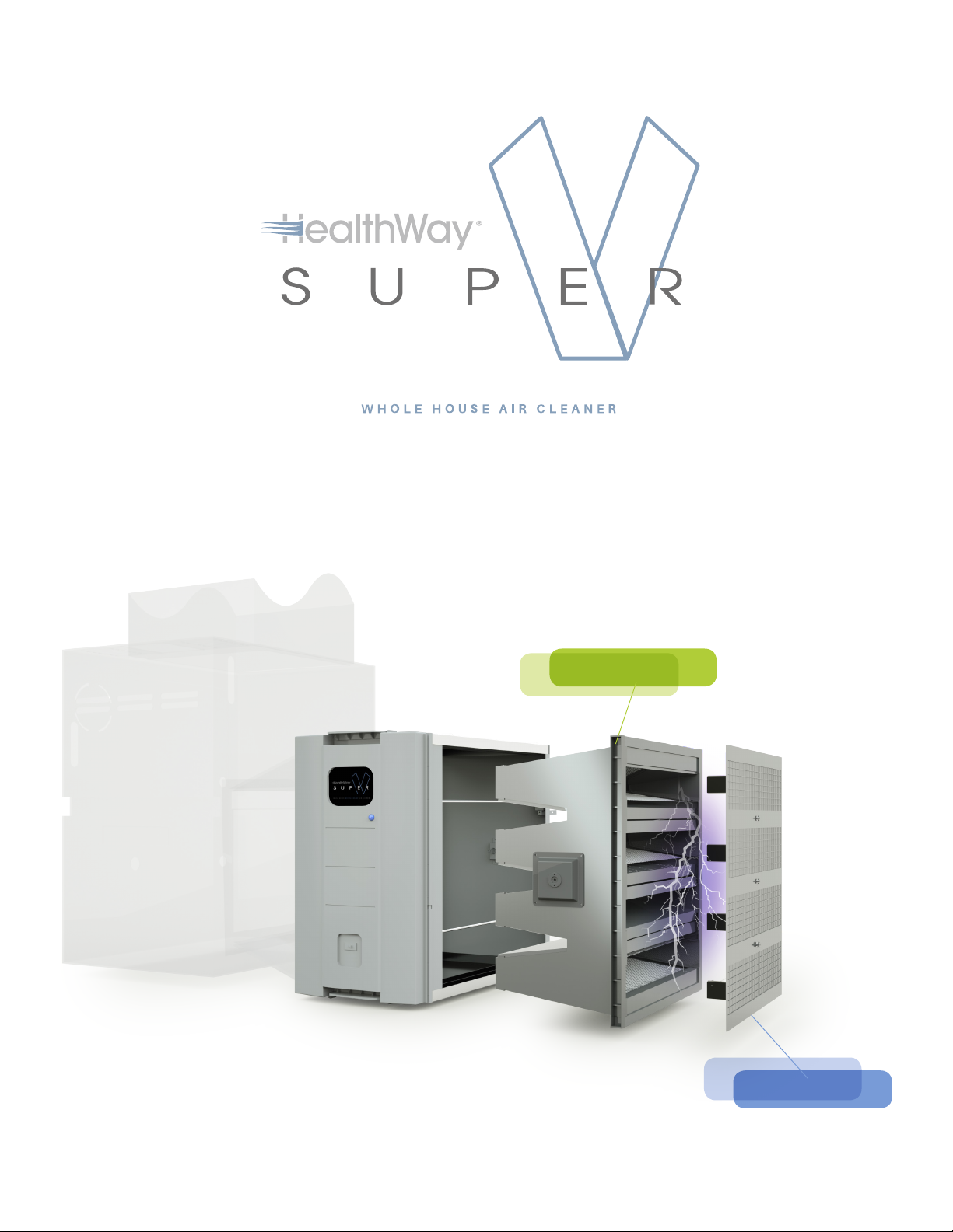
SUPER V-BANK FILTER
HIGH-ENERGY GRID
The Super V Whole-House Air Cleaner
with Patented DFS Technology
Model3400/5100
DFS Filtration System


3
Healthway © 06/2019 All rights reserved.
Table of Contents
Exploded View and Major Features.......................... 4
Features................................................................................ 4
SuperV 3400 Exploded View................................... 4
SuperV 5100 Exploded View.................................... 5
Rear View of Filter Access Door .............................. 5
System Overview ................................................................ 6
Safety Precautions.......................................................... 6
Perfomance Data............................................................. 6
Unit Description................................................................ 7
Component Description.............................................. 7
Receiving and Unpacking.............................................. 8
Receiving............................................................................. 8
Storage.................................................................................. 8
Unpacking and Inspection......................................... 8
Installation Procedures..................................................... 8
Location Determination............................................... 8
Power Requirement ....................................................... 9
Super V System Applications.................................... 9
SuperV 3400 Furnace Installation........................10
SuperV 5100 Furnace Installation ........................11
System Operation .............................................................12
To Connect Unit to Power.........................................12
To Turn on the Unit .......................................................12
To Turn off the Unit .......................................................12
Maintenance........................................................................12
SuperV 3400 Filter Replacement .........................12
SuperV 5100 Filter Replacement..........................13
Cleaning the Unit...........................................................14
Parts List.............................................................................15
Testing Steps ...................................................................15
DFS Troubleshooting Guide....................................16
Limited Warranty ...............................................................18
Appendix A - Installation Schematics.....................19
Appendix A1 - 120V with EAC ................................... 20
Appendix A2 - 120V without EAC ............................21
Appendix A3 - 208-480V with EAC........................ 22
Appendix A4 - 208-480V with EAC.........................23
Part Number: #10077
Address: HealthWay, Inc.
3420 Maple Ave.
Pulaski, NY 13142
Phone No: 315-298-2904
1-800-843-3860
Fax No: 315-298-6992
Email: [email protected]

4
Healthway © 06/2019 All rights reserved.
FEATURES
• High Air Flow Capacity – delivers high CFM with low
energy consumption
• Whole House Design – designed to deliver clean air
for the whole house
• Up to 99% Efficient on All Ultrafine Particles – down to a
size of 0.007 microns
• Versatile & Symmetrical Design –can be installed on
either supply or return side of the furnace
• Patented V-Bank Filter –increases surface area and
provides higher dust loading capacity
• Up to three times longer filter span – compared to
conventional HEPA Filtration – Lower Maintenance Cost
• Ease of Maintenance – quick access to filter in a few steps
• Smart Air Flow Monitor - Auto-flow detection to turn on
DFS power
• Designed to Last - durable powder coated galvanized
steel housing
• Hassle-free Installation - pre-drilled standing flanges to
accommodate attachments to other system components
and quick plug in for power to the system
• 100% Sealed System - high memory sponge neoprene
door gaskets to ensure door to filter seal and gaskets on
main filter eliminate air bypass
Major Features and Exploded Views
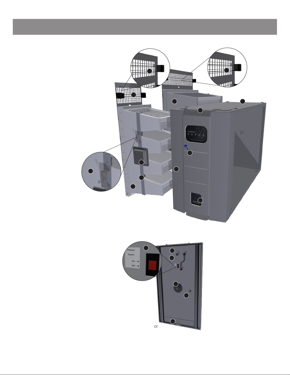
SUPERV 3400 EXPLODED VIEW
1 High Energy Grid
2 High Energy Wire
3 Main Filter
4 Filter Access Door
5 Snap Latch
6 Main Housing
7 DFS Light
8 Power Switch
9 High Energy Contact Pad
3
9
1
7
6
4
5
8
Exploded View 1:
3400 Whole Unit
2
5
Healthway © 06/2019 All rights reserved.
SUPERV 3400 & 5100 REAR VIEW OF FILTER ACCESS DOOR
13 High Energy Contact Spring
14 Air Flow Monitor*
15 Fuse & Fuse Holder**
16 Mounting Screw
17 Slide Switch ***
Major Features and Exploded Views
SUPERV 5100 EXPLODED VIEW
1 High Energy Grid
2 High Energy Wire
3 Main Filter
4 Filter Access Door
5 Snap Latch
6 Main Housing
7 DFS Light
8 Power Switch
9 High Energy Contact Pad
10 Extension filter (Smaller filter)
11 Extension filter (Smaller filter)
ground Bracket
12 Extension filter (Smaller filter)
contact bracket with spring
3
9
11
10
1
7
6
4
5
8
Exploded View 2:
5100 Whole Unit
Exploded View 3:
Rear View of Filter Access Door
* DFS turns on automatically as the air handler provides air flow.
Refer to Page 8, Installation Procedures, Before the Installation, #4 & #5, for detailed instructions.
** Fuse and fuse holder locates inside the filter access door compartment and is only accessible by unscrewing part 16 - mounting screw,
to open up the metal board.
*** Refer to Appendix A for slide switch setting.
2
2
12
15
16
14
13
16
17
6
Healthway © 06/2019 All rights reserved.
SAFETY PRECAUTIONS
Personnel who will operate this system or those who will perform maintenance thereon, must be given all manuals and
other instructions regarding safe operation of the filtration system.
This manual contains general recommendations, but specific requirements may apply to individual installations.
Such requirements are outlined in federal, state, and local codes. Compliance with applicable codes and strict
adherence to these installation instructions are the sole responsibility of the user.
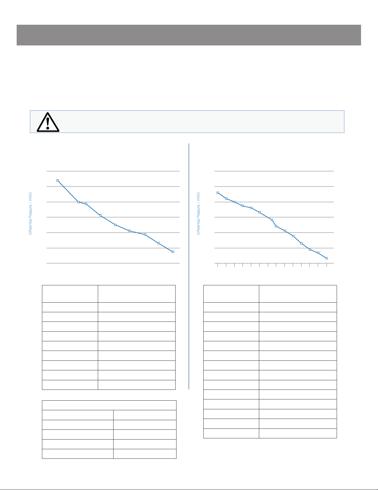
SUPERV 3400 PERFORMANCE DATA SUPERV 5100 PERFORMANCE DATA
This symbol will be used throughout this manual to indicate safety checkpoints. Failure to heed
these warnings and notices may result in damage to the unit and/or injury or death to personnel.
System Overview
Performance data subject to change without notice.
0.00
0.05
0.10
0.15
0.20
0.25
0.30
2000 1800 1600 1400
Air Flow / CFM
Air Flow & Pressure
1200 1000 800 600 400
0.00
0.05
0.10
0.15
0.20
0.25
0.30
3000
Air Flow / CFM
Air Flow & Pressure
2800 2600 2400 2200 2000 16001800 1400 1200 1000 800 600 400
Air Flow Rate
(CFM)
Differential Pressure
(inWG)
2000 0.27
1700 0.20
1600 0.19
1400 0.16
1200 0.13
1000 0.11
800 0.09
600 0.07
400 0.04
Air Flow Rate
(CFM)
Differential Pressure
(inWG)
3000 0.230
2800 0.215
2600 0.200
2400 0.185
2200 0.180
2000 0.165
1700 0.145
1600 0.120
1400 0.105
1200 0.085
1000 0.065
800 0.045
600 0.030
400 0.020
Efficiency (3400 & 5100)
Removing PM 5.0 Up to 100%
Removing PM 2.5 Up to 99.99%
Removing PM 0.5 Up to 99.87%
Removing PM 0.3 Up to 99.61%
Removing PM 0.007 Up to 99%

7
Healthway © 06/2019 All rights reserved.
COMPONENT DESCRIPTION
The Super V System integrates components symmetrically to work with any furnace set-ups. All electronic components
are located inside the filter access door. Change of filter is a breeze. It works in conjunction with the furnace to optimize
the performance.
*Replacement period depends on the level of pollution in the environment
** Replace Main Filter more often if pollution level is high
***Clean the High Energy Grid once a year or as needed
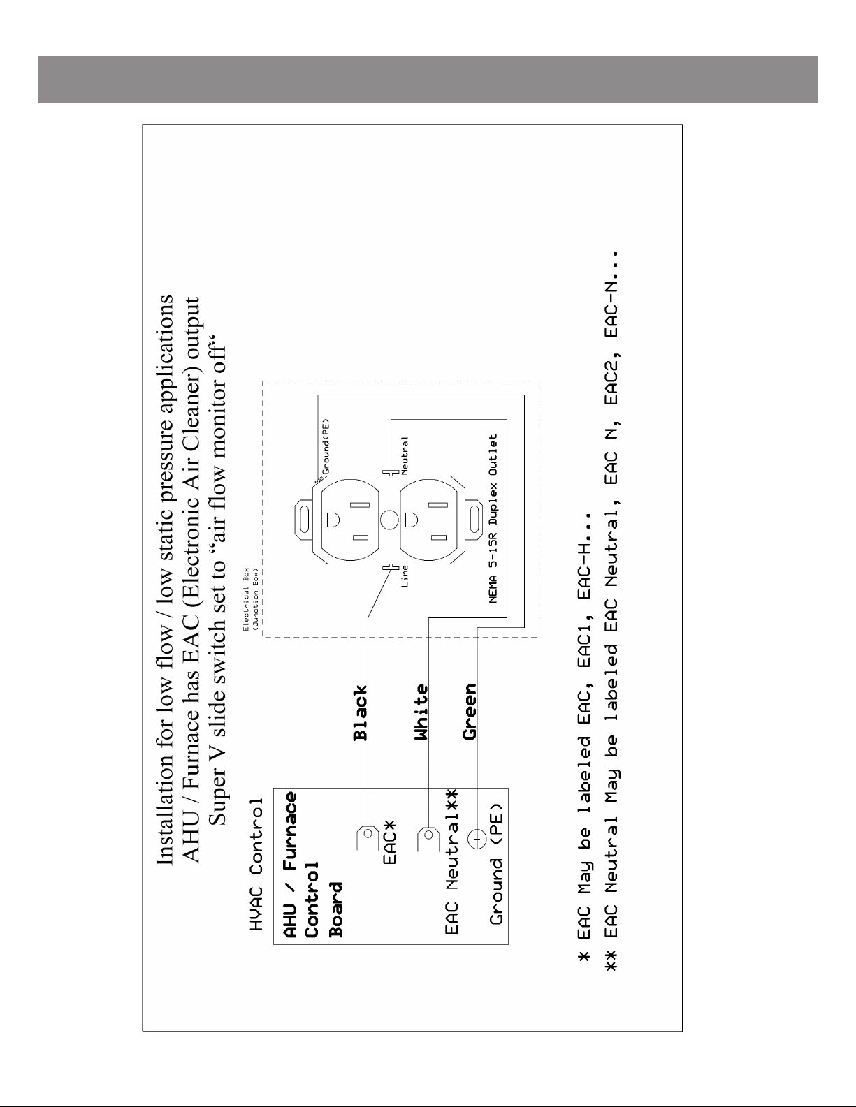
Note: The Super V system can be installed to a 208V-480V AHU/Furnace.
Refer to Appendix A - “208V-480V input with EAC” for details.
UNIT DESCRIPTION
The Super V 3400/5100 Whole House DFS Air Cleaning System is a high performance system that utilizes patent-
ed award winning Disinfecting Filtration System technology. DFS technology electrically enhances a low efficien-
cy, high flow, low pressure drop (0.27” @ 2000cfm /0.23” @ 3000cfm) filter to high efficiency while retaining the
low pressure drop and longer life advantages of the base filter material. This technology has also been shown to
inhibit bacteria growth on the filter by microbiostasis.
The Electrical Components are located inside the filter access door.
The Super V System is available in the following model:
The electrical power requirements for each individual unit are on the serial number label on
the back side of the filter access door. These requirements supersede all other
inferences to power requirements.
Components Efficiency Replacement/
Maintenance frequency*
DFS V-Bank Main Filter** DFS V-Bank Main Filter**
Up to 99% Efficient (down to .007 microns) Every 3 years at 50% duty cycle
High Energy Grid ***
Components Description
Filter Access Door Where the control panel , air flow monitor and electrical components located
Height Width Depth Weight Shipping Weight
SuperV 3400 24in 670mm 14in 356mm 27in 686mm 48lbs 22kg 58lbs 27kg
SuperV 5100 24in 670mm 14in 356mm 39in 990mm 65lbs 30kg 77lbs 35kg
System Overview
Model Power Requirement FLA Power Usage
V Hz Phase AMPS WATTS
SuperV 3400/5100 110 50 / 60 1 0.08A - 110V 7W - 110V

8
Healthway © 06/2019 All rights reserved.
Receiving and Unpacking
RECEIVING
Equipment is prepared for shipment in accordance with the Uniform Freight Classification. It is thoroughly inspected at
the factory and barring damage in transit, should be received in good condition.
When a freight carrier signs the HealthWay bill of lading, the carrier accepts the responsibility for any subsequent
shortages or damage evident or concealed. Inspection by the carrier of damage evident or concealed must be requested.
Evident shortage or damage should be noted on the carrier’s delivery document before signature of acceptance. Claims
must be made against the carrier by the purchaser.
Filtration systems are shipped as fully assembled filter units with field installation necessary. These filter units must be
handled and moved using proper rigging techniques, avoiding concentrated stresses that will distort the parts.
STORAGE
If the unit is not to be installed promptly, store it in a dry place protected against moisture, dust, physical damage,
weather, corrosion and excessive heat.
UNPACKING AND INSPECTION
The unboxing procedure may require more than one person to handle.
Unit is packaged in a heavy duty carton with foam pieces inside for protection. Place unit on a flat, clean and dry surface.
Carefully unbox the carton, remove the foam pieces on top and slowly pull out the unit covered with a plastic protection bag.
Remove the plastic bag.
Inspect physical damage on the unit surface as well as the power cord. Contact Healthway’s Customer Service Department if damage
is found.
LOCATION DETERMINATION
The filtration system location should be carefully planned with consideration given to ease of access for filter
replacement or repair of electronics located inside the filter access door.
Enough room (min 25 inches or 635 mm) must be available next to the filter access door for maintenance and filter replacement.
The inlet duct also must have at least 8” of straight duct before any bends are made.
There should be no use or spillage of powdered products, aerosols, sprays, or mists near the inlet connection to the filter.
Do not install the filtration system in an exterior environment, unless it is specifically made for exterior installations.
Standard units are for indoor use only.
Installation Procedures
Before the Installation:
1. For your safety, please read the rules and instructions in this user manual carefully.Failure
to follow them could result in serious damage in the air cleaner or cause hazardous condition.
2. Check the information shown on the nameplate to make sure rating is appropriate to
your local application.
3. Clean the furnace blower and ductwork because the Super V System cannot remove
existing mud, dust etc. from the furnace blower and ductwork.
4. Check air flow direction. When the Super V System is installed on return side of the
furnace, the auto flow monitor should be connected to the return barbed connector at
the up-right corner-factory default setting. (Fig.A - Return Connection)
5. When the Super V System is installed on supply side of the furnace, the auto flow monitor
should be connected to the supply barbed connector at the up-left corner
(Fig.B - Supply Connection) (Fig. B - Supply Connection)
(Fig. A - Return Connection)
9
Healthway © 06/2019 All rights reserved.
Furnace
Inlet DuctSupply Duct
Installation Procedures
Fig. 1-5 |Horizontal Furnace, Vertical Cleaner
Supply Duct
Furnace
Inlet Duct
Supply Duct
Inlet Duct
Furnace
Furnace
Supply Duct
Inlet Duct
Furnace
Inlet Duct
Supply Duct
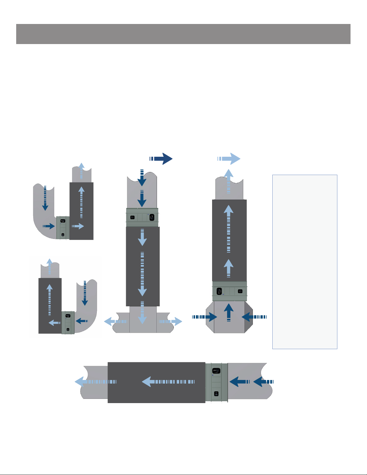
Fig. 1-1 |Up Flow Furnace
Vertical Cleaner
Fig. 1-3 |Down Flow Furnace
Horizontal Cleaner
Fig. 1-2 |Up Flow Furnace
Vertical Cleaner
(reverse)
Fig. 1-4 |Up Flow Furnace
Horizontal Cleaner
Return air flow Supply air flow
SUPER V SYSTEM APPLICATIONS
Select a mounting position according to the application. Place the unit between the main inlet duct and furnace, in a
location which is accessible for checking and replacing the filter. The unit is capable to be installed either left side or
right side of the furnace credit to its symmetrical feature and flippable housing-filter complex.
The Super V System
can also be installed
on the supply side
of the air handler,
making sure the
air flow direction
through the air
cleaner is correct. In
this case, the auto
flow monitor must
be connected to the
supply barbed
connector as
described on #5
under “Before the
Installation”
on Page 8 (refer
to Fig. B - Supply
Connection).
POWER REQUIREMENT
Refer to information on Page 7, Unit Description for details.
*Electrical disconnects may also be required - check local electrical codes

10
Healthway © 06/2019 All rights reserved.
Inlet Air Flow
Outlet Air Flow
Fig. 2-1 Fig. 2-2
Installation Procedures
SUPERV 3400 FURNACE INSTALLATION
Determine the correct air flow direction. The inlet air
is marked with an air flow label, the filter header and
high-energy grid should be placed on the inlet side
(Fig. 2-1 & 2-2)
a. If the furnace has a left-side opening, place the air
cleaner unit (default filter direction) on the left side of
the furnace
b. If the furnace has a right-side opening, pull off the
filter access door, flip the unit up-side down, put the
door back, and then place the unit on the right side of
the furnace
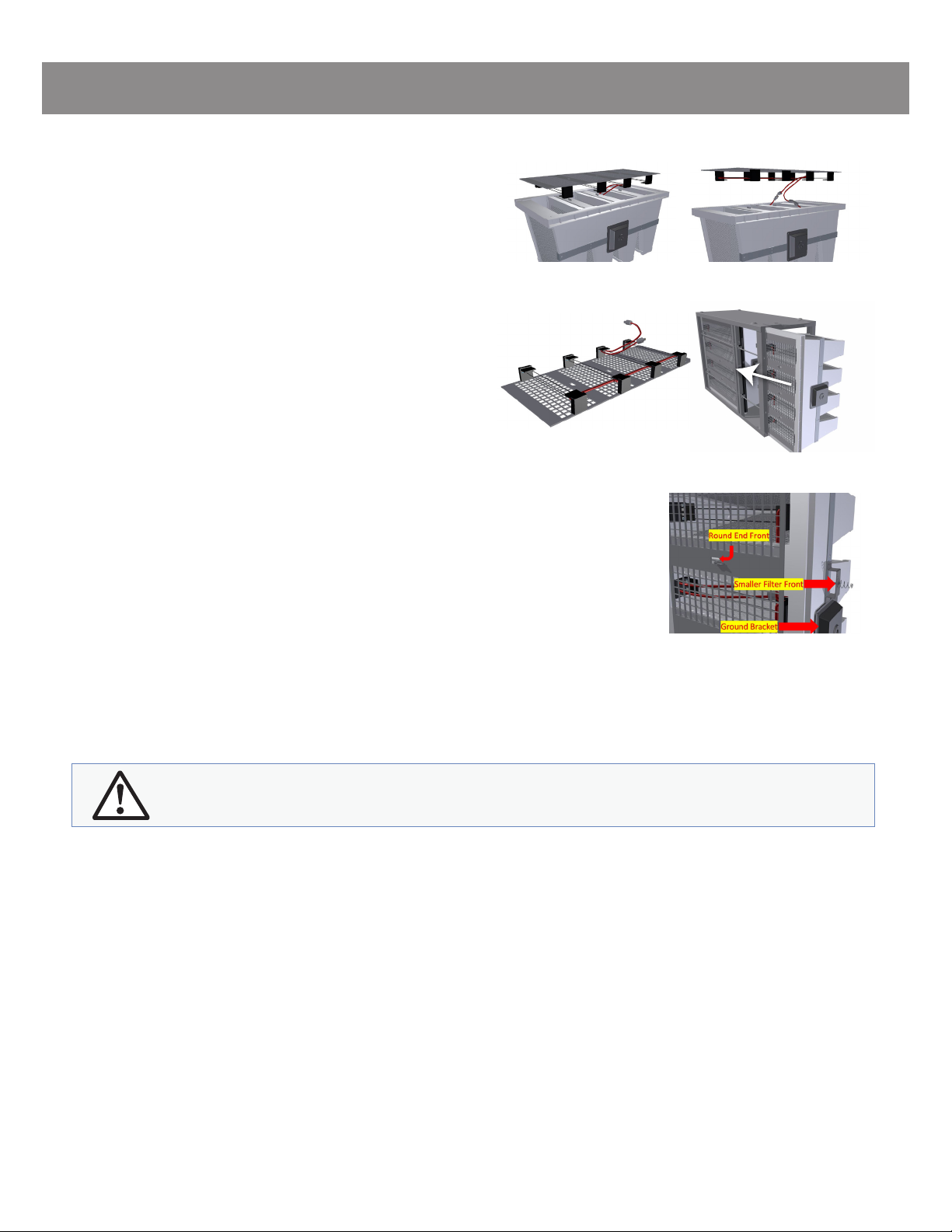
Pull up the snap latch, pull out the filter access door,
turn the quarter-turn counter-clockwise to unlock the
filter and slide the main filter out (Fig. 2-3 & 2-4)
Locate the mounting holes from the unit and connect
the unit to the furnace opening (Fig. 2-5). If the furnace
and air cleaner openings are different, use a transition
plenum (Fig. 2-6).
The opening on the Super V System is 21” ×22”.
Mount return ductwork to the air cleaner system (Fig. 2-7)
Slide the main filter into the housing from the front (Fig. 2-8)
Turn the quarter-turn clockwise to lock the filter (Fig. 2-4)
Seat the Filter access door on the bottom snap latch, pull
up the top snap latch and push close the door towards
the housing. (Fig. 2-8)
All electrical connections must be done by a certified
electrician, following the directions listed in this manual.
Check the serial number label for all the electrical requirements for this unit.
Before installation of unit, please remove all dirty filters on return side of the AHU/Furnace.
Do not connect power to the unit until the High Energy Grid wires have been
checked for proper connection.
Fig. 2-5
Fig. 2-7
Fig. 2-6
Fig. 2-8
Fig. 2-3 Fig. 2-4

11
Healthway © 06/2019 All rights reserved.
Inlet Air Flow
Outlet Air Flow
Fig. 2-9 Fig. 2-10
Installation Procedures
SUPERV 5100 FURNACE INSTALLATION
Determine the correct air flow direction. The inlet air
is marked with an air flow label, the filter header and
high-energy grid should be placed on the inlet side
(Fig. 2-9 & 2-10)
a. If the furnace has a left-side opening, place the
air cleaner unit (default filter direction) on the left side
of the furnace
b. If the furnace has a right-side opening, pull off the
filter access door, flip the unit up-side down, put the
door back, and then place the unit on the right side of
the furnace
Hold up the snap latch, pull out the filter access door,
turn the quarter-turn counter-clockwise to unlock the
filter and slide out both filters
(the smaller filter comes out first) (Fig. 2-11 & 2-12)
Locate the mounting holes from the unit and connect
the unit to the furnace opening (Fig. 2-13)
If the furnace and air cleaner openings are different,
use a transition plenum (Fig. 2-14)
The opening on the Super V System is 32” ×22”.
Mount return ductwork to the unit (Fig. 2-15)
Slide both filters (Slide in the larger filter first)
into the housing from the front (Fig. 2-12)
Turn the quarter-turn clockwise to lock
the filter (Fig. 2-12)
Seat the Filter access door on the bottom snap latch,
hold up the top snap latch and push close the door
towards the housing. (Fig. 2-16)
Fig. 2-13
Fig. 2-15
Fig. 2-14
Fig. 2-16
Fig. 2-11 Fig. 2-12

12
Healthway © 06/2019 All rights reserved.
System Operation
TO CONNECT UNIT TO POWER
Thoroughly inspect the power cord comes with the unit. Contact
HW customer service if it is damaged. If the power cord is in good
working condition, plug it in an appropriate power outlet. The unit
should be ready for operation once connected to power and furnace
blower is on.
TO TURN ON THE UNIT
Turn on the power switch located on the bottom of the filter access
door. When the blower of the furnace is on and the indicating light is
illuminated blue, DFS is functioning properly.
TO TURN OFF THE UNIT
To turn off the DFS of the unit, simply turn off the power switch
located on the bottom of the filter access door.
Maintenance
When replacing filters use only HealthWay certified filters. HealthWay filters are designed for
high voltage operation. Use of non-HealthWay filters can be hazardous to personnel and
equipment voiding the warranty.
Always unplug the unit and turn off the electrical switches and circuit breakers/disconnects before
maintenance on the unit. Wait a minimum of 30 seconds before touching the unit.
When replace filter(s), please wear safety gloves or use other hand protections.
SUPERV 3400 FILTER REPLACEMENT
Pull the latch up and pull the filter access door off (Fig. 3-1 & 3-2)
Turn the quarter-turn counter-clockwise to unlock the
filter (Fig. 3-3)
Slide out the filter (Fig. 3-4)
Place filter on a flat and dry surface with the filter header
side up (Fig. 3-5)
Unlock all three trim lockers and lift the high energy grid up
(Fig. 3-6 and Fig. 3-7)
The high energy grid is connected to the main filter through
a red wire with a connector. Unscrew the connector to
disconnect the wiring (Fig. 3-8)
Fig. 3-1
Fig. 3-3
Fig. 3-2
Fig. 3-4

13
Healthway © 06/2019 All rights reserved.
Maintenance
Place high energy grid on a flat, clean and dry surface with
high energy wires facing up (Fig. 3-9)
Connect the contact red wire from the high energy grid to
the new filter by securely screwing in the connector (Fig. 3-8)
Carefully place high energy grid on filter. Make sure each wire
sits in between filter media (Fig. 3-7)
Lock the high energy grid with all 3 trim lockers (Fig. 3-6)
Slide filter into housing until filter reaches spring at
the back. (Fig. 3-10)
Turn the quarter-turn clockwise to lock the filter (Fig. 3-3)
Pull the latch up and push securely reinstall the filter access door
Fig. 3-5
Fig. 3-15
Fig. 3-7
Fig. 3-6
Fig. 3-16
Fig. 3-8
Fig. 3-9 Fig. 3-10
SUPERV 5100 FILTER REPLACEMENT
Hold the latch up and pull out the filter access door off
(Fig. 3-11 & 3-12)
Turn the quarter-turn counter-clockwise to unlock the filter
(Fig. 3-13)
Slide out the smaller filter (Fig. 3-14)
Slide out the larger filter (Fig. 3-15)
Place both filters on a flat and dry surface with the filter header
side up (Fig. 3-16, only shows the smaller filter)
Unlock all three trim lockers and lift the high energy grid up
(Fig. 3-17 and Fig. 3-18)
The smaller filter has 2 sets of high voltage wires
(2 female connectors and 2 male connectors). Unscrew both
of the connectors to disconnect the wirings (Fig. 3-18)
Place high energy grid on a flat, clean and dry surface with high
energy wires facing up (Fig. 3-19)
Connect both the contact red wires from the high energy grid to
the new filter by securely screwing in the connector (Fig. 3-18)
Fig. 3-11
Fig. 3-13
Fig. 3-12
Fig. 3-14
14
Healthway © 06/2019 All rights reserved.
Do not use alcohol or cleaners that may damage acrylics, plastics or aluminum.
Fig. 3-17 Fig. 3-18
CLEANING THE UNIT
Depending on contamination level, this procedure should be conducted about once a year or during each filter
change or if an electrical problem occurs.
Remove the V-Bank Main Filter and High Energy Grid Assembly
Refer to page 10 and 11 for proper instructions.
To clean the High Energy Wires, use a lint-free cloth, either dry or moistened with distilled or deionized water, clean along
the length of each wire, extension spring, and acrylic standoff.
Clean the inner surfaces of the High Energy Grid material using a lint-free cloth moistened with distilled or
deionized water.
Clean the High Energy Grid surface by vacuuming between the wires using a small vacuum attachment or by using a lint
free cloth, either dry or moistened with distilled or deionized water. Take care to avoid leaving large fibers snagged on the
wires, control grid, or other components of the High Energy Grid.
Make sure that any contaminant that falls to the bottom of the filter unit is removed.
In extreme cases, it may be necessary to remove the wires from the springs attached at each end to the power distribution
bars, thus allowing complete access to the inside of the High Energy Grid assembly for cleaning as previously described.
It is recommended that the manufacturer be contacted for detailed instructions should this step appear necessary.
Reinstall the High Energy Grid, V-Bank Main Filter and filter access door as previously instructed.
Fig. 3-19 Fig. 3-20
Fig. 3-21
Carefully place high energy grid back on filter. Make sure each
wire sits in between filter media (Fig. 3-17). Please be advised that
the round end on the high energy grid faces filter front. (Fig. 3-21)
Lock the high energy grid with all 3 trim lockers (Fig. 3-16)
Please refer to user manual Fig. 3-1 to Fig. 3-10 for larger filter
replacement instructions.
Slide both filters (larger filter first) into housing until larger filter
reaches spring at the back and the smaller filter’s back spring
push against the larger filter (Fig. 3-20)
Turn the quarter-turn clockwise
to lock the filter (Fig. 3-13)
Pull the latch up and push securely
reinstall the filter access door (Fig. 3-11)
15
Healthway © 06/2019 All rights reserved.
Maintenance
Super V 3400
Part Description Part Number
Main Filter Super V main filter assembly SSV3400_MainFilter
Frame Super V 3400 metal frame assembly SSV3400_Frame
Filter Access Door Filter access door SSV3400_Door
Main Filter Grid Main filter high energy grid SSV3400_HEGrid
Super V 5100
Part Description Part Number
Main Filter Super V main filter assembly SSV3400_MainFilter
Frame Super V 5100 metal frame assembly SSV3400_FrameEXT
Filter Access Door Filter access door SSV3400_Door
Main Filter Grid Main filter high energy grid SSV3400_HEGrid
Smaller Filter Super V 5100 smaller filter assembly SSV3400_MainFilterEX
Smaller Filter Grid Super V 5100 smaller filter
high energy grid SSV3400_HEGridEXT
PARTS LIST
HealthWay recommends that the following spare parts be available on-site at all times.
Order all parts by contacting:
Phone No: 315-298-2904
1-800-843-3860
Fax No: 315-298-6992
Email: [email protected]
For additional troubleshooting assistance refer to the DFS Troubleshooting Guide or contact HealthWay;
Monday-Friday, 8am-5pm EST:
Phone No: 315-298-2904
1-800-843-3860
Fax No: 315-298-6992
Email: [email protected]
TESTING STEPS
Testing Step 1
Make sure the Super V System is plugged in and the power switch on the filter access door is in the “On” position.
Testing Step 2
The Super V System only functions when the furnace blower is providing air flow. Adjust thermostat so the furnace
receives a run command or place thermostat in ventilation mode (if equipped).
Testing Step 3
The Blue LED on the filter access door should be lit indicating proper function of the DFS system.

16
Healthway © 06/2019 All rights reserved.
Maintenance
DFS TROUBLESHOOTING GUIDE
Refer to page 4 & 5 to view the exploded view for location of the components.
Symptom #1: Blue LED turns on initially but then turns off.
Probable Cause #1: Excessive amount of debris or possible metal or conductive debris in main filter area, High Energy Grid
and High Energy Wires.
Solution:
Step 1: Disconnect the electrical power to the furnace.
Step 2: Unplug the Super V System.
Step 3: Remove the filter access door by lifting up on the top door latch and gently pulling the top of the door
towards you.
Step 4: Locate the filter locks and using a Flat Head screwdriver to turn the filter locks ¼ turn
Counter-Clockwise to unlatch the filter.
Step 5: Remove the main filter from the main housing and gently lay the filter down with the high energy grid
facing up.
Step 6: Looking through the high energy grid and observe if there is any large debris lodged in the filter and high
energy grid area. If this is the case, proceed to the high energy grid removal instructions and gently,
carefully remove any debris from the high energy grid area.
Step 7: Reinstall the high energy grid. Main Filter and the Filter Access Door. Turn the filter locks clockwise turn to lock
the filter. Plug in the Super V System and return electrical power to the furnace. Repeat testing steps 1 – 3.
If the Blue LED stays lit, the problem has been solved.
Probable Cause #2: Filter Access Door is not completely shut.
Solution:
Step 1: Turn off the electrical power to the furnace.
Step 2: Unplug the Super V System.
Step 3: Remove the Filter Access Door by lifting up on the top door latch and gently pulling the top of the door
towards you, after pulling the top of the door far enough to clear the top door latch, gently pull door up, fully
releasing the door from the unit.
Step 4: Re-attach the Filter Access Door to the Super V System. The bottom of the door has an alignment bracket to
ensure the door is centered. Start by sliding the alignment bracket into the slot at the bottom of the unit then
firmly push the top of the door in until the top door latch snaps into place. Repeat testing steps 1 – 3.
If the Blue LED lights and stays lit, the problem has been solved.
Symptom #2: Blue LED Never turns on.
Probable Cause #1: Filter Access Door not completely shut.
Solution:
Same as Symptom #1, Probable Cause #2.

17
Healthway © 06/2019 All rights reserved.
Probable Cause #2: Blown Fuse.
Solution:
Step 1: Turn off the electrical power to the furnace.
Step 2: Unplug the Super V System.
Step 3: Remove the Filter Access Door by lifting up on the top door latch and gently pulling the top of the door
towards you, after pulling the top of the door far enough to clear the top door latch, gently pull door up, fully
releasing the door from the unit.
Step 4: Locate the fuse holder on the inside of the Filter Access Door. See page 5 component 12.
Step 5: Remove the fuse using a Phillips head or Flat tipped screwdriver.
Step 6: Replace fuse with 250V 2A and tighten fuse holder cap with Flat or Phillips head screwdriver. Reinstall the
Filter Access Door, Plug in the Super V and return power to the furnace. Repeat testing steps 1 – 3.
If the Blue LED stays lit the problem has been solved.
Probable Cause #3: Air flow monitor is not activated.
Solution:
Step 1: Turn off electrical power to furnace.
Step 2: Unplug the Super V System.
Step 3: Remove the Filter Access Door by lifting up on the top door latch and gently pulling the top of door towards
you, after pulling the top of door far enough to clear the top door latch, gently pull door up, fully release the
door from the unit.
Step 4: Locate the slide switch on the back of Filter Access Door (See page 5 component 14).
Step 5: Slide the Switch with a screw driver or appropriate tool to turn the switch to “OFF” position.
Step 6: Use Appedix A-1 or A-2 to finish installation.
Step 7: Reinstall Filter Access Door, Plug in Super V and return power to the furnace. Repeat testing steps 1 – 3.
If these steps do not resolve any issues with the Healthway Super V System, please contact an HVAC professional for
further troubleshooting and repair as any further action requires repair or replacement of non-user serviceable parts.
Maintenance

18
Healthway © 06/2019 All rights reserved.
LIMITED WARRANTY
Your Healthway Super V Air Cleaner is expressly warranted for five (5) years from the date of installation to be
free from defects in materials or workmanship, except, however, for the disposable media and control grid
including high energy wires which will have to be replaced from time to time depending upon the use. Health-
way’s exclusive obligation under this warranty shall be to supply, without charge, a replacement for any part of
the Super V Air Cleaner which is found to be defective within such five (5) year period and which is returned not
later than thirty (30) days after said five (5) year period by you or your original supplier to Healthway, Pulaski, NY
13142, together with the model number and installation date of the Super V.
THIS WARRANTY SHALL NOT OBLIGATE HEALTHWAY FOR ANY LABOR COSTS AND SHALL NOT APPLY
TO DEFECTS IN WORKMANSHIP OR MATERIALS FURNISHED BY YOUR INSTALLER AS CONTRASTED TO
DEFECTS DISCOVERED IN THE AIR CLEANER ITSELF.IMPLIED WARRANTIES OF MERCHANTABILITY OR
FITNESS FOR A PARTICULAR PURPOSE SHALL BE LIMITED IN DURATION TO THE AFORESAID FIVE YEAR
PERIOD. HEALTHWAY’S LIABILITY FOR INCIDENTAL OR CONSEQUENTIAL DAMAGES, OTHER THAN
DAMAGES FOR PERSONAL INJURIES, RESULTING FROM ANY BREACH OF THE AFORESAID IMPLIED
WARRANTIES OR THE ABOVE LIMITED WARRANTY IS EXPRESSLY EXCLUDED. THIS LIMITED WARRANTY IS
VOID IF DEFECT(S) RESULT FROM FAILURE TO HAVE THIS UNIT INSTALLED BY A QUALIFIED HEATING AND
AIR CONDITIONING CONTRACTOR. IF THE LIMITED WARRANTY IS VOID DUE TO FAILURE TO USE A QUAL-
IFIED CONTRACTOR, ALL DISCLAIMERS OF IMPLIED WARRANTIES SHALL BE EFFECTIVE UPON INSTALLA-
TION.
Some states do not allow limitations on how long an implied warranty lasts or the exclusion or limitation of
incidental or consequential damages so the above exclusion or limitations may not apply to you. This warranty
gives you specific legal rights and you may also have other rights which vary from state to state.
This Limited Warranty does not apply to replaceable filter(s).
Limitations:
This information is provided as a guide regarding warranty claim procedures for HealthWay air purification systems.
1. Determine model number from the label on the unit.
2. For technical support, warranty information, warranty parts or replacement parts, call HealthWay from
8:00 AM-5:00 PM EST. A HealthWay representative will help you troubleshoot and diagnose the problem.
Warranty matters involving products sold through a manufacturer representative should be directed to the
appropriate representative.
3. Important: Do NOT return anything without a Return Authorization.
4. All returned parts are quality tested. If the returned part is found not to be defective, you may be invoiced for
the new part.
Limited Warranty

19
Healthway © 06/2019 All rights reserved.
RECOMMENDED PARTS (OR RELEVANT) FOR INSTALLATION SCHEMATIC:
1. Transformer: UL listed, by Functional Device, PN: TR40VA013, VA Rating; 40, 50/60Hz,
Primary voltage: COM 208/240/277/480, Secondary voltage: 120Vac.
2. Relay: UL listed, by Functional Device, PN: RIBXGHF, 0.5-150 amps, 120V, Max Sense Voltage: 600Vac.
Appendix A - Installation Schematics
APPENDIX A - INSTALLATION SCHEMATIC
Installation for low pressure/ low static pressure application (CFM ≤ 400), set slide switch to “air flow monitor off”. And use
one of the following schematics to finish the installation.
120V with EAC
208V-480V input with EAC
120V without EAC
208V-480V input without EAC
20
Healthway © 06/2019 All rights reserved.
Appendix A1 - 120V with EAC
This manual suits for next models
2
Table of contents
Other HealthWay Air Cleaner manuals


