Hafco MetalMaster EB-260V User manual

HORIZONTAL BAND SAW
OPERATION MANUAL
Edition No :EBS-001
Date of Issue :04/2019
Model
EB-260V
Order Code B062V
Page 1
Instruction Manual for EB-260V (B062V)
04/04/2019

2
OPERATION MANUAL
NOTE:
In order to see the type and model of the machine, please see the
specication plate. Usually found on the back of the machine. See
example (Fig.1)
Fig.1
METAL CUTTING BAND SAW
MACHINE
EB-260V
MODEL NO.
SERIAL NO.
DATE OF .
NOTE:
This manual is only for your reference. Owing to the continuous improvement of the HAFCO
machines, changes may be made at any time without obligation or notice. Please ensure the
local voltage is the same as listed on the specication plate before operating this electric
machine.
Distributed by
www.machineryhouse.co.nz
MACHINE DETAILS
Page 2
Instruction Manual for EB-260V (B062V)
04/04/2019

3
OPERATION MANUAL
C O N T E N T S:
1. GENERAL MACHINE INFORMATION
1.1 Specications............................................................ 4
1.2 Standard Equipment.............................................. 4
1.3 Identication............................................................. 5
2. IMPORTANT INFORMATION
2.1 General Safety Requirements.............................. 6
2.2 Safety Features For Band Saws........................... 8
2.3 Lifting Instructions.................................................. 9
2.4 Machine Stand Assembly..................................... 9
3. SETUP
3.1 Site Preparation........................................................ 10
3.2 Clean Up..................................................................... 10
3.3 Machine Mounting Options................................ 10
3.4 Machine Leveling.................................................... 11
3.5 Electrical Installation.............................................. 11
3.6 Full Load Current Rating....................................... 12
4. OPERATION
4.1 Controls....................................................................... 12
4.2 Coolant System........................................................ 14
4.3 Blade Guides............................................................. 15
4.4 Setting The Down Feed......................................... 15
4.5 Setting The Cutting Angle.................................... 16
4.6 Adjusting The Speed Of The Saw Blade........... 17
4.7 Bundle Cutting......................................................... 17
4.8 Blade Selection......................................................... 18
5. MAINTENANCE
5.1 Schedule..................................................................... 19
5.2 Changing The Blade............................................... 19
5.3 Changing The Coolant........................................... 20
5.4 Blade Guide Adjustment....................................... 21
5.5 Adjusting Feed Stops............................................. 22
5.6 Adjusting The Auto Feed Stop............................ 22
5.7 Adjusting The Head Swivel Stops...................... 22
5.8 Trouble Shooting..................................................... 24
SPARE PARTS........................................................................ 25
Risk Assessment................................................................. 30
Page 3
Instruction Manual for EB-260V (B062V)
04/04/2019

4
OPERATION MANUAL
Order Code B062V
Model EB-260
Operation Type Swivel Head
Round @ 90º (mm) 225
Round @ 45º (mm) 150
Round @ 60º (mm) 100
Square @ 90º (mm) 180
Square @ 45º (mm) 140
Square @ 60º (mm) 100
Rectangle (W x H) @ 90º (mm) 225 x 180
Rectangle (W x H) @ 45º (mm) 140 x 140
Rectangle (W x H) @ 60º (mm) 100 x 100
Coolant System Yes
Table Working Height (mm) 950
Cutting Head Beam Type Manual
Cutting Head Beam Return Manual Return
Cutting Head Down Feed Control: Adjustable Hydraulic
Vice Clamping Fixture: Manual Quick Action
Bundle Cutting Fixture: ~
Blade Steps / Speeds (m/min): Variable 20-90
Blade Size (L x W x T) (mm): 2480 x 27 x 0.9
Motor Power (kW / hp): 1.5/2
Voltage / Amperage (V / amp): 240/10
Nett Weight (kg): 200
1.1. SPECIFICATIONS
1.2. STANDARD EQUIPMENT
q Machine stand and drip tray.
q Blade cleaning brush
q Ball bearing blade guides
Page 4
Instruction Manual for EB-260V (B062V)
04/04/2019

5
OPERATION MANUAL
1.3. IDENTIFICATION
Become familiar with the names and locations of the controls and features shown below to
better understand the instructions in this manual.
ABlade Tension Handle EMotor IStand
BLifting Handle FBall Bearing Guide JHead Lock
CSaw Bow GCoolant Pump KVice
DControl Panel HLength Stop LQuick Action Handle
AB
C
DE
F
H
G
I
K
J
L
Page 5
Instruction Manual for EB-260V (B062V)
04/04/2019

6
OPERATION MANUAL
2.1 GENERAL SAFETY REQUIREMENTS
DO NOT use this machine unless you have read this manual or have been instructed in the use
of this machine in its safe use and operation
Safety glasses must be worn at
all times in work areas. Earmus
should be worn if the work area is
noisy.
Sturdy footwear must be worn
at all times in work areas.
Gloves should NOT be worn when
using this machine. They should
be used when handling the work
piece
Long and loose hair must be
contained with a net or under a
hat
This manual provides safety instructions on the proper setup, operation, maintenance, and
service of this machine. Save this manual, refer to it often, and use it to instruct other operators.
Failure to read, understand and follow the instructions in this manual may result in re or
serious personal injury—including amputation, electrocution, or death.
The owner of this machine is solely responsible for its safe use. This responsibility includes, but
is not limited to proper installation in a safe environment, personnel training and authorization
to use, proper inspection and maintenance, manual availability and comprehension, of the
application of the safety devices, integrity, and the use of personal protective equipment.
The manufacturer will not be held liable for injury or property damage from negligence,
improper training, machine modications or misuse.
WARNING
DISCONNECT POWER FIRST. If using power,
always disconnect the machine from power sup-
ply before making adjustments, or servicing the
machine. This prevents any risk of injury from
unintended startup or contact with live
electrical equipment
OWNER’S MANUAL. Read and understand this
owner’s manual before using the machine.
TRAINED OPERATORS ONLY. Operators that
have not been trained have a higher risk of
being seriously injured. Only allow trained or
supervised people to use this machine. When
the machine is not being used, disconnect the
power, to the machine to prevent unautho-
rized use—especially around children. Make
the workshop safe.
2. IMPORTANT INFORMATION
Page 6
Instruction Manual for EB-260V (B062V)
04/04/2019

7
OPERATION MANUAL
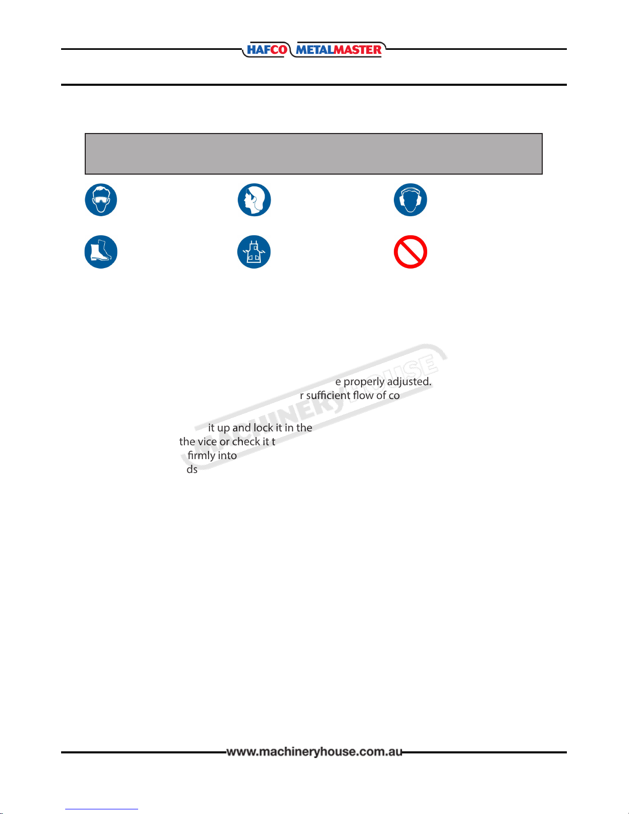
WEARING PROPER APPAREL Do not wear
clothing, apparel or jewelry that can become
entangled in moving parts. Always tie back
or cover long hair. Wear non-slip footwear to
avoid accidental slips, which could cause loss of
operating control.
HEARING PROTECTION. Always wear hearing
protection when operating or observing loud
machinery. Extended exposure to this noise
without hearing protection can cause perma-
nent hearing loss.
REMOVE ADJUSTING TOOLS. Tools left on
machinery can become dangerous projectiles
upon startup. Never leave hex keys, wrenches,
or any other tools on the machine. Always
verify removal before starting!
USE CORRECT TOOL FOR THE JOB. Only use
this tool for its intended purpose. Do not force
the machine or its attachments to do a job for
which they were not designed. Never make
unapproved modications. Modifying the ma-
chine or using it dierently than intended may
result in malfunction or mechanical failure that
can lead to personal injury or death!
AWKWARD POSITIONS. Keep proper footing
and balance at all times when operating ma-
chine. Do not overreach! Avoid awkward hand
positions that make operating control dicult.
This could increase the risk of accidental injury
GUARDS & COVERS. Guards and covers reduce
accidental contact with moving parts or ying
debris. Make sure they are properly installed,
undamaged, and working correctly.
FORCING MACHINERY. Do not force the ma-
chine. It will do the job safer and better at the
rate for which it was designed.
NEVER STAND ON MACHINE. Serious injury
may occur if the machine is tipped or if the
cutting tool is unintentionally contacted
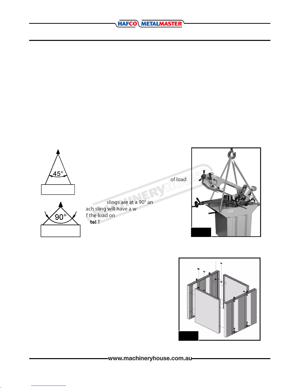
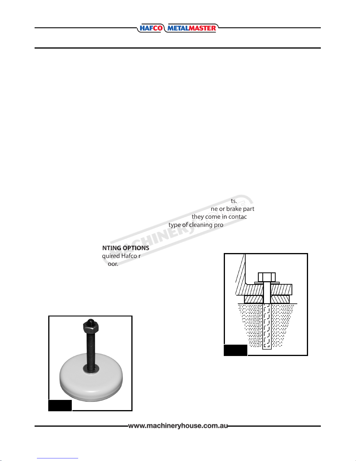
STABLE MACHINE. Unexpected movement
during operation greatly increases risk of injury
or loss of control. Before starting, verify the
machine is stable and if using a mobile base it
is locked in position.
UNATTENDED OPERATION. To reduce the
risk of accidental injury, turn the machine OFF
and ensure all moving parts have completely
stopped before walking away. Never leave the
machine running while unattended.
MAINTAIN WITH CARE. Follow all maintenance
instructions and lubrication schedules to keep
the machine in good working condition. A
machine that is improperly maintained could
malfunction, leading to serious personal injury
or death.
CHECK DAMAGED PARTS. Regularly inspect
the machine for any condition that may af-
fect the safe operation. Immediately repair or
replace damaged or parts that are incorrectly
tted before operating.
CHILDREN & BYSTANDERS. Keep children and
bystanders at a safe distance from the work
area. Stop using machine if they become a
distraction.
BLADE CONDITION. Do not operate with dull,
cracked or badly worn blades. Inspect the
blades for broken teeth before each use.
2.1 GENERAL SAFETY REQUIREMENTS Cont.
Page 7
Instruction Manual for EB-260V (B062V)
04/04/2019

8
OPERATION MANUAL
2.2 SAFETY FEATURES FOR BAND SAWS
DO NOT use this machine unless you have been instructed in its safe use and the
operator has read and understands the instructions in this manual
Safety glasses must be
worn at all times in work
areas.
Sturdy footwear must be
worn at all times in work
areas.
Long and loose hair must
be contained.
Close tting/protective
clothing must be worn.
Hearing protection must
be worn around noisy
machines
Rings and jewelry must
not be worn
PRE-OPERATIONAL SAFETY CHECKS
qLocate and ensure you are familiar with all machine operations and controls
qEnsure all guards are tted, secure and functional. Do not operate if guards are missing or
faulty.
qCheck workspaces and walkways to ensure no slip/trip hazards are present.
qEnsure the hydraulic clamping mechanism functions correctly.
qCheck that the blade is in good condition.
qEnsure the blade’s speed, tension and tracking are properly adjusted.
qCheck coolant delivery system to allow for sucient ow of coolant.
OPERATIONAL SAFETY CHECKS
qLift the head of the unit up and lock it in the upward position.
qSet the angle of the vice or check it to ensure its squareness.
qClamp workpiece rmly into the vice. Long material must be supported.
qAdjust blade guards to cover unused portion of blade.
qEnsure hands are away from the blade, and then turn the machine on.
qAllow the upper head assembly to come down slowly until the teeth are cutting the
material.
qKeep hands away from the blade and cutting area.
qTurn o the machine and bring it to a complete standstill if the blade is to be lifted out of
an uncompleted or jammed cut.
qStop the saw immediately if the blade develops a ‘click’, and check for a broken tooth
qEnsure the saw bow is locked in the upward position before removing workpiece from vice
ENDING OPERATIONS AND CLEANING UP
qSwitch o the machine when work completed.
qReset all guards to a fully closed position.
qBefore removing scrap pieces from the vice area or making adjustments, Stop the machine
and bring it to a complete standstill.
qLeave the machine in a safe, clean and tidy state
DON’T
qDo not use faulty equipment. Immediately report suspect machinery.
qDo not push down on the cutting head while it is cutting.
qNever leave the machine running unattended.
Page 8
Instruction Manual for EB-260V (B062V)
04/04/2019

9
OPERATION MANUAL
2.3 LIFTING INSTRUCTIONS
On the day that the machine arrives, make sure that a crane with sucient capacity is available
to unload the machine from the vehicle. Ensure access to the chosen site is clear and that doors
and ceilings are suciently high and wide enough to receive the machine.
To handle the machine, the slings should be positioned so the machine is level when lifted.
When using slings please take note of the sling angle and the loads that apply.
LIFTING POINTS
Use only the 4 eye bolts supplied with the machine to attach the slings. When lifting the ma-
chine only certied lifting slings should be used. Ensure that when lifting, the machine does not
tip over. Check that the lifting slings do not interfere with the hydraulic pipes or electrical con-
duits. Failure to follow these instructions could cause damage to the machine.
When the slings are at a 45° angle then each
sling is carrying the equivalent of 50% of load
weight. (Fig.2.1).
When the slings are at a 90° angle then
each sling will have a weight equal to 75%
of the load on each sling.(Fig 2.2)
Note! The manufacturer recommends not
to exceed 90° angle
Fig 2.2
Fig 2.1.
Fig. 2.3
2.4 MACHINE STAND ASSEMBLY
To assemble the stand, nd a at even space with plenty
of room to layout the side panels.
qFit the side panels of the machine stand as shown in
the diagram Fig. 2.4.
qPlace the metal belt saw on the machine stand.
qBolt the metal belt saw to the machine stand.
qBolt the drip pan to the machine stand
Fig. 2.4
Page 9
Instruction Manual for EB-260V (B062V)
04/04/2019

10
OPERATION MANUAL
The unpainted surfaces of the machine have been coated with a waxy oil to protect them from
corrosion during shipment. Remove the protective coating with a solvent cleaner or a citrus
based degreaser.
Optimum performance from your machine will be achieved when you clean all moving parts or
sliding contact surfaces that are coated with rust prevented products.
Hafco advise to avoid chlorine based solvents, such as acetone or brake parts cleaner, as they
will damage painted surfaces and strip metal should they come in contact. Always follow the
manufacturer’s instructions when using any type of cleaning product.
3.2 CLEAN - UP
3. SETUP
3.1 SITE PREPARATION
When selecting the site for the machine, consider the largest size of workpiece that will be
processed through the machine and provide enough space around the machine for operat-
ing the machine safely. Consideration should be given to the installation of auxiliary equip-
ment. Leave enough space around the machine to open or remove doors/covers as required
for the maintenance and service as described in this manual.
It is recommended that the machine is anchored to the oor to prevent tipping or shifting. It
also reduces vibration that may occur during operation. The machine should be mounted on
a reinforced concrete oor with a minimum of 150mm thickness. The oor must be able to
support the weight of the machine any workpiece that is to be worked.
3.3 MACHINE MOUNTING OPTIONS
Although it is not required Hafco recommends that you secure
your machine to the oor. Masonry anchors with bolts are the
best way to anchor machinery, because the anchors sit ush
with the oor surface, making it easy to unbolt and move the
machine later, if needed. (Fig. 3.1) Other methods of mounting
is the use of machine mounts which also help with the levelling
of the machine and isolating vibration. (Fig.3.2)
Fig. 3.1
Fig. 3.2
Page 10
Instruction Manual for EB-260V (B062V)
04/04/2019

11
OPERATION MANUAL
Place the machine near an existing power source. Make sure all power cords are protected from
trac, material handling, moisture, chemicals, or other hazards. Make sure there is access to a
means of disconnecting the power source. The electrical circuit must meet the requirements for
240V.
NOTE : The use of an extension cord is not recommended as it may decrease the life of electrical
components on your machine.
3.5 ELECTRICAL INSTALLATION
ELECTRICAL REQUIREMENTS
Nominal Voltage......................................... 240V
Cycle............................................................ 50 Hz
Phase............................................... Single Phase
Power Supply Circuit.............................10 Amps
Full Load Current................................. 6.0 Amps
(Full load current rating is also on the specication plate on the motor.)
3.4 MACHINE LEVELING
To set your machine up so that it operates to optimum performance, apply the following
procedure
After your machine has been anchored to a concrete slab oor, it then needs to be leveled.
Loosen the hold down bolts and place a level on the surface of the working table. Metal shims
need to be placed under corner of the base of the machine until level. Once level then tighten
the hold down bolts. (Fig. 3.3).
The machine must not rest on supports
other than those dened in Fig. 3.1
Metal Shim
Hold Down Bolt
Fig. 3.3
Page 11
Instruction Manual for EB-260V (B062V)
04/04/2019

12
OPERATION MANUAL
The full-load current rating is the amperage a machine draws when running at 100% of the out-
put power. Where machines have more than one motor, the full load current is the
amperage drawn by the largest motor or a total of all the motors and electrical devices that
might operate at one time during normal operations.
Full-Load Current Rating for these machine at 240V is 6.0 Amps
It should be noted that the full-load current is not the maximum amount of amps that the
machine will draw. If the machine is overloaded, it will draw additional amps beyond the
full-load rating and if the machine is overloaded for a long period of time, damage, overheating,
or re may be caused to the motor and circuitry.
This is especially true if connected to an undersized circuit or a long extension lead. To reduce
the risk of these hazards, avoid overloading the machine during operation and make
sure it is connected to a power supply circuit that meets the requirements.
3.6 FULLLOAD CURRENT RATING
4. OPERATION
4.1 CONTROLS FIG.4.1
Fig. 4.1
AB
C
DE
A. OFF Button. When pressed the motor and blade
are stopped.
B. ON Button. When pressed energizes the electrical system
ready to operate when the trigger is depressed.
C. Emergency Stop. When pressed all electrical operating
items will stop. To allow the machine to restart the red
button needs to be twisted to allow the button to pop up.
Now the start button will operate.
D. Coolant Switch. Switches on or o the coolant pump.
E. Speed Control. When turned adjust the speed of the
blade in mtrs/min
Page 12
Instruction Manual for EB-260V (B062V)
04/04/2019

13
OPERATION MANUAL
Fig. 4.2
LIFTUP & SWIVEL HANDLES
The machine is tted with two handles. One to help
when lifting the head and then both handles are used
to help control the head when it needs to be swiveled.
(Fig. 4.2)
TENSIONING THE SAW BLADE
Check the tension of the saw blade. The tension in the
saw blade is correct if the middle of the blade between
the supports, can be pushed down no more than 3 mm
with a force of approximately 50 N.
The tension of the saw blade can be adjusted by means
of the hand wheel. (Fig.4.4)
QUICK ACTION VISE
The band saw is tted with a quick action vise that
allows for the quick tightening or releasing of material
in the vise. The quick action has a limited stroke so the
hand wheel is required to move the vise jaws closer
together.
(Fig. 4.3)
Fig. 4.3
Quick Action
Lever
LENGTH STOP
The machine is tted with an adjustable length stop.
(Fig.4.5)
To install the length stop
1. Screw the threaded rod into the base of the machine
and tighten the lock nut.
2. Slide the length stop onto the rod
3. Measure the distance from the blade to the face of
the length stop and move the length stop in or out
until the correct measurement is achieve.
4. Tighten the length stop on the rod.
Fig. 4.5
Length Stop
Fig.4.4
Page 13
Instruction Manual for EB-260V (B062V)
04/04/2019

14
OPERATION MANUAL
Fig. 4.6
4.2 COOLANT SYSTEM
The sawing movement produces high temperatures
at the edge of the blade due to the friction generated.
The blade must therefore be cooled during operation.
Using a suitable lubricant or cooling agent leads to
better results and longer saw blade life. (Fig. 4.6)
The coolant is delivered through two taps situated on
the blade guide assemble.
To start the coolant turn the switch on the control panel
(D in Fig.4.1) and press and hold the trigger switch, then
adjust the taps. (Fig.4.7 & 4.8) To much ow at the nozzle
will make a mess of the work area and cause it to be-
come unsafe, but to little will cause the blade to over-
heat, causing the blade teeth to load up and break.
Fig. 4.7
Soluble Oils
The most common of all water-soluble cutting uids, soluble oils (also known as emulsiable
cutting uids) are typically 50 percent oil before dilution. When mixed with water, they form a
milky emulsion that is an excellent choice for general purpose cutting. They are, however, prone
to “Monday morning stink”–a foul-smelling odor from microbiological growth of fungus and
bacteria that can grow in your coolant sump if not properly maintained.
Synthetic Fluids
As you can probably guess from the name, synthetics contain no oil, using various polymers
and chemical compounds to replicate oil’s natural lubricity. They reject tramp oil, so they tend
to be the cleanest of all cutting uids, but are often the least lubricious. They are commonly
used in grinding applications, but proponents suggest that synthetics can be tailored to
virtually any metalworking operation, especially metal cutting band saws.
HAFCO recommend that Synthetic cutting oil be used available in two sizes.
5 Ltr Order Code S090
20 ltr Order Code S091
Fig. 4.8
COOLANT SELECTION
Page 14
Instruction Manual for EB-260V (B062V)
04/04/2019

15
OPERATION MANUAL
The upper blade guide should be as close to the workpiece
as possible. This helps ensure straight cuts by keeping the
blade from twisting or drifting o the cut line. (Fig.4.9)
4.3 BLADE GUIDES
Fig. 4.9
Fig. 4.10
Slide Lever
Lock
Adjust the upper blade
guide by loosening the
slide lever lock as in
Fig.4.10
4.4 SETTING THE DOWN FEED
The down feed is the speed at which the saw blade cuts
through the workpiece. The rate at which the bow saw
drops is controlled by a valve that can be adjusted to in-
crease or decrease the speed that it moves.
To set the feed rate raise the bow to the highest position
and hold it in place with the feed ON/OFF lever. (Fig. 4.11)
Adjust the feed rate dial to the desired feed rate.
Start the saw and coolant pump and begin cutting.
Examining the chips is the best indication of the correct
blade speed and feed rate .
A. This is the correct chip shape. The chip should be a
silver colour. If the chips are blue then decrease the
feed until they are silver. The shape also indicates that
the blade TPI is correct.
B. This shape is in-correct. The shape is compressed and
indicates that the chip is too big for the tooth gullet.
This is the most common cause of broken teeth.
Either decrease the feed or change to a larger TPI.
blade.
Fig. 4.11
ON/OFF Lever
Feed Rate Dial
AB
Page 15
Instruction Manual for EB-260V (B062V)
04/04/2019

16
OPERATION MANUAL
4.5 SETTING THE CUTTING ANGLE
The band saw is tted with the capacity to cut angles with the head being able to be
swiveled up to 60° to the right. To set the angle of the cut, raise the bow saw to the high-
est point and hold by setting the ON/OFF lever to OFF.(Fig.4.11). Move the swivel lock lever
(Fig.4.12) to the right and rotate the head until the scale (Fig.4.13) is at the angle required. Move
the swivel lock lever to the left to lock the head. The machine is tted with swivel a head stop at
60 degrees. (Fig.4.14)
NOTE: Please note that the scale (Fig.4.13) is for reference only and if the angle is required to be
very accurate then the angle should be checked with a protractor after the cut.
Fig. 4.16
Fig. 4.15 Fig. 4.17
Fig. 4.13Fig. 4.12 Fig. 4.14
60° Stop
To Swivel The Head To 60 Degrees
Move the swivel lock lever (Fig.4.12) to the right to release the head, then swivel the head until
the pointer is on 60 . (Fig.4.15) The swivel head of the band saw will now be against the 60° stop
(Fig.4.16) . Move the swivel lock to the left to lock the head.(Fig.4.12) To return to a right angle
cut loosen the swivel lock and return the swivel head to the 0°with the head hard up against
the stop.(Fig.4.17) Move swivel lock lever to the left to lock the head
Page 16
Instruction Manual for EB-260V (B062V)
04/04/2019

17
OPERATION MANUAL
Material (m/mm) Feed Motion
per tooth(mm) Material (m/mm) Feed Motion
per tooth(mm)
C10, C15,ST34, ST37
Steel up to 500N/mm 30 ~ 50 0.03 ~ 0.06 Aluminium and Alloy
Aluminium 600 ~ 900 0.04 ~ 0.09
C20, C40, 15Cr3 16MNC35
Steel up to 88 N/mm 20 ~ 40 0.03 ~ 0.04 Aluminium and Alloy
Aluminium (Proles) 800 ~ 1200 0.03 ~ 0.07
38NCD4, 50Cr3,16MnC35
Steel up to 1200 N/mm 15 ~ 25 0.02 ~ 0.03 Brass and Copper 200 ~ 300 0.04 ~ 0.06
Stainless Steel 10 ~ 30 0.01 ~ 0.03 Bronze 400 ~ 600 0.04 ~ 0.08
Casting 30 ~ 50 0.04 ~ 0.05 Synthetic Materials 60 ~ 150 0.04 ~ 0.08
2
2
2
4.6 ADJUSTING THE SPEED OF THE SAW BLADE
Fig. 4.18
The HAFCO EB-260V is tted with a variable speed motor
which is controlled by the rotary dial on the control panel.
(Fig.4.18) The speeds on the dial and in the table below
are an estimate and should be varied to suit the applica-
tion when the blade is running.
CORRECT INCORRECT
4.7 BUNDLE CUTTING.
HAFCO does not recommend that bundle
cutting be done . See the chart as a guide
(Fig. 4.19) to the quick position of the work
piece between the vise jaws to avoid slipping
during cutting
Stacked or bundled steel can slip and cause
the blade to break and may cause injury..
Fig. 4.19
Page 17
Instruction Manual for EB-260V (B062V)
04/04/2019

18
OPERATION MANUAL
4.8 BLADE SELECTION
Band saw tooth size is determined by the size of the cross section to be cut. In general cutting
thinner sections requires more teeth per inch, thicker sections require coarser pitches, or less
teeth per inch. To select an appropriate tooth size please refer to the table immediately below
unless material to be cut is a tube, in which case refer to the larger table below. For general pur-
pose cutting use a constant pitch blade, for more aggressive production cutting of harder to cut
materials use a variable pitch blade.
SOLID SECTION
Section Size (mm) Constant Pitch (TPI) Variable Pitch (TPI)
Up to 10 24 or 18 14/18 or 10/14
10 - 15 14 8 - 12
16 - 30 10 6 - 10
31 - 50 8 5 - 8
51 - 80 6 4 - 6
81 - 120 4 3 - 4
121 - 200 3 1 - 3
Over 200 2 or 1.25 1.4 - 2 or 0.8 - 1.3
Wall
Thickness
(mm)
Outside diameter of tube or maximum prole section length (mm)
20 40 60 80 100 120 150 200 300 500 600 700 800
214 14 14 14 14 14 10-14 10-14 8-12 8-12 6-10 5-8 5-8
314 14 10-14 10-14 10-14 10-14 8-12 8-12 6-10 6-10 5-8 5-8 5-8
414 14 10-14 10-14 8-12 8-12 6-10 6-10 5-8 5-8 4-6 4-6 4-6
514 10-14 10-14 8-12 8-12 6-10 6-10 5-8 5-8 4-6 4-6 4-6 4-6
614 10-14 10-14 8-12 8-12 6-10 6-10 5-8 5-8 4-6 4-6 3-4 3-4
816 10-14 8-12 8-12 6-10 6-10 5-8 5-8 4-6 4-6 3-4 3-4 3-4
10 8-12 8-12 6-10 6-10 5-8 5-8 4-6 4-6 3-4 3-4 3-4 3-4
12 8-12 6-10 6-10 5-8 5-8 4-6 4-6 3-4 3-4 3-4 3-4 2-3
15 6-10 5-8 5-8 4-6 4-6 4-6 3-4 3-4 3-4 2-3 2-3
20 5-8 4-6 4-6 4-6 3-4 3-4 2-3 2-3 2-3 2-3
30 4-6 4-6 3-4 3-4 3-4 2-3 2-3 2-3 2-3
50 3-4 3-4 3-4 2-3 2-3 2-3 2-3 2-3
75 2-3 2-3 2-3 2-3 2-3 1.4-2 1.4-2
TUBE SECTION
Page 18
Instruction Manual for EB-260V (B062V)
04/04/2019

19
OPERATION MANUAL
5 MAINTENANCE
5.2 CHANGING THE BLADE
The blade needs to be changed when it is dull or when
teeth are missing. It also may need to be changed when the
thickness of the material changes.
To change the blade.
1. DISCONNECT THE MACHINE FROM THE POWER SUPPLY.
2. Raise the bow saw for access and turn the feed
ON/OFF lever to hold the bow saw up. (Fig. 5.1)
3. Remove the back cover by removing the 4 knobs
displayed in Fig. 5.2.
4. Slide the upper blade guide as far as possible away
from the lower blade guide.
5. Remove the blade guard on the movable roller guide
by removing the two button head cap screws.
(Fig.5.3)
Fig. 5.1
ON/OFF Lever
Feed Rate Dial
5.1 SCHEDULE
For the best performance of the machine follow the instructions given in this section and fol-
low the schedule laid out below.
Daily Check
qLoose mounting bolts
q Damaged saw blade
q Correct blade tension
q Cutting uid level
q Worn or damaged power
lead
q Any unsafe condition
Monthly Check
qLubricate vice screw
q Check cutting uid levels
Annual Check
qReplace cutting uids and
clean out the tank.
Fig. 5.2
4 Knobs
Fig. 5.3
Button Screws
Page 19
Instruction Manual for EB-260V (B062V)
04/04/2019

20
OPERATION MANUAL
Fig. 5.4
6. Release the tension o the blade by turning the tension
handle clockwise until the blade is loose. (Fig.5.4)
7. Remove the old blade and replace the new blade
making sure that the teeth are facing in th right direc-
tion.
NOTE: Always wear leather gloves when handling cutting
blades. The blades are very sharp and could cause injury to
hands.
8. Re-tension the blade and replace the back cover.
9. Replace the blade guard on the movable roller guide making sure that the blade runs freely
with out touching the guards.
10. Adjust the movable blade guide so that it just clears the work piece.
11. Switch the machine on and make sure the blade is running correctly
5.3 CHANGING THE COOLANT
Fig. 5.5
This band saw is tted with a coolant system that extends
the life of the band saw blade by lowering the temperature
of the blade and the workpiece.
To maintain the eectiveness of the cutting it is important
to keep the coolant clean, therefore the coolant should be
changed every 1000 hrs.
To change the coolant.
1. DISCONNECT THE MACHINE FROM THE POWER SUPPLY
2. Place a container under the drain and remove the
drain plug on the side of the machine. (Fig 5.5)
3. Once the coolant is empty remove the two screws that
secure the screen on the top of the reservoir, and
remove the screen. (Fig.5.6)
4. With clean rags, wipe out the bottom of the coolant
reservoir until it is clean and free from dirt or metal
chips.
5. Replace the screen and drain plug and rele with clean
coolant.
Fig. 5.6
Page 20
Instruction Manual for EB-260V (B062V)
04/04/2019
Table of contents
Other Hafco Saw manuals

Hafco
Hafco BS-10S User manual

Hafco
Hafco BP-430 User manual

Hafco
Hafco MetalMaster BS-5S User manual

Hafco
Hafco MetalMaster CS-315D User manual

Hafco
Hafco TS250SC User manual

Hafco
Hafco EB-351DSA User manual

Hafco
Hafco BS-250 User manual

Hafco
Hafco BP-480 User manual

Hafco
Hafco BS-7DS User manual

Hafco
Hafco BS-7DS User manual

Hafco
Hafco BS-7DS User manual

Hafco
Hafco W434 User manual

Hafco
Hafco MetalMaster CS-315C User manual

Hafco
Hafco T4I BS-250 User manual

Hafco
Hafco BS-460AS User manual

Hafco
Hafco BS-7S User manual

Hafco
Hafco EB-351DSA User manual

Hafco
Hafco BP-305 User manual

Hafco
Hafco MetalMaster CS-350V User manual

Hafco
Hafco BS-13DS Guide