Heat IQ EcoLogic IQ AS7V1Ph Instruction Manual

0
INVERTER HP’s
Operation, installation & maintenance NZ AU.
IQ AS7V1Ph IQ AS10V /1Ph IQ AS15V /1Ph IQ AS20V /3Ph
Installation of this unit must adhere to Local NZ AU
Building Codes and Standards.
Read this manual before installing and or operating the appliance
Please pay particular attention to the sections *
Leave the manual with the end user/appliance
Mitsubishi Compressor inside
PV Integration
compatible
3rd Edition appliances from 1/10/21
By Heat IQ

1
Sectional index
* Pre installation
* System configurations
* Working principal
* Plumbing and electrical connections
User instruction
Engineer and manufacture settings
Detailed operation principals
Maintenance and alarms
Technical information
Sensor resistance tables
Parts identification
Service record
Important note for installers
Compressor crankcase heater
▪This unit is equipped with a compressor crankcase heater which heats the compressor oil and evaporates dissolved
refrigerant before start-up when the outdoor temperature is low.
▪When the outdoor temperature is above 5° and below 10°, The unit must be in a standby state for 1 to 2 hours before
the unit is run for the first time, if the temperature is below 5° for 3 hours and below 2° for at least 6 hours. This ensures
compressor crankcase heater has the compressor oil is at the correct temperature before the FIRST start, ensuring that
no damage is done to the new compressor.
Remember The time you take, and the attention to detail you apply at the time of installation and
commissioning is the key to reliable long term operational service this appliance,
Once you complete the installation, Take some time to show your customer how to use this heating system
this appliance and the associated control devices.
User Maintenance Requirements
To ensure the optimal performance periodic maintenance is essential. Failure to undertake basic maintenance can
reduce the unit performance and shorten the life of the appliance.
1. Make regular checks throughout the year to ensure the inlet grill is not blocked or clogged by leaves, snow or any
other form of restriction.
2. During colder periods check that there isn’t excessive frost or ice building up on or around the unit.
3. Visually check for loose, damaged or broken parts. If such faults are found contact your installer.
4. To maintain the cabinet wipe the surface down regularly with a damp cloth the apply silicone spray or car body wax
5. During the cleaning process, isolate the electrical supply to the appliance.

2
Important Safety considerations - Please read before working on this appliance
To avoid issues that could damage to the appliance or cause injury this appliance must be installed by a suitably
qualified competent contractor. All electrical wiring associated with the appliance must be completed by a
licensed electrical contractor in accordance with NZ / AU Standards.
To reduce the risk of electrical shock. first make the water connections, then electrical connections. If the unit is
to be removed first disconnect the electrical connections, then the water connections
Disconnect at the main power supply before exposing any internal parts of the appliance. In case of malfunction
turn the unit off, isolate the mains power supply and contact a qualified service engineer.
Defects found during installation must be rectified before commissioning. If repairs are carried out then the
operation of relevant safety devices & parameters must be rechecked.
If a refrigerant leak occurs, remove the complete charge using a recovery unit & store the refrigerant in a suitable
for purpose mobile container. When a leak Is rectified recharge the unit with the correct filling weight and Gas
type. This can be found on the appliance data plate.
Ensure the correct refrigerant gas is used to recharge the unit as incorrect gas will cause severe damage to the compressor. Care should be
taken as refrigerant can breakdown due to high temperature, these refrigerants by-products are dangerous.
Do not use oxygen to purge refrigerant lines or to pressurize under any circumstance Oxygen gas reacts violently
with oil, grease and other common substances. Use only dry nitrogen for testing and never exceed the specified
maximum operating pressures.
Do not un-weld or flame cut refrigerant lines or refrigerant circuit components until the entire refrigerant (liquid
and vapour) is removed from unit. Traces of vapour should be displaced with dry nitrogen. Do not siphon
refrigerant. Refrigerant in contact with an open flame will produces toxic gases.
Ensure that the necessary safety protection equipment is available. Have an appropriate fire extinguisher to
hand when working on this appliance.
Take care with refrigerant Avoid spilling liquid refrigerant onto skin or splashing it into the eyes. Use safety
goggles. Wash any spills from the skin with soap and water. If liquid refrigerant enters the eyes, immediately and
abundantly flush the eyes with water and seek urgent medical advice
3 0 °
Movement and Storage prior to installation
This appliance must not be transported, moved or stored
at an angle greater than 30° from the upright position.
Store the unit in a dry area prior to installing.

3
Installation Location
▪This appliance must be installed outside on a concrete pad foundation not connected to the house
foundation.
▪If operating in temperatures below 0°C for prolonged periods or locations where the snow may fall the base
must be raised. we recommend 200 mm above ground to avoid ice build-up on the unit’s chassis.
▪The unit should ideally be placed so that it is well away from bedrooms or noise sensitive areas including
neighbour’s section boundaries. (The unit may produce noise that exceeds a 45 decibel rating).
▪A North facing location aspect will give higher efficiency than a South facing aspect.
▪Make sure discharge water cannot run out onto paths as it may cause ice or slime to build up which is a
Hazard. (The unit is fitted with a collection tray and outlet spigot for waste discharge connection)
▪Avoid locations exposed to machine oil vapour, salt air, thermal springs, sulphur gases or other harsh
substances. In areas with exposure to the above additional treatments must be applied by the installer to
protect the appliance. This will form part of the on-going maintenance regime, the effects of a harsh Costal or
Geothermal atmosphere are not covered by warranty and may shorten the working life.
▪Locations exposed to strong winds should be avoided otherwise baffles may be necessary to deflect strong
winds. Baffles must not restrict air flow & should be at least 2m from the appliance. A baffle is better if it is
not a flat face as this may magnify sound e.g.: a bush is better than a wall
▪The unit must be installed level in both axes (less than 2mm tolerance per meter)
Direct offshore wind
Indirect offshore wind
▪Keep a suitable distance between the unit and the building to ensure normal operation of the appliance and
provide enough room for maintenance.
Clearances
AW12B AW13B AW15B
AW12/H AW13/H
≥1,550mm
≥600mm
≥550mm
≥600mm
A
A=
AS7/10V 200mm
/AS15V 220mm
4
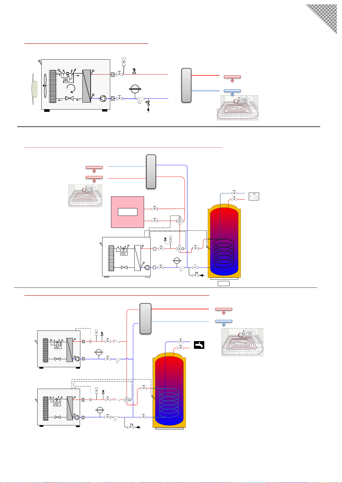
System configuration
System Overview 1: Under-floor heating only.
FI
P1
FI
OT
LPS ET ST
HEAT PUMP
SAK
FL
EXP
Fs
AIV
PT
①
②
③
④
RT
HPS
System Overview 2: Heating, Cooling DHW Production and Boiler back up.
FI
P1
FI
OT LPS ST
RT
HT
VXV
HEAT PUMP
0
BOILER
VXV1
VVB
SAK
F2
F2
FL
EXP
F3
AB
BA
AB
B
A
AIV
ET
Connect to
the indoor
system
PT HPS
System Overview 3: Multiple Units in Series Cascade Connection.
FI
FI
OT LPS PT ST
VXV
HEAT PUMP 2
HT
VVB
SAK
FL
F2
F2
ELK
FI
P1
FI
OT LPS PT ST
RT
HEAT PUMP 1
SAK
NRV
NRV
EXP
FS
A
AB B
FL
EXP
AIV
AIV
ET
ET
ELK
P1
HPS
RT
HPS
Buffer or hydraulic
separator as required
by the system design
Distribution manifold
and pump station as
required by the system
design
Buffer or hydraulic separator as
required by the system design
Distribution manifold
and pump station as
required by the system
design
Buffer or hydraulic separator as
required by the system design
Distribution manifold
and pump station as
required by the system
design
See the key to icons and
working principals for each
schematic set out on next
two pages.

5
Nam
e
Description
Included ?
Nam
e
Description
Include
d ?
P1
Circulation pump
Internal
RT
Inlet water temperature sensor
Internal
VXV
3 way Valve
External
ST
Outlet water temperature sensor
Internal
VVB
Hot water tank
External
OT
ambient temperature sensor
Internal
FI
Soft joint
External
HT
Domestic hot water temperature
sensor sensor
Internal
F2
Shut-off valve
External
PT
Discharge gas temperature
sensor
Internal
SAK
Safety valve
External
ET
Suction gas temperature sensor
Internal
FL
Filter
External
HP
High pressure transducer
Internal
NRV
Non-return valve
External
LP
Low pressure transducer
Internal
ELK
Electric heater
External
EXP
Diaphragm expansion vessel
External
AIV
Air vent valve
External
FS
Automatic water supplement
valve
External
System operation Overview 1 heating only
Heating Mode Working Principle: Same As overview 2 below but there is no three way valve (VXV)
System operation Overview 2 Heating/Cooling/DHW production
Heating mode working principle
When In heating mode, the 3 way valve (VXV) will be in the default open to heating position.
In heating mode, Compressor is On : When the RT sensor drops below (heating set point ST02) by (differential ST04) -Then - The
compressor will turn Off: when the RT sensor is ST02 + 2℃ and running frequency of the compressor has reduced to Minimum for 120s.
T (heating) calculation:
Default ST02 =35, ST06 =0.6
1.) When SF04 =No, there is no heating curve. T (heating) = ST02. 2.) When SF04 = Yes, heating curve is activated,
T (heating) =ST02 +(20 - OT)X ST06. If calculated T (heating) is higher than ST14, ST14 would be T (heating).
Refer to chapter “Heating compensation curve setting”.
Auxiliary Electric backup element, or boiler control (Element included as default in NZ appliances)
The integral auxiliary backup element can only be ON when all of conditions below are met.
1.) Heating mode is operational and the compressor has been running on the maximum workable frequency.;
2.) The compressor has run for over 300s 3.) OT Sensor is below ST07 4.) RT sensor is ST02 is -ST04-2;
The auxiliary backup element is OFF when either of these conditions are met. 1.) A/C flow alarm. -Or- 2.) RT is ST02 - 2
Cooling mode, working principle:
In cooling mode, the 3 way valve (VXV) will open in the default heating position. (Where only part of the overall system is used for cooling
there may be a requirement for further motorised control valve/s to be includes in the system design, these are not covered in this manual)
The compressor is ON when: the RT sensor is over ST01 + ST03(ST01is the control water temperature in cooling mode)
The compressor is Off: when the RT Sensor is below ST01 by 1.5° & running frequency of the compressor has reduced to minimum for 120s.
T (cooling) calculation:
Default ST01 = 13, ST08 = 0.6
1.) When SF04 = No, there is no cooling curve. T (cooling) = ST01.
2.) When SF04 = Yes, cooling curve is activated, T (cooling) =ST01 +(35-OT)X ST08
If calculated T (cooling) is lower than ST11 then ST11 would be T (cooling).
Domestic Hot water production working principle:
In hot water mode, the 3 way valve (VXV) will open to feed the hot water cylinder coil, closing the heating port.
1.) When ST09 is set below ST20
Compressor is turned ON when HT sensor reads ST09-ST10 then - The compressor will turn Off when HT sensor reaches ST09
2.) When ST09 is set higher than ST20
Compressor is turned ON when the HT sensor is below ST20 by ST10 then- The compressor will turn off when HT sensor reaches ST20
So: when DHW set point ST09 is lower than ST20, only the compressor is switched on to produce DHW.
Or: When DHW set point ST09 is higher than ST20, DHW will be heated to ST20 by the compressor, then the managed electric element in
the DHW cylinder will be switched on to raise the DHW up to the ST09 set point.
System operation overview 3: Multiple Units in Series Cascade Connection
Heating working principle
To set two units in parallel operation, set the primary unit to the required parameters, and the other to have a 2~5°C difference of the ST01
and ST02 parameters to allow for energy stage control.
Key

6
INSTALLATION
Pipe - system connections
It is important that you follow the installation information provided here.
Pipework and valve train requirements must be in line with the schematics on page 4 or as prescribed in the
system design provided by the distributor.
1. Installation must adhere to NZ Building & Plumbing Codes, including any local council requirements.
2. Ensure that flow and return pipework is correctly sized for the system and appliance and that they are not
reversed. Reversing the water flow will reduce the output of the unit; refer to the labels on the unit for the
correct water flow direction.
3. Pipe connections must avoid any radial or axial forces to the heat exchanger. Allow some pipe flexibly between
the unit and the structure to reduce any stresses and vibrations issues. Flexible union connections with rubber
gaskets should be used where possible to reduce potential for vibration transmission.
4. Pipework installation must be run to minimise the use of elbows as they can restrict flow. Use bends in
pipework rather than elbows wherever practical to do so.
5. It is essential to insulate all of the system Flow and Return pipe work including HP connections and pipework
within the building, including fittings. This is to protect against both thermal heat loss, impact from frost and
importantly to prevent condensation on chilled pipes where cooling is adopted.
6. Protection devices must be included to protect the appliance from operating outside of its parameters these
must include, air relief valve/s, a 3 bar safety valve, a particulate (Y) strainer on the return and a correctly sized
expansion vessel. Failure to provide any of the above items will void the warranty on this appliance.
7. Isolation service valves must be fitted at the heat pump to facilitate future service requirements. A drain
connection at a low point in the pipework is required to allow the system to be drained if required.
8. Water to fill the system must be clean, and must not contain heavy metals or minerals that could cause harm
to the unit.
Note it is important to ensure that any new heating system installation attached to this appliance is
thoroughly flushed, before connection to this appliance. A system cleaner product such as Kamco Hyper flush
must be used to flush any pre, existing system that this appliance may be attached to.
9. Water within the system must be treated with an approved inhibitor to prevent corrosion, fouling and
deterioration of the system. The inhibitor level should be tested annually, and the dosage maintained. Kamco
System-safe DM & Fernox are approved. Please confirm suitability if you wish to use an alternative product.
Failure attributable to a lack of inhibitor will not be covered by the appliance warranty.
10. A filling loop with braided filling hose, a pressure limiting valve set to 1.3 Bar and gauge should be provided,
such that it will allow the user to easily top up the system pressure. This assembly should not be permanently
connected and active and must include a check valve.
11. For appropriate sizing and set out of A DHW cylinder refer to page 11
Warranty extends to the use of this appliance as prescribed for the purpose for which it is supplied only.
Warranty is void where the appliance is incorrectly installed and or operated.

7
Electrical connections
All voltage connections must only be carried out by a suitably qualified electrician.
Note The Carel HP user interface and RJ10 connection cable are shipped within the HP Cabinet
An additional cable can be ordered seperatly from the regional distributor for install at pre wire.
▪The power supply must conform to the specification on the unit’s nameplate. The supply voltage must be
within the range specified in the electrical data table.
▪For wiring connection, refer to the electric wiring diagram on the inside of the front panel of the unit.
▪RCD breaker protection must be included at the distribution board, according to the max value stated in the
nameplate attached to the appliance.
▪A local isolator switch with a minimum breaking gap of 3 mm must be provided.This switch must not be
mounted directly on to the appliance.
Power supply
IQ AS10V AS15V Are Single Phase appliances. IQ AS20V Requires a Three Phase power supply:
Please refer to the electric wiring diagrams pasted inside the front panel.
Single phase: IQ AS10 and 15V Three phase: IQAS20V
N
PE
L
220-240V/1/50Hz
LN
Mains isolator
Heat pump
terminal
connection
PE
Fuse
Controls and accessory connections
Wired User Interface
The User interface must be installed indoors. about 1.5m up from the floor, (out of
reach of children.) The Standard factory delivered RJ10 Plug in connection cable is
10m. Connect the user interface using this plug in connection cable.
HW Temperature sensor ; for the hot water cylinder:
The domestic hot water sensor (B4) is pre connected to terminal positions B4 and GND on the main board.
This probe must be placed into the hot water cylinder temperature sensor probe pocket if hot water is optioned.
If the domestic hot water sensor cable runs close to power cables, then a shielded cable must be used. If conduit is used then
it should be sealed to avoid condensation forming in the temperature sensor probe.
Important:
Temperature sensor cables must be separated (min 200 mm) from high voltage power cables to avoid interference causing
measured temperature fluctuation & incorrect operation.
380-415V/3/50Hz
L1 L3 N
L2
Fuse
Mains isolator
Heat pump
terminal
connection
PE
8
Control connections continued
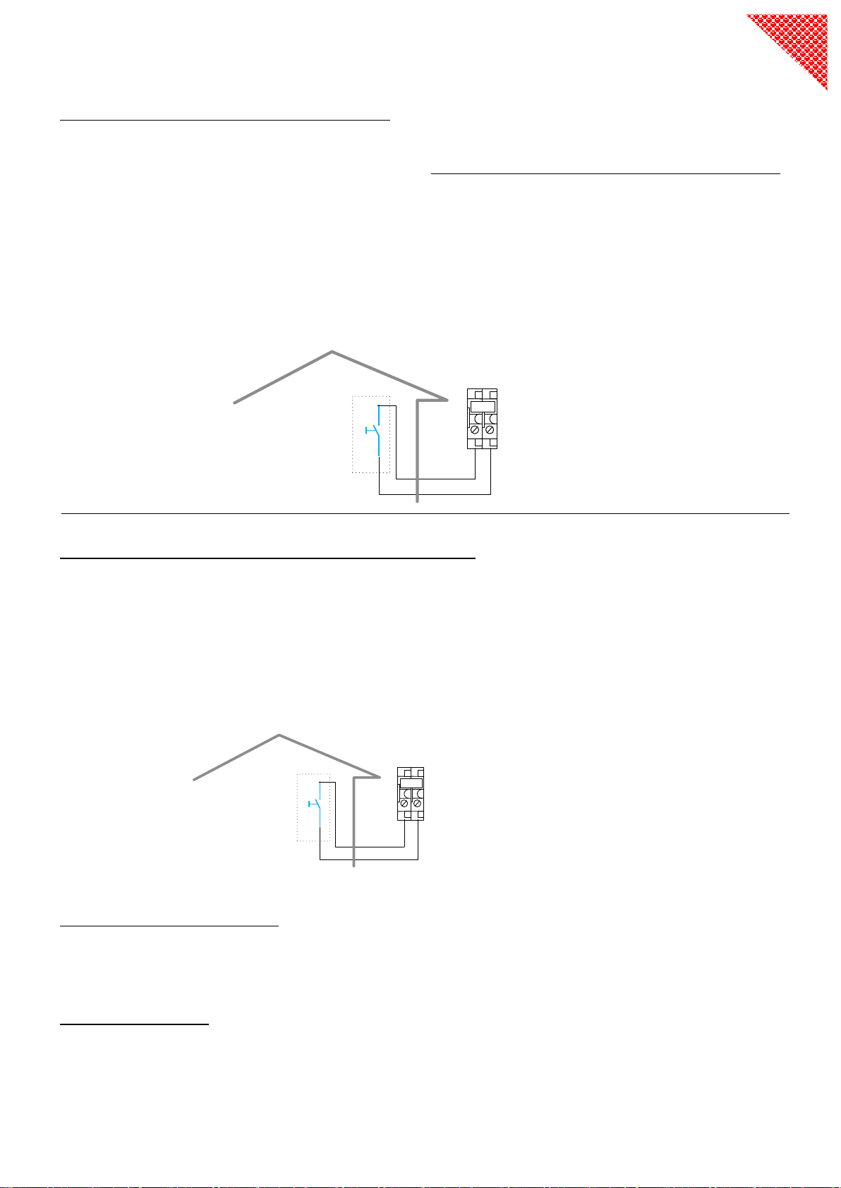
Heating function switching control connections
There are two possible methods to turn ON/OFF the Heating (A/C) function ( settable via SF14)
If SF14 is set to, “keyboard” (the factory default setting). Then external system controls do not control the unit,
the Carel user interface maintains control over the appliance.
If SF14 is set to “remote”. The Carel user interface can no longer be used to turn the heating On or Off. its heating
time zone On/Off function is deactivated. Terminal Connections B1-B2 are now used to turn On/Off the heating,
Via a volt free signal from external system controls
EG; An external signal like a timer, thermostat, or under-floor wiring centre with a volt free switch output are
connected to B1-B2 to activate the unit’s heating function as required. As below
Domestic Hot water function switching control connections
There are two ways to turn ON / OFF the domestic hot water function (Settable via SF13).
If SF13 is set to by “keyboard” then the DHW input is fully controlled by the Carel user interface
If SF13 is set to by “remote” Then DHW demand is controlled by an external control. In this setting the Carel user
interface cannot be used to turn On or Off the DHW and its time zone function is disabled.
If SF 13 is By remote The A1-A2 switch connection in the HP is activated to turn On or Off the hot water function via an
external system control such as a timer wired to it. As below
DHW element control principal:
1.) If ST09 is set below ST20, DHW is only heated by the compressor. If ST09 is set above ST20, compressor stops
heating DHW after HT reaches ST20 , and the element is switched on until HT reaches ST09.
3.) If there is a compressor fault and there is DHW demand, the element is switched on until HT reaches ST09
Legionella protection
4.) The Element is switched on to kill legionella bacteria until HT exceeds ST27, if HT is not over ST27 in the time
interval ST26.
If ST26 = 0, Legionella function is not active. By default ST26 =360 Hr’s this can be set to between 0 and 1000Hrs.
System
thermostat
or other
system
control
Voltage free connection
made at B1 /B2 in HP
System control
over DHW
input
Voltage free connection
made at A1 /A2 in HP
B1 B2
(Manual ON/OFF switch)
A1 A2
(Manual ON/OFF switch)

9
DHW Three Way Valve Connection (NO7 NC7)
Where DHW is optioned A motorised 3 way valve must be used
If the valve used is power open power close then terminals 7-8-9 at the HP are used
If the valve is power open –spring return then only terminals 8 and 9 at the HP are used.
For hydronic connection of the 3 way valve refer to "system overviews"
DHW Reticulation Pulse feed circulation Pump Connection option (N01)
Auxiliary Electric Heater, or Boiler backup.
NZ/Australia all models are equipped with an integral heater (Element) as standard.
The auxiliary heating element is fitted inside the unit, it is connected to the control board via a relay
If the auxiliary element is not fitted, there is a connector on terminal block numbered (3-4) . An auxiliary electric heater or a
boiler could be connected to 3-4 via a relay JQ1 for provision of heating backup. See below.
DHW Cylinder element control
Connector (5-6) are to be used to activate and de-activate the DHW cylinder element for heating domestic hot water this
output must be via a relay JQ2. (not provided)
Important: do not connect elements directly to the terminal block - this will burn-out the controller.
For auxiliary heating electric heater running regulation refer to the section "system overviews”
(Single phase)
(Three phase)
If the domestic hot water is to be reticulated, then our optional DHW circulation pump
can be installed in the domestic hot water reticulation loop connected to cylinder. The
reticulation pump power supply is connected to terminals (1-2) on the terminal block.
DHW circulation pump, operating principal:
1.) When DHW mode is on, the reticulation pump will be switched on and run for a
period of ST34 in every ST33 interval. Eg; 3 minutes every 15 minutes
2.) When DHW mode is switched off, The pump is off after a 3 minute delay.
3 4
JQ1
T
JQ1/2
N
L
PE
ELK
5 6
JQ2
T
JQ1/2
N
L1
PE
ELK
L2
L3
12
P2

10
Typical DHW cylinder set up (standard DHW cylinder or Combi-tank)
It is important to use a cylinder that is fit for purpose. A heat pump delivers coil input at a much lower
temperature and transfers heat with a much lower differential between the body of water and the heating
coil compared to a boiler, wetback or solar. The coil in a cylinder used with a heat pump must have
considerably larger surface area to enable effective heat transfer. If you have a dual coil cylinder you
may connect the two coils together in series for improved input performance
There is nothing to gain from over sizing a DHW cylinder in a heat pump system, a 250L cylinder would be
more than adequate for most homes.
Shown above are a Typical DHW cylinder, and the Heat IQ Eco+ combi tank
Using the conventional cylinder
•The cylinder is piped via a three-way valve from the primary flow and return. these connections for the
cylinder coil F/R are made in the line before the hydraulic separator or buffer tank.
Using the Eco+ Combi tank
• Designed to optimise the energy efficiency of the system in this format a buffer tank within the cylinder
shell has a coil used as a pre heater for DHW. By doing so Combi-Tank® utilises the higher COP energy
from the buffer reducing the requirement for lower COP input through the three way valve to cylinder
coil.
• The efficient option for any system, Combi-Tank® also allows the system the option to input solar PV
energy into both the DHW and the Heating system via elements, for even greater energy efficiency.
• Having both the Buffer tank and Cylinder within a single shell simplifies installation and keeps the system
neat while using less space.
• Combi-Tank® can also be installed with the optional management module for further energy saving
features and user options. (See Combi-Tank manual/brochure)
*When including a Combi-tank® please refer to the specific element control
options in the Combi Tank installation instructions.
PV Ready
Optional

11
Commissioning
Compressor crankcase heater
This appliance is equipped with a compressor crankcase heater to heat the compressor oil and evaporates any
dissolved refrigerant before start-up.
▪When the outdoor temperature is above 5° and below 10°, The unit must be in a standby state for 1 to 2 hours before
the unit is run for the first time, if the temperature is below 5° for 3 hours and below 2° for at least 6 hours. This ensures
compressor crankcase heater has the compressor oil is at the correct temperature before the FIRST start, ensuring that
no damage is done to the new compressor.
Preparations- Filling and Flushing
1. Before commissioning, ensure the whole system has been fully flushed and re filled with fresh water.
2. Check the pipe work in the associated system for leaks.
3. Vent air out the system using the air venting valves.
4. The system must be dosed with an approved inhibitor and set to the required ( 1.1 to 1.5 bar) pressure
We also recommend the inclusion of a biocide dose to prevent contamination of low temp systems
Start-up and Inspection
1. Start the unit by turning on the heating control system and therefore switching on the unit.
2. The water pump will start, then over a period of delay the fan motor, and finally the compressor.
Air in the System after Start-up
▪Air will initially be released from the water as its heated so further venting may be required.
▪If a bubbling sound can be heard from the heat pump, the circulation pump, under-floor and or radiators then
the entire system will certainly require further venting.
Inclusion of a pressure limiting valve set at 1.1 bar as part of the filling loop will allow the system filling point to remain active
throughout commissioning and may be left active for a few days while the system is initially used. It is also a recommended
this valve remains as part of the filling point as this will avoid the potential for over pressure when topping up the system.
The system filling loop should not be left as a permanently open fill point as this will mask any leaks and is non compliant
A permanently connected filling loop may void a claim under the appliance warranty.
Once the system is stable the heating control systems can be fully set as required, and operationally tested.
Frost Protection IMPORTANT
Local climatic conditions are to be considered by the installing contractor.
Requirements for the introduction of glycol are not covered in associated system design provided by the distributor.
It is the installer’s responsibility to ensure adequate consideration is given to requirements for frost protection.
In areas where Temperatures may consistently fall below 0°C A Glycol solution may be required.
1. Add the correct percentage of suitable glycol antifreeze to the water circuit. For example You can purchase
Kamco Freezbreaker from Heat IQ (NZ)
Freezbreaker at a dose of 12.5 % volume in the system gives protection to - 6 / 25% to -12 / 40% to – 20 )
2. Power to the unit must remain on all the times in order that the appliance can start the circulation pump and auxiliary
heater for the integral anti-freeze protection.
Warranty does not cover damage where inadequate frost protection is a contributing factor
(Refer also to installation location instructions)
12
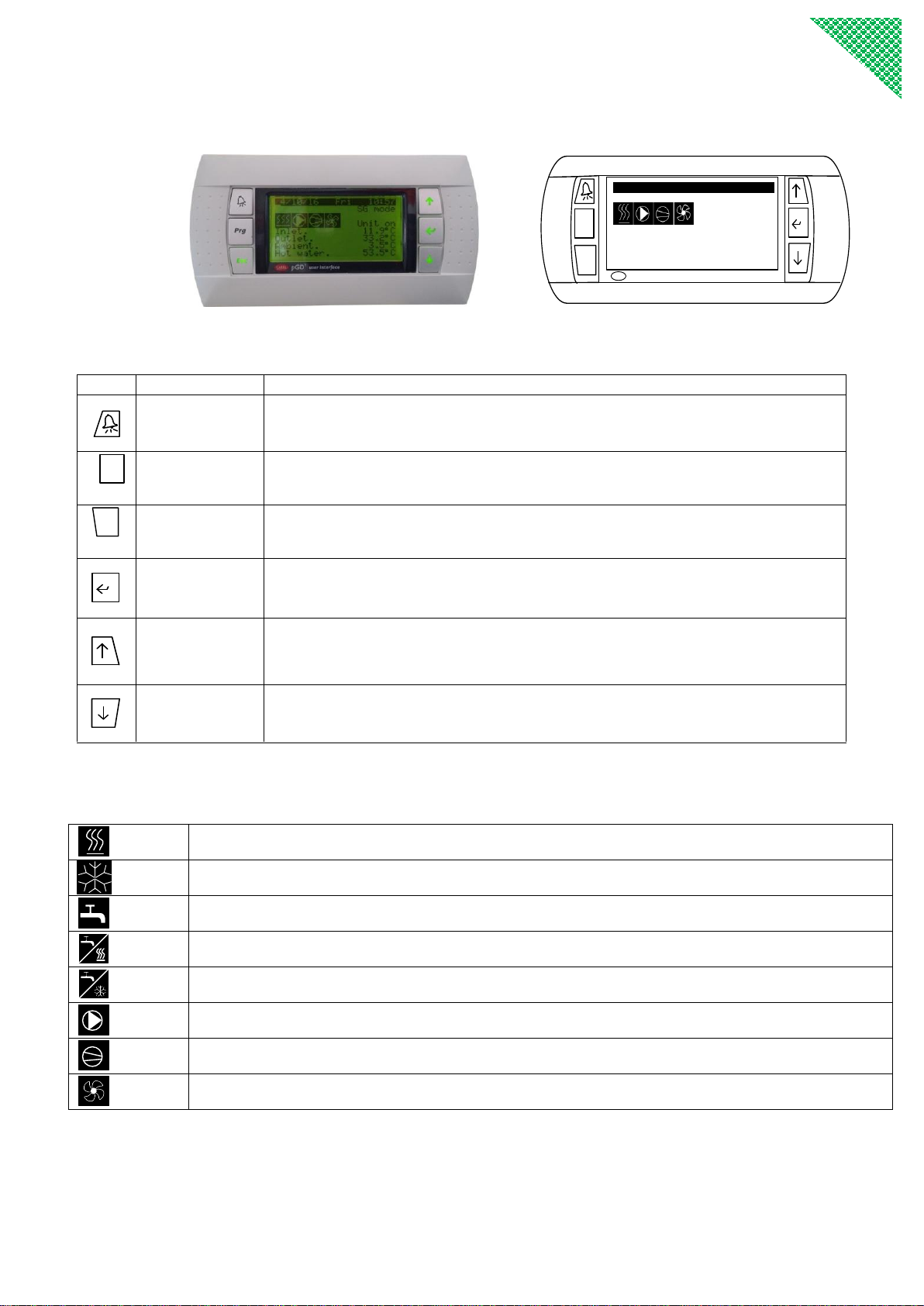
User Guide
(User Interface - Display & buttons)
CAREL p G D1 u ser i n t er fa ce
Prg
Esc
Starting
Inlet. 15.6℃
Outlet. 21.4℃
Ambient . 10.9℃
Hot water. 44.9℃
13/09/15 Sun 15:16
Operating buttons
Button
Name
Operation
<Alarm>
This button will flash to indicate when an alarm occurs.
Press -, to re-set manual re-set alarms, after the fault is removed.
Prg
<Program>
Press to enter main menu
Esc
<Esc>
In Menu /parameter setting mode, press- to return to the previous menu level.
<Enter>
In Menu/parameter setting mode, press to enter the menu, or to save the value entered
or to scroll to the next parameter data.
<Up>
Press to scroll to another menu, or to increase a value in Menu/parameter setting mode
<Down>
Press to scroll to another menu or to decrease a value in Menu/parameter setting mode
In stop, standby or On mode, press it to read actual temp. from inlet water temp. to
outlet water temp………
Symbol explanation
Heating mode
Cooling mode
Domestic hot water mode
Domestic hot water mode + Heating mode
Domestic hot water mode + Cooling mode
Water pump
Compressor
Fan

13
Interface Menu Tree
Menus
Parameter
CM01
CM
CM02
CN01
CN
CN02
EV05
EV
EV06
SF06
SF07
SF
SF09
UI02
UI
AR01
AR02
AR
AR11
CN08
User
I/O
input/output
Unit on/off
ST01
ST
ST02
DF
DF02
DF03
DF15
Clock Alarm
history
Manu-
facturer Service
ST10 EV14
ST11
ST12
ST
ST16
UI01
UI
EV01
EV
EV03
SF01
SF05
SF
SF14
EV04 SF13
Code
Relates to
Code
Relates to
CM
Compressor settings
ST
Setpoints
CN
Condenser settings
UI
User interface
EV
Evaporator settings
AR
Alarm settings
SF
Special functions
DF
Defrost settings
Three access groups, with different privilege levels are applied.
Privilege Level
Main Activities, Special
All
Manufacturer
•Password required
•Configure and commission applications by setting/adjusting
parameter values
•View information and status
•Acknowledge warnings and alarms
•Heating /Cooling changeover
Service
•Password required
•Configure and commission applications by setting/adjusting
parameter values
User
•No password is required
•Adjust User parameters
How it works
FI
P1
FI
OT
LPS ET ST
HEAT PUMP
SAK
FL
EXP
Fs
AIV
PT
①
②
③
④
RT
HPS
1. Low pressure, low temperature liquid refrigerant coming out of the expansion valve exacts heat energy from the air
passing through a densely finned coil heat exchanger ① and evaporates into a gas state.
2. The gas state refrigerant is sucked into the compressor ②compressed to high pressure and high temperature gas.
3. This high pressure, high temperature gas is discharged, and the compressor releases its heat energy transferring it to
water via the plate exchanger ③ as this happens the gas is condensed to liquid state.
4. The now liquid state refrigerant is expanded in thermostatic expansion valve ④ and again becomes low pressure and
low temperature liquid refrigerant and the cycle repeats.
14
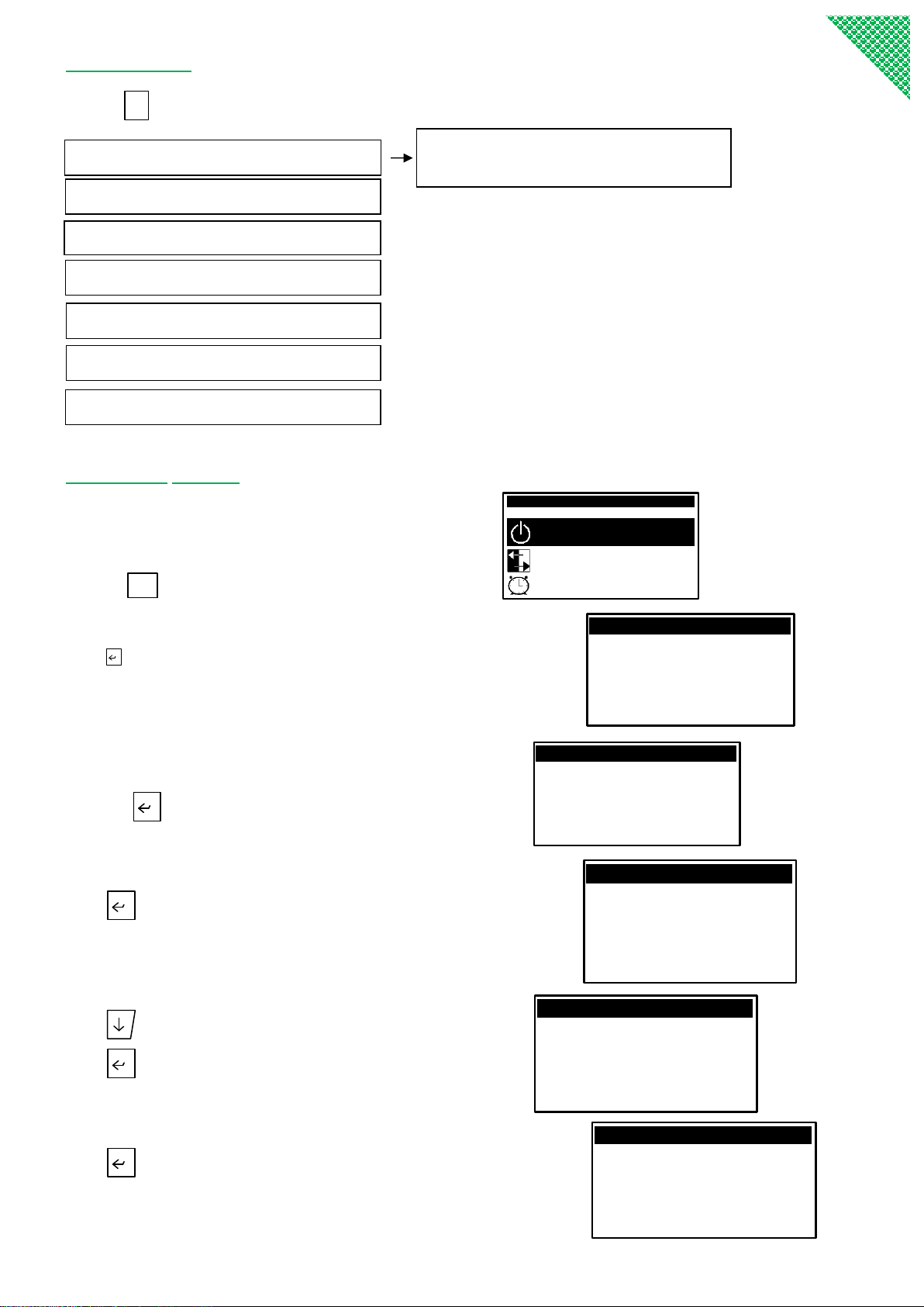
Main menu:
Press
Prg
button to enter main menus:
Unit on/off setting. (When the appliance on/off method is by keyboard)
Press
Prg
button. The display shows -
M ain m enu 1 /7
A. Unit On/off
B. Input/Output
C. Clock
Press button, the display shows the unit current heating (AC),
and domestic hot water (DHW) On/Off status.
If the set mode is heating (not cooling), it displays AC status (heat).
The “OFF” icon flashes on AC status (heating),
press the button, it will display Sure to switch on:
Press button to enter.
The display indicates AC (heating) is now On:
Press button, the “OFF” on HW status flashes,
press button, it will display: sure to switch on
press button to enter, it will now display HW On
A. Unit on/off A/C(heating) & DHW
B. I/O input/output
C. Clock
D. User
E. Service
F. Manufacturer
Remark: this will not appear if unit on/off for
heating or hot water method is by remote.
G. Alarm history
Continues next page
AC status(heat): OFF
HW status: OFF
Sure toswitch on?
Unit On/off
AC status(heat): O N
HW status: O N
Unit On/off
AC status(heat): OFF
HW status: OFF
Unit On/off
AC status(heat): O N
HW status: OFF
Unit On/off
AC status(heat): O N
HW status: OFF
Sure to switch on?
Unit On/off

15
A/C (Heating) and DHW are now successfully switched on. “Starting” displays on the screen, the water pump turns on
and the pump symbol displays on the screen. Within some minutes of delay, the fan and compressor will turn on and
their respective symbols will also display the on screen. Switching the unit Off is same operation.
The Appliance can also be switched on/off via Remote switches to A1-A2 (hot Water), and, B1-B2, (Heating). Refer to
chapter power connections – We recommend the use of remote switching from the heating via B1 B2 as the default
control method. Note; in this format you will not able to turn AC (Heating) on or off at the User interface.
In operation, inlet temp, outlet temp, ambient temp, etc, can be checked via pressing up and down buttons.
I/O input/output This menu displays the unit measured temperature sensors value, digital switch on/off state,
components on/off state.
Changing System mode – from Heating to Cooling
System mode can only be changed on heating/cooling units
(SF01 unit type setting = cooling + heating).
Button Operation: Prg User System mode
When the unit is in an off state, press “Prg” to enter main menu,
press up or down button to User, then press Enter -, it displays:
Press the Enter button, Heating will flash, press the up or down
button to change to Cooling,
Press the Enter button to confirm. - It will display:
B1
RT
AC inlet temp
B2
ST
AC outlet temp.
B3
OT
Ambient temp.
B4
HT
Hot water temp.
B5
PT
Discharge temp.
B6
LPS
Suction pressure
B7
HPS
Discharge pressure
B8
ET
Suction temp.
B9
PWM
Pump duty ratio
DI4
AC switch
DI5
DHW switch
DI6
SG1
DI7
SG2
NO1
DHW circulation pump
NO2
Indoor pump
NO3
4-way valve
NO4
AC heater
NO5
Crankshaft heater
NO6
Inject valve
NO7
3-way valve
N08
DHW heater
N09
De-icing. heater
Y1
EC fan
Y3
Indoor pump PWM
System mode
Heating
S01
System mode
Cooling
S01
16
Changing Set points (user parameters)
Display
Procedures
Main menu 4/7
A. Unit On/off
B. Input/Output
C. Clock
D. User
Press <Prg> to display the main menu, press Down button to User, Press the
Enter button, Press the Down button to the desired parameter.
ST 01:Cooling 13.0
ST 02:Heating 40.0
Setpoint S02
Press the Enter button, when cursor is flashing on say 13.0℃, press Up or
Down button to change the value.
Press Enter to confirm setting or move to the next parameter.
Cursor will move to next parameter data shown here as 40.0℃ ,
this can also be changed via use of the up or down buttons.
Press Enter to confirm,
Cursor will move to set point S02,
When cursor is flashing on set point S02, use the down button to move to
the next parameter.
Or, continuously press <Esc> to exit out of the current level and back to the desired menu level.
User Parameter, Table.
Para-
meter
Descriptions
De-
fault
Min.
Max.
Unit
Res
mode
Cooling or heating
heating
ST01
Setting temperature on Cooling mode
13
ST11
ST12
ºC
0.1
ST02
Setting temperature on heating mode
35
ST13
ST14
ºC
0.1
ST03
Setting temperature difference on Cooling mode
2
1
10
ºC
0.1
ST04
Setting temperature difference on Heating mode
2
1
10
ºC
0.1
ST06
Compensation factor for heating curve
0.6
0
3
-
0.1
ST07
Ambient temperature condition for starting the boiler or
Auxiliary backup electric heater
0
-10
20
ºC
0.1
ST08
Compensation factor for cooling curve
0.6
0
3
-
0.1
ST09
Setting temperature on domestic hot water mode
50
ST15
ST16
ºC
0.1
ST10
Setting temperature difference on domestic hot water mode
3
1
10
ºC
0.1
ST17
SG function: Cooling/heating water temperature
decrement/ increment
2
1
10
ºC
0.1
ST18
SG function: DHW water temperature increment
5
1
10
ºC
0.1
ST33
DHW circulation pump off interval
15
0
180
min
1
ST34
DHW circulation pump running time
3
0
180
min
1
TR09
Heating (AC) time zone On/Off
disable
Disable or enable
TR10
DHW time zone On/Off
disable
Disable or enable
SF04
Weather compensation function
No
Yes or No
User parameters can be adjusted when the unit is either in an ON or OFF state.

17
Time-zone on/off
The time-zone function activates the pre-set timer programs. A time-zone function is only valid when unit on/off
method is “by keyboard”.
TR10: HW time-zone is for domestic hot water. When TR10 is enabled, two different time periods are available to set
in every day from Sunday to Saturday.
After setting for Mondays times scroll to “Monday” and press up or down button to change to Tuesday to set its timer,
and so on. If the ON and OFF data are set the same, the timer function is not activated.
TR09:AC timer-zone is for A/C (Heating) When TR09 is set to Enable, two different time periods for each day from
Sunday to Saturday. Typically Heating control is by from the system (by remote) so Heating timing is not required.
If every day’s time-zone setting is to be the same, you do not need to set day by day, just go to
Change Monday to Tuesday, and change “No” to “Yes”, then Tuesday’s time-zone setting will be same as Monday.
Use the same method to change Wednesday, etc.
If the unit is manually turned on by the user at the keyboard before the automatic turning on by the timer, this timer
ON program is implemented and unit will be turned off automatically when the time setting reaches the next
programmed off time. (The same applies to manually turning off)
-------------------------------------------------------------------------------------------------------------------------------------------------
S19 Displays the total compressor operating hours.
S20 Allows the re setting of the user settings back to the factory default – To action Change no to yes press enter
Operating hours
0 hour
Compressor S19
Insert user default
NO
S20
TR09:AC timezone
Disable
TR10:HW timezone
Disable
Timezone on/off S08
Monday
ON OFF
AC -1 00:00 00:00
AC -2 00:00 00:00
Timezone on/off S09
Monday
ON OFF
HW-1 00:00 00:00
HW-2 00:00 00:00
Timezone on/off S09
Timezone on/off
Monday:
Copy from Monday
Confirm: NO

18
Weather compensation
Heating – Weather compensation curve setting
Note this function is not appropriate in all applications
Users: Seek professional advice before attempting to set weather compensation
There are two methods for temperature control: fixed and changeable temperature. Fixed temperature is a fixed value
and directly set by the user from the settings area. Changeable (Compensated) temperature is determined by the
values of ST02, ST06 and the actual outdoor temperature measured by the OT sensor probe.
The Changeable (Weather compensated) function is selected using SF04:
When SF04: ENABLE COMPENSATION = NO, it is fixed temperature;
When SF04: ENABLE COMPENSATION = YES, it is weather compensated changeable temperature.
Set temperature at heating = ST02 + ST06 *(20-OT).
● ST02 is the indoor temperature that the user requires to feel comfortable.
● ST06 is the heating compensation coefficient curve factor that you select for the heat pump to work with.
Increasing the ST06 set point will increase the compensation temperature and RT will increase relatively. ST06 is
adjustable in a range from 0.6 to 3.0 Degrees.
● OT is the current outside temperature.
The calculated temperature can be used for the control reference, but the maximum data must not exceed ST14
For example:
If you set the heating compensation coefficient ST06 = 0.5 Deg, ST02 = 20Deg
1.) When outdoor temperature is 0℃, the control temperature is ST02 + ST06 *(20 - OT) = 20+0.5*(20-0 ) =30℃;
2.) When outdoor temperature is -10℃, the control temperature is
ST02 + ST06* (20-OT) = 20+0.5* (20- (-10) )=35℃;
3.) When outdoor temperature is –20℃, the control temperature is
ST02 + ST06* (20-OT) = 20+0.5* (20- (-20) )=40℃;
Calculated result as above could be checked from curve below.
0.7
0.5
0.3
Outside temperature (OT)
Control temperature T(heating)
2 1.7 1.5 1.3 1.1 0.9
℃
60
50
40
30
Heating curve ST02=20℃
ST06
10 0 -10 -20 -30℃
With a drop of the outdoor temperature, the control temperature becomes higher to meet the larger heating
requirement.
With the increase of the outdoor temperature, the control temperature becomes lower, so that the heat pump works
at a lower pressure reducing energy consumption.
19
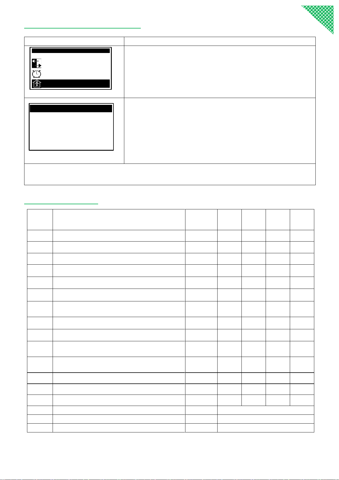
Changing either ST02 or ST06 will change the heating curve.
Increasing ST02 will lift up the curve
℃
70
60
50
40
30
10 0 -10 -20 -30℃
Outside temperature (OT)
Control temperature T(heating)
Increasing ST06 will increase the grade of the curve
℃
70
60
50
40
30
10 0 -10 -20 -30℃
Outside temperature (OT)
Control temperature T(heating)
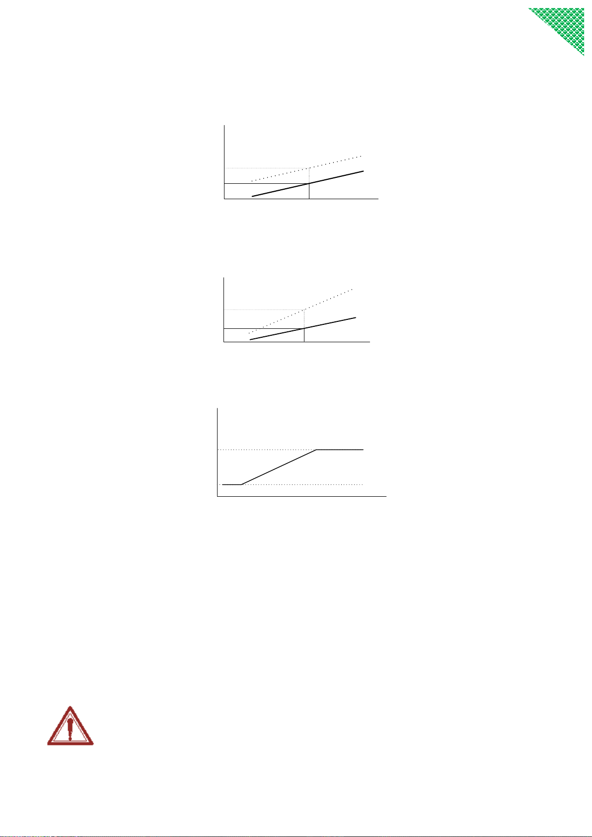
The calculated control water temperature will not be allowed over ST14,or under than ST13.
℃
70
60
50
40
30
10 0 -10 -20 -30℃
Outside temperature (OT)
Control temperature T(heating)
ST14 Maximum heating temperature
ST13 Minmimum heating temperature
Cold weather conditions
●When the room temperature is too low, you could increase ST06.
●When the room temperature is too high, you could decrease ST06.
Warm weather conditions
●If the room temperature is too low, you could increase ST02.
●If the room temperature is too high, you could decrease ST02.
NOTE: The temperature of a room with floor heating requires a long time to stabilize. After making
any ST02 ST06 adjustment, wait 24 hours to assess before making further adjustments.
This manual suits for next models
3
Table of contents


-L5 Series installation manual")


