Mastervolt International B.V. P.O.Box 22947, NL-1100 DK Amsterdam, The Netherlands. Tel.: +31-20-3422100 Email: info@mastervolt.com Web: www.mastervolt.com March 2004
DEUTSCH
Produktbeschreibung und Anwendung
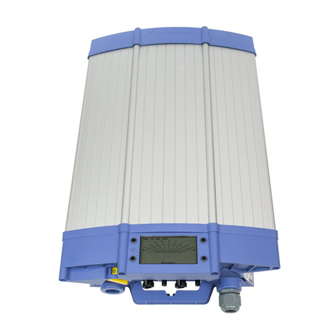
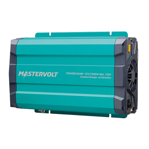
Der MASS Sine 12/400 und 24/400 formen 12 oder 24V Batteriespannung um in 230V, mit einem
stabilen 50 Hz Frequenz. Die Wandler sind geeignet zur Speisung von Notebooks, Lampe, Handy-
Lader, usw. Schützen Sie den Wandler gegen Regen, Kondenswasser, Feuchtigkeit und Staub.
Installation
1. Installieren Sie den Wandler in einem gut belüfteten Raum möglichst nahe bei den Batterien. Im
Hinblick auf eine eventuelle Ansammlung von Feuchtigkeit und für eine optimale Wärmeableitung
empfehlen wir, den Wandler mit den Anschlusskabeln nach unten zu montieren.
2. Schließen Sie das Minuskabel (schwarz) an den Minuspol (-) der Batterie an und das Pluskabel
(rot) an den Pluspol (+). Die DC Bekablung soll mit einer Sicherung wie angedeutet unter
Specifications geschützt werden.
3. AC Anschluss. Die Verbrauchergeräte können direkt am EURO Steckdose (3) angeschlossen
werden. Eventuell den mitgelieferten Stecker verwenden.
Betrieb
1. Nach Montage kann der Wandler durch Betätigung des Schalters (1) auf “ON” angeschaltet werden.
Mit diesem Schalter kann das Gerät auch nach langfristiger Überlast reset werden (Siehe
Specifications).
2. Wenn Sie den Schalter (1) auf “AES” stellen, können Sie den Automatic Economy Switch aktivieren.
Weniger Stromverbrauch von der Batterie wenn nicht belastet. Nicht alle Belastungen
erwirtschaften diesen Vorteil. Bitte versuchen Sie ob sich dies für Sie lohnt.
Anzeigen
Der Wandler hat eine LED-Anzeige (2). Kontinuierlich grün heißt normaler Betrieb. Sollte der LED
flackern oder von Farbe wechseln, bitte checken Sie den Zustand wie angegeben unter Specifications.
Sicherheitsvorschriften und -maßnahmen
1. Installieren Sie den Wandler gemäß den genannten Anweisungen.
2. Benutzen Sie den Wandler nie in einer Umgebung, in der die Gefahr einer Gas- oder
Staubexplosion besteht.
3. Anschlüsse und Sicherheitsvorkehrungen müssen den lokalen Vorschriften entsprechend
ausgeführt werden.
4. Durch Verpolung Zerstören Sie den Wandler. Kontrollieren Sie deshalb ob alle Verbindungen
korrekt angeschlossen sind, bevor Sie den Wandler einschalten.
Garantiebestimmungen
Mastervolt garantiert, dass die Wandler unter Einhaltung der gesetzlichen Normen und Bestimmungen
gebaut sind. Bei der Herstellung und vor der Lieferung werden alle Wandler eingehend getestet und
kontrolliert. Wenn die in dieser Gebrauchsanleitung beschriebenen Vorschriften, Anweisungen und
Bestimmungen nicht beachtet werden, können Schäden entstehen und/oder kann das Gerät nicht den
Spezifikationen entsprechen. Das bedeutet, dass die Garantie verfällt.
Die Garantiezeit beträgt 2 Jahre
Haftung
Mastervolt kann nicht haftbar gemacht werden für:
•Durch die Benutzung des Wandlers entstandenen Schaden,
•Eventuelle Fehler in der dazugehörenden Anleitung und die daraus entstehenden Folgen.
•Einen anderen Gebrauch, d.h. einen Gebrauch, der nicht mit der Bestimmung des Produkts
übereinstimmt.
ITALIANO
Descrizione del prodotto e applicazioni
Gli inverter Sine 12/400 e 24/400, convertono la tensione DC in AC sinusoidale pura a 230V/50Hz per
alimentare piccole utenze come laptops, luci, caricabatterie per cellulari, ecc.. Gli inverter devono
essre protetti dalla pioggia, vapori, salmastro e polvere, e installati all’interno il luoghi asciutti.
Installazione
1. Installare l’inverter in un'area ben ventilata il più vicino possibile alle batterie. Consigliamo di
montare le unità in verticale, con i cavi di collegamento rivolti verso il basso. Ciò evita l'accumulo di
umidità e agevola la dispersione del calore.
2. Il cavo negativo (–), nero, va collegato al polo negativo della batteria ed il cavo positivo (+), rosso, al
polo positivo. Assicurarsi che la linea sia protetta da un fusibile di adeguata taratura.
3. Tensione AC: il carico può essere collegato direttamente alla presa Euro (3). Se l’utenza non ha
una presa Euro, può essere installata usando l’adattatore fornito di serie.
Istruzioni per l'uso
1. Dopo l’installazione, l’inverter può essere acceso ponendo l’interruttore (1) in “ON”. L’interruttore ha
anche una funzione “reset” per riavviare l’inverter in caso di blocco per sovraccarico (vedi
specifiche).
2. Ponendo l’interruttore (1) in “AES” attiva la funzione AES (Automatic Economy Switch) per ridurre
l’autoconsumo dalle batterie a vuoto. La AES controlla la linea e quando un carico AC viene inserito
eleva automaticamente la tensione a 230V . Non tutti i carichi sono facilmente induviduabili. La
funzione AES viene usata solo se ci sono effettivi benefici.
Indicazioni
L’inverter è dotato di un indicatore luminoso a LED (2). In condizioni normali il LED è verde. In caso di
condizioni critiche, che richiedono attenzione, il LED lampeggia o cambia colore. Nelle specifiche si
può indiviare il codice che indica il tipo di guasto.
Prescrizioni e misure di sicurezza
1. Effettuare la messa in opera in osservanza alle istruzioni fornite.
2. Non utilizzare mai l’inverter in presenza di gas o in aree a rischio di esplosione.
3. I collegamenti ed i dispositivi di protezione devono essere realizzati in conformità alle norme
localmente vigenti.
4. In caso di inversione della polarità dovuta allo scambio dei cavi sulla batteria, l’inverter può essere
gravemente danneggiato. Verificare che tutti i collegamenti siano stati effettuati correttamente prima
di accendere l’inverter.
Garanzia
La Mastervolt garantisce che gli inverter di sua produzione sono stati costruiti secondo le norme e
disposizioni applicabili. Durante la produzione e prima della consegna, tutti gli inverter sono sottoposti
a severi test e collaudi. Il non attenersi alle prescrizioni, istruzioni e disposizioni riportate nella
presente guida, può causare danneggiamenti e/o la mancata rispondenza degli apparecchi alle
specifiche, circostanze che possono causare il decadere del diritto alla garanzia.
La garanzia ha una validità di 2 anni.
Responsabilità
La Mastervolt declina ogni responsabilità per:
•Danni derivanti dall'utilizzo dell’inverter.
•Eventuali errori o omissioni nelle istruzioni per l'uso e le conseguenze che ne derivano.
•Un utilizzo del prodotto non conforme allo scopo previsto.
FRANÇAIS
Description et application
Les convertisseurs Mass Sine 12/400 et 24/400 convertissent la tension CC en tension CA pure
sinusoïdale de 230V/50Hz pour fournir de petits équipements tels qu’ordinateurs portables, ampoules,
téléphone portable etc. Le convertisseur doit être protégé de la pluie, la vapeur, l’humidité et la
poussière et doit donc être utilisé dans des endroits secs, à l’intérieur.
Installation
1. Installer le convertisseur dans une pièce bien ventilée le plus près possible des batteries. Nous
vous conseillons de monter les appareils avec les câbles de connexion vers le bas afin d’éviter une
accumulation d’humidité et de chaleur.
2. Connecter le câble négatif (noir) à la borne négative (–) et le câble positif (rouge) à la borne positive
(+) de la batterie. Vérifier qu’un fusible CC est intégré au câblage conformément aux valeurs
spécifiées.
3. Tension CA : l’utilisation peut être connectée directement à la prise Euro (3). Si l’équipement ne
comporte pas de prise Euro, la fiche séparée peut être utilisée pour faire un câble adaptateur.
Fonctionnement
1. Après l’installation le convertisseur peut être mis en route en positionnant l’interrupteur (1) sur
« ON ». L’interrupteur est également doté d’une fonction reset pour redémarrer le convertisseur
après une surcharge importante (voir spécifications)
2. En positionnant l’interrupteur (1) sur “AES” l’Automatic Economy Switch est activé afin
d’économiser l’énergie de la batterie en mode arrêt à vide. L’AES met en route automatiquement le
230 V lorsqu’il détecte une charge AC. Malheureusement toutes les charges ne peuvent pas être
détectées. Il ne coûte rien d’essayer l’AES de toutes façons.
Indicateurs
Le convertisseur est doté d’un indicateur LED (2). En utilisation normale, ce voyant vert est allumé. En
cas de problème, le voyant clignote ou change de couleur. Reportez-vous aux spécifications afin de
déterminer la cause du problème.
Consignes et mesures de sécurité
1. Installer le convertisseur conformément aux instructions indiquées.
2. Ne jamais utiliser les convertisseurs dans un lieu où existe un risque d’explosion de gaz ou de
poussière.
3. Raccordements et sécurisations doivent être effectués conformément à la réglementation locale en
vigueur.
4. En cas d’inversion des connexions positive et négative sur la batterie, le convertisseur peut être
sérieusement endommagé. Vérifier que toutes les connexions sont faites correctement avant de
mettre le convertisseur en marche.
Conditions de garantie
Mastervolt certifie que les convertisseurs sont fabriqués conformément aux normes et disposition
légales en vigueur. Tous les convertisseurs sont minutieusement testés et contrôlés pendant leur
production et avant leur livraison. L’utilisation non conforme aux consignes, instructions et dispositions
fournies dans ce manuel d’utilisation peut entraîner des dommages et/ou l’appareil ne répondra pas
aux spécifications. Ce qui peut donner lieu à l’annulation de la garantie.
Le délai de garantie est de 2 ans.
Responsabilité
Mastervolt décline toute responsabilité dans les cas suivants :
•Dommage survenu suite à l’emploi du convertisseur
•Eventuelles erreurs dans le manuel correspondant et leurs conséquences
•Utilisation considérée non conforme à celle prévue.
ESPAÑOL
Descripción del producto y aplicaciones
Los inversores Sine 12/400 y 24/400 convierten el voltaje CC en una tensión senoidal pura de
230V/50Hz, para hacer funcionar ordenadores portátiles, bombillas o bien cargar teléfonos móviles.
Deben de ser protegidos contra la lluvia, la condensación, la humedad y el polvo. Por lo tanto, sólo se
pueden utilizar en espacios interiores y secos.
Instalación
1. Instale el inversor en un espacio bien ventilado, lo más cerca posible de las baterías. Aconsejamos
montar las unidades con los cables de conexión hacia abajo, a fin de evitar una posible
acumulación de humedad y procurar una disipación de calor óptima.
2. Conecte el cable negativo (negro) al polo negativo (-) de la batería. El cable positivo (rojo) debe ir
conectado al polo positivo (+) de la batería. Asegurése de proteger el cableado de la corriente
continua (CC) con un fusible, tal como se indica en este manual de instrucciones
3. Voltaje CA: se puede conectar la carga directamente, a través del euroconector (3). Si el aparato
no dispone de este enchufe, se podrá utilizar el conector suministrado con el inversor adaptándole.
Funcionamiento
1. Después de instalar el inversor, se podrá poner en marcha, apretando el interruptor en “ON”. Este
interruptor permite también hacer un reset para volver a poner en marcha el inversor después de
una sobrecarga importante (ver especificaciones).
2. Apretando el interruptor (1) en “AES” activa el sistema AES (Sistema de Ahorro de Energía), para
ahorrar energía de la batería cuando no hay ninguna carga. El sistema AES escanea
periódicamente la línea CA para detectar si hay cargas conectadas. En este caso, pasa
automáticamente a 230V. Sin embargo, todas las cargas no son fáciles de detectar.
Indicaciones
El inversor está equipado con un testigo luminoso tipo LED (2), que se encenderá de color verde en
funcionamiento normal. En caso de situación anormal el testigo luminoso empezará a parpadear o
cambiar de color. Para conocer el código de error, refiérese a las especificaciones, donde encontrará
la lista de códigos de errores.
Prescripciones y medidas de seguridad
1. Instale el inversor según las instrucciones indicadas.
2. No utilice nunca un inversor en un recinto con peligro de presencia de gas o explosiones de polvo.
3. Las conexiones y medidas de seguridad siempre se deben de llevar a cabo de acuerdo con la
normativa vigente en el país en cuestión.
4. Al invertir las conexiones positiva y negativa de la batería, se puede dañar gravemente el inversor.
Compruebe que todas las conexiones sean las adecuadas antes de poner en marcha el inversor.
Garantía
Mastervolt garantiza que los inversores senoidales están construidos conforme a las normas y
disposiciones legales vigentes. Durante la fabricación y antes de su entrega todos los inversores han
sido sometidos a diversos controles y pruebas. Si al utilizar el inversor no se respetan las
prescripciones, indicaciones y disposiciones recogidas en este manual, puede producirse daños en el
mismo y/o el aparato no cumplirá las especificaciones indicadas, lo cual puede implicar la anulación
de la garantía. La garantía tiene un periodo de validez de 2 años.
Responsabilidad
En ningún caso Mastervolt asumirá responsabilidad alguna derivada de:
•Daños producidos por el uso del inversor senoidal.
•Eventuales errores en el manual de instrucciones correspondiente y sus posibles consecuencias.
•Cualquier uso del producto distinto de aquellos para los que está destinado

