Heath Consultants RMLD User manual


Page 2 of 36
101515-0RMLDMANUALREV F
Notice
The contents of this user’s manual are proprietary to Heath Consultants Incorporated
(HEATH). Reproduction in whole or in part of this manual is prohibited without the
express written consent of HEATH. HEATH operates under a continual product
improvement program and reserves the right to make improvements and or changes
without prior notification. This manual supersedes all previous manuals for this
instrument.
RMLD™is a HEATH registered trademark.
© COPYRIGHT 2005 Heath Consultants Incorporated. All rights reserved.

Page 3 of 36
101515-0RMLDMANUALREV F
Warnings
It is essential that users of this instrument read, understand, and follow the
instructions for operation and maintenance, and the precautions contained in
this manual to insure that the instrument is used in a proper and safe manner.
**Danger**
The visible green Spotter laser is a Class IIIa laser product. Do not stare
into beam or view directly with optical instruments.
Spotterlaser
Fig. 1-1
**Caution**
No attempt should be made to repair the instrument. Should the
instrument not work properly, or indicate a fault or warning, refer to the
troubleshooting section of this manual.
**Warning**
Do not turn on the RMLD or use the instrument indoors if there is a
potential, indication, or suspicion that an explosive level of gas is
present.

Page 4 of 36
101515-0RMLDMANUALREV F
Table Of Contents
Notice................................................................……….. 2
Warnings.......................................................................... 3
Overview................................................................…….. 6
Chapter I
RMLD System Specifications......................................... 8
RMLD System Components…………………………… 9
Controller......................................................................... 9
Transceiver ...................................................................... 10
Carrying Strap with Pad ................................................... 10
Battery Charger ............................................................... 10
Instruction CD ........................................................……. 10
Carrying Case......................................................…….… 10
Headphone.......................................................…………. 10
Optional Accessories…………………………………… 11
Chapter II
Battery Charging
Rechargeable Battery .................................................….. 12
Battery Charger ..........................................................…. 13
Charging Procedure ....................................................…. 13
Chapter III
Operating the RMLD...................................................…. 14
Turning the RMLD On…………………………………. 15
Turning on the Spotter Laser…………………………… 16
Turning the RMLD Off………………………………… 16
Using the Menu………………………………………… 16
Using the DMD Mode………………………………….. 18
Using the Pure Tone Mode…………………………….. 19
Self-Test and Calibration………………………………. 20
Calibration Override……………………………………. 21

Page 5 of 36
101515-0RMLDMANUALREV F
Chapter IV
Surveying with the RMLD……………………………… 23
Long Range Scanning…………………………………… 24
Dealing with False Detections…………………………… 26
How Does the RMLD Measure Gas?……………………. 26
Chapter V
Maintenance and Troubleshooting Information
Troubleshooting the Instrument .................................…. 29
Maintenance..................................................................... 31
Chapter VI
Service Information
Warranties and Warranty Repair .................................…32
Obtaining Service………………………………………. 32
Glossary………………………………………………… 33
RMLD Parts List………………………………………... 34
RMLD Parts List (Continued)………………………….. 35
Daily Log ………………………………………………. 36
Declaration of Conformity……………………………… 37
Heath Consultants Contact Information………………… 38

Page 6 of 36
101515-0RMLDMANUALREV F
Overview
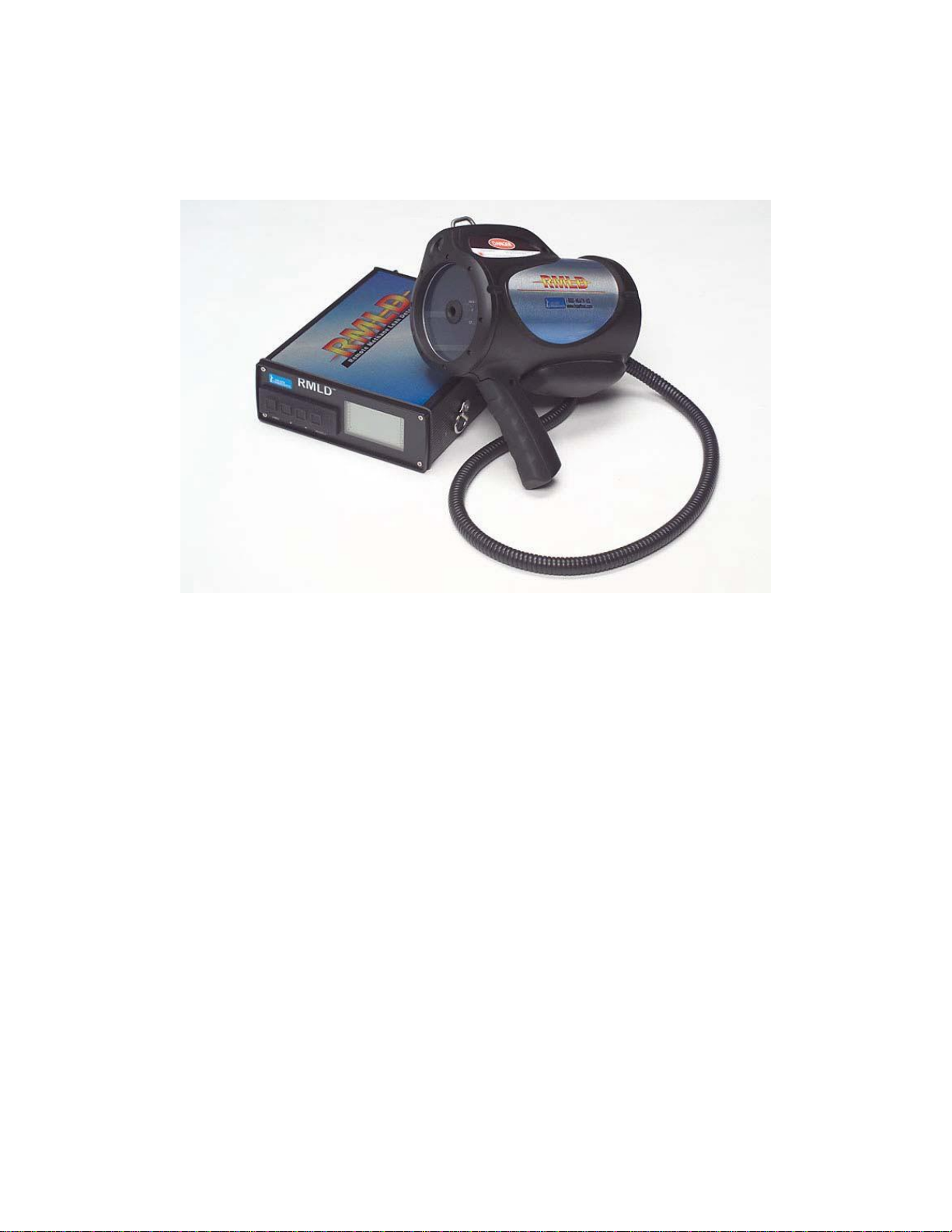
The HEATH Remote Methane Leak Detector (RMLD™) is a highly advanced
technology, capable of detecting methane leaks from a remote distance. The RMLD is
the firstof a new generation of leak survey instruments that will greatly improve the
productivityand safety of leak survey.
With the RMLD it is now possible to survey areas that are hard to reach or not easily
accessible. The RMLD does not have to be within the gas plume because it uses laser
technology known as Tunable Diode Laser Absorption Spectroscopy. As the laser passes
through a gas plume, the methane absorbs a portion of the light, which the RMLD then
detects. This technology makes it possible to detect leaks along the sight line without
always having to walk the full length of the service line.
Fig.
1-2
Using laser technology, remote detection allows you to safely survey areas that may be
difficult to reach such as busy roadways, yards with large dogs, fenced off areas, and
other hard to access places.
It is designed to be selective to detecting methane only, and will not false alarm on other
hydrocarbon gases. Gas concentration is calculated by the amount of Infrared light
absorbed by the gas. Since gas is detected along the line of sight of the laser, the
concentration is reported as Parts-per-Million-Meter(ppm-m). Thus, the RMLD
measures the gas cloud concentration times the width of the gas cloud. Based on the
local meteorological conditions, a given amount of gas escaping from the ground will
produce a plume that varies in size and uniformity of concentration levels. The
plume,
by
nature, is variable and dependent on the soil conditions, temperature, wind, and leak
rate.
Page 7 of 36
101515-0RMLDMANUALREV F
The RMLD consists of two main interactive components:
•
Transceiver
•
Control Module
Fig 1-3: The RMLD system consists of a Laser Emitter/Receiverand a Control
Module
The Transceiver has two lasers. The Infrared laser is non visible and is continuously on
while the unit is turned on. The operator turns on the visible green Spotter laser by
depressing the trigger button.
The RMLD operates under a variety of environmentalconditions including cold or hot
weather and light rain. Its rugged design will stand up to normal field use and operating
conditions. Its sensitivity or range is not affected by reasonable amounts of dust on the
optics window.
The RMLD has built-in Self-test and Calibration functions that will assure that the
instrument is operating properly. Using the calibration cell built into the carrying case,
the operator can perform the self-test and calibration as part of a daily start up routine.
While in operation, the RMLD continuouslymonitors several parameters to ensure that
the instrument is functioning properly. Should any of these parameters go outside of the
operational limits, an audible alarm will sound and a Fault/Warning error message will be
displayed on the display.
A training video is provided with the instrument. It is highly recommended that the user
view the video to learn basic techniques on surveying with the RMLD.

Page 8 of 36
101515-0RMLDMANUALREV F
Chapter I
RMLD System Specifications
Detection Method:
Tunable Diode Laser Absorption Spectroscopy (TDLAS)
Measurement Range:
0 to 99,999 ppm-m
Sensitivity:
5 ppm-m at distance from 0 to 50 ft (15 m)
10 ppm-m or better from 50 to 100 ft (15 to 30 m)
Detection Distance:
100 ft (30 m) nominal. Actual distance may vary due to
background type and conditions
Beam Size:
Conical in shape with a 22”width at 100 ft. (56 cm at 30 m)
Detection Alarms Modes
Digital Methane Detection (DMD):
Audible tone relative to concentration when
detection threshold exceeded.
Adjustable Alarm Detection Threshold from 0 to
255 ppm-m
Pure Tone:
Continuous audio tone relative to concentration
System Fault Warning
Audible tone and indication on the display
Self Test & Calibration
Built-in Self-Test and Calibration function verifies
operation and adjusts laser wavelength for maximum
sensitivity. Test gas cell integrated with carrying case.
Compliance:
EMC (EN61000-6-2, EN6100-6-4) Pending
Laser Eye Safety:
(CDRH, ANSI and IEC)
IR Detector Laser:
Class
I
Green Spotter Laser:
Class IIIa; Do not stare into beam or view directly
with optical instruments.
Display:
Large easy to read backlit LCD (.75”Numeric)
Operating Temperature
0° to 122° F (-17° to 50° C)
Humidity
5 to 95 % RH, non-condensing
Enclosure:
IP54 (Water splash and Dust resistant)
Instrument Weight:
9 lbs (Transceiver 3 lbs, Controller 6 lbs) (4 kg; 1.3 kg,
2.7 kg)
Carry Case:
14 lbs; 34”x 9 ½”x 14”(6.4 kg; 86 cm x 24 cm x 36 cm)
Power Supply
Internal rechargeable Li-ion battery
External Backup Battery pack with 5 C cells (Optional)
Battery Operating Life
8 hours at 32° F without backlight on (Internal battery)
Battery Charger
External, in-line, 110 –240 VAC, 50 / 60 hertz universal
type with charge indicator (8 hours maximum to full charge)
Shoulder Strap
Single over the shoulder padded strap
Ergonomic dual strap and belt system (Optional)

Page 9 of 36
101515-0RMLDMANUALREV F
RMLD System Components
This Chapter describes the features of the RMLD. Please refer to Figure 1-4 for
illustrations of individual parts.
Calibration
Cell
Carrying
Case
Shoulder
Strap
Manual&
Training Video
External
PowerSupply
(optional)
Earphone RMLD
Battery
Charger Charger
Adaptors
Fig. 1-4: System Components.
Controller
The controller provides the user interface display, menu selection buttons, and external
connections such as RS-232, battery charger port, external power supply port, headphone
port, and on/off button.

Page 10 of 36
101515-0RMLDMANUALREV F
Transceiver
The transceiver provides the laser launch for the infrared detection beam, visible green
spotter laser, and spotter laser button. Harness hooks are provided to allow the unit to be
suspended from the harness.
Carrying Strap
The RMLD is provided with a single carrying strap with shoulder pad. An optional dual
strap harness is also available.
Battery Charger
The battery charger is provided to recharge the instrument after use. The charger is a
universal 110 - 240 VAC, 50 / 60 hertz with charger indicator. Adaptors are provided to
convert the style plug for different types of receptacles.
Instruction CD
The Instruction CD contains the following items:
1. Instruction Manual that provides instructions on the uses and operation of the
instrument.
2. Training Video that illustrates proper use and techniques to fully utilize the
instrument.
3. Additional HEATH product information.
4. HEATH contact information.
Carrying Case
The carrying case provides protection for the instrument during storage or transportation.
The instrument should be kept in the case while not in use. Integrated into the carrying
case is a calibration gas cell.
Headphone
Allows the operator to listen to the audible tones through a headphone instead of the
external speaker.

Page 11 of 36
101515-0RMLDMANUALREV F
Optional Accessories
Dual Shoulder Strap Harness
The dual shoulder strap harness provides extra comfort and support for carrying the
instrument for an extended time. The built-in lanyard is used to carry the weight of the
transceiver and provide additional stability and control of the unit while surveying.
HEATH strongly suggests that this harness be used by personnel who use the instrument
on a continuous basis to limit fatigue when holding the transceiver and to improve
surveying technique.
Fig
1-5
External Power Supply
The external power supply is a back-up battery provided to extend the operating time of
the instrument if the internal battery is not charged enough to run the instrument. This
power supply contains 5 “C”batteries.
Fig
1-6
Page 12 of 36
101515-0RMLDMANUALREV F
Chapter II
Battery Charging
Rechargeable Battery
The RMLD has an internal, rechargeable Li-ion battery that provides the main power to
the instrument. This battery is designed to provide 8 hours of operating time when fully
charged. The battery must be recharged between use to assure no interruption in
use.
The
display features a battery life remaining indicator. Accuracy of this indicator is
within 20% of the actual capacity. This indicator should be used only as a reference.
Always start the day with a full charge to ensure a full day’s use.
To maintain the best accuracy of the battery indicator, periodically deep discharge the
battery and then fully charge the battery without any interruption. To deep discharge the
battery, allow the instrument to run until it shuts itself off. This should also be needed if
the indicator does not follow the actual charge, e.g., if the instrument stops operating
while the battery indicator is reading that a charge remains or if the indicator is flashing
Fig.
2-1
Battery charge
indicator
**Note**
To obtain full battery capacity, charge the battery when the ambient temperature is
above
50º F (10º C).
**Caution**
To prevent damage to the battery or electrical circuits, always plug the charger into a
surge-protected outlet.
**Note**
The prolonged un-use of battery inside or outside the instrument can lead to battery chemistry
being irreversibly damaged leading to permanent failure of the battery. It is recommended to have
the battery go through at least one (1) charge-discharge cycle once every month if the battery is
not being used for long periods of time.
When storing the instrument or the battery for more than a week, leave the battery charged up to
about 40% and store at room temperature of about 60-70º F.

Page 13 of 36
101515-0RMLDMANUALREV F
Battery Charger
The RMLD is provided with a universal AC battery charger. The plug of the charger can
be changed to fit the type of receptacle used in your location.
Charging Procedure
To recharge the internal battery, perform the following procedure:
1. Turn the instrument off.
2. Plug the AC plug into a surge-protected outlet.
3. Plug the charger plug into the RMLD charger port.
4. A blinking green light indicates that the charger is charging.
5. Allow the unit to charge until the green indicator is on solid.
6. Unplug the charger.
Fig.
2-2
**Warning**
Only use the HEATH supplied RMLD battery charger to recharge the
unit. Use of any other charger may cause severe damage to the battery
or electrical circuits.

Page 14 of 36
101515-0RMLDMANUALREV F
Chapter III
Operating the RMLD
This chapter provides information on the use of the RMLD. It provides an explanation of
working with the menu, setting operational parameters, or enabling functions of the
instrument.
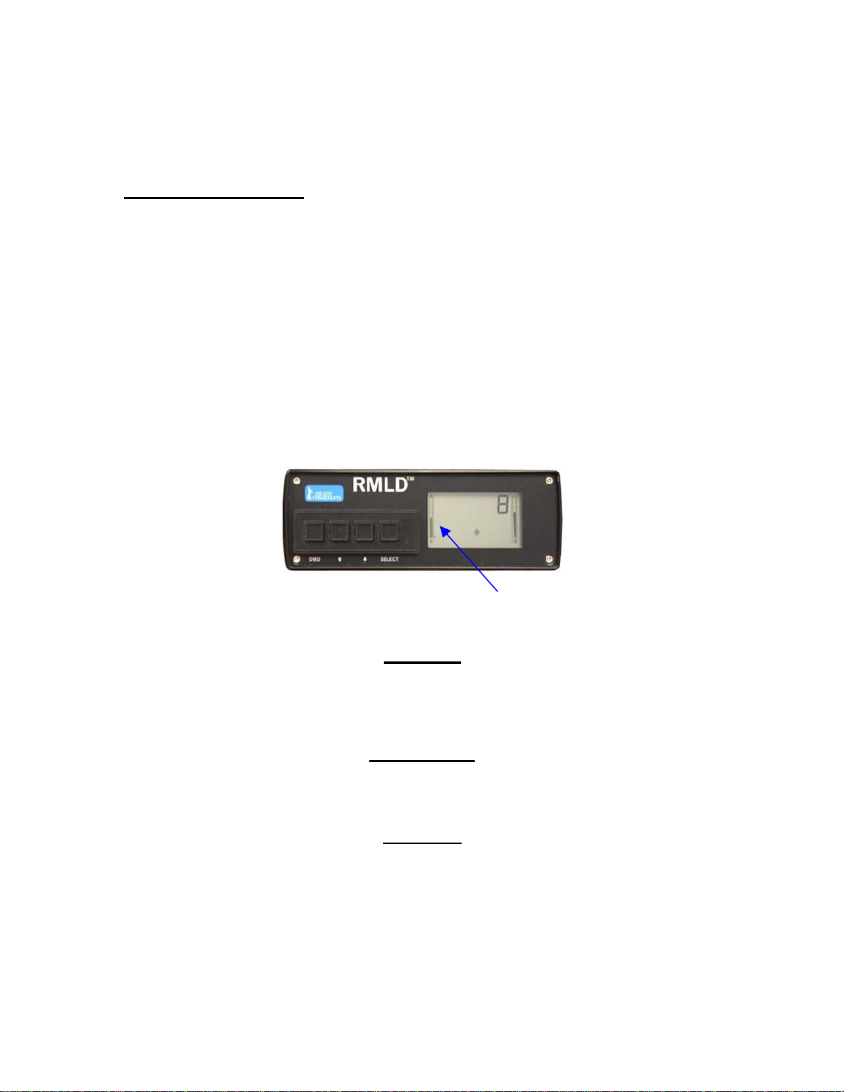
Battery
Indicator
DMD icon Gas
Concentration Volume
Warning
DMD button Error
Backlight
icon
Up Down button Select button Re-Try Self-Test OK Spottericon
Fig.
3-1
Figure 1: RMLD front panel and display. (Note: for illustration,all the display icons are shown.
During actual operation, only the icons associated with an active function will be displayed)
DMD button: press to turn on/off the DMD mode.
Up adjust button: press to increase a value or to acknowledge a user prompt.
Down adjust button: press to decrease a value.
Select button: press to scroll through the menu options.
Display:
Battery Indicator: displays the amount of battery charge.
Gas Concentration:displays the amount of gas in ppm-m. Over range is
indicated by a 1-------.
Volume: displays the volume level of the speaker and headphone
Warning: icon indicating that the instrument is outside of an operation limit.
Error: icon indicating that a fault condition has occurred; the instrument is no
longer functioning properly.
DMD: icon indicating that the DMD detection mode is on.
Spotter: icon indicating that the spotter laser is enabled.
Backlight: icon indicating that the backlight is on.
Re-try: icon indicating that the self-test failed and should be performed again.
Self-Test: icon indicating that the self-test mode is enabled.
OK: icon indicating that the self-test successfully completed.

Page 15 of 36
101515-0RMLDMANUALREV F
Headphone
port Chargerport
RS-232
port
External
Power
port
Fig. 3-2: RMLD rear panel
Headphone port: receptacle for the headphone plug.
Charger port: receptacle for the battery charger plug.
Power Switch: depress the switch to turn the instrument on/off.
Ext. Power: receptacle for the external backup battery plug.
PowerSwitch
RS-232 port: receptacle for a DB-9 connector for interfacing to a PC (Used for
factory calibration purposes only).
Turning the RMLD On
Depress the Power Switch located on the rear panel. When the unit first turns on, the
green Spotter laser will briefly flash, and the display will shortly show all of the
icons.
The
display will then return to its run display mode showing the ppm-m reading. The
Warning icon will also shortly display as the laser starts up. This warning should turn off
after a few seconds. The instrument will turn on with the same settings (e.g., Alarm
Detection Threshold, Spotter On, etc.) as when it was turned off.
**Note**
The Infrared detection laser is continuously on and the instrument is measuring the
methane concentration while the instrument is on.

Page 16 of 36
101515-0RMLDMANUALREV F
Turning On the Spotter Laser
**Caution**
The green spotter laser in under the control of the operator and is on only when the
spotter trigger switch is depressed. While using the green spotter laser, be courteous to
others by not shining it towards their eyes or causing vehicle drivers to be distracted.
This type of laser is commonlysold in retail stores and used for business presentations. It
is safe as long as the operator properlyuses it.
**Danger**
The visible green spotter laser is a Class IIIa laser product. Do not stare
into beam or view directly with optical instruments.
Spotter laser
IR Detector
laser
Spottertrigger
switch
Fig.
3-3
Turning the RMLD Off
Depress the power switch located on the rear panel. The instrument will power off. The
settings (e.g., Alarm Detection Threshold, Spotter On, etc.) will be automatically saved.
Using the Menu
The RMLD menu allows the operator to adjust certain operational values or to turn on/off
other functions. The operator can change the following operational values:
1. Volume.
2. Alarm Detection Threshold.
The following functions can be turned on/off or enabled:
1. Self-Test.
2. Spotter.
3. Backlight.

Page 17 of 36
101515-0RMLDMANUALREV F
By pressing the Select button, the Menu options are scrolled through in the following
order:
•
Self-Test
i. Press Up button to initiate the Self-Test and Calibration
1. Press the Up button to acknowledge user prompts (OK or
Retry).
Ready to
start
Self-Test
•
VOL
i. Press Up button to increase the volume level.
ii.Press Down button to decrease the volume level.
•
SPOi. Press Up button to enable or disable the Spotter laser.
•
AL i. Press Up button to increase the Alarm Detection Threshold.
ii.Press Down button to decrease the Alarm Detection Threshold.
Fig. 3-4

Page 18 of 36
101515-0RMLDMANUALREV F
•
BACLI
i. Press Up button to turn on or to turn off the display backlight.
Fig.
3-5
Although the ppm-m readout will not be updating, the instrument will still operate
properly while in a menu option other than the run display.
Using the DMD Mode
The Digital Methane Detection (DMD) mode is a highly sophisticated detection algorithm
that greatly enhances the use of the RMLD. In most situations, the operator should survey
with the DMD mode turned on. To turn on the DMD mode, press the DMD button (the
DMD icon will appear on the display). This mode can only be activated while in the main
survey screen.
DMD icon is on
Fig. 3-6: DMD icon is displayed when in DMD
mode.
While using the DMD, no sound will be heard until a detection of methane occurs. The
pitch of the sound will be relative to the methane concentration. The higher the pitch, the
stronger the methane concentration is.
A low-pulsating or continuous sound will indicate a warning due to an infrared laser low
light level condition or instrument fault. The warning icon will also be displayed
indicating that the light level is too low (See Long Range Scanning Pg. 23). The operator
needs to move in closer to get in range.
Should the warning persist, it could be due to a fault in the instrument. Check the error
code being displayed and follow the instructions in the troubleshooting guideline.
The DMD will indicate detection when the ppm-m exceeds the average background plus
Alarm Detection Threshold level, or when the reading is excessive. While the low light

Page 19 of 36
101515-0RMLDMANUALREV F
warning is sounding, the RMLD may still be able to detect very large gas concentrations,
indicated by a high pitch tone.
The Alarm Detection Threshold controls the sensitivity of the DMD. The operator can
adjust the Alarm Detection Threshold. Your company’s survey procedure may
require
the
use of a specific value or procedure to set it. Set the Alarm Detection Threshold such
that the false detection rate is low, while not too high that leaks are missed.
To change the Alarm Detection Threshold, scroll through the Menu options until the
“AL”option is displayed. Press the Up or Down button to increase or decrease the
threshold. The higher the threshold setting is, the less sensitive the instrument becomes.
Using the Pure Tone Mode
The Pure Tone mode of the RMLD plays a continuous tone that is relative to the
instantaneous concentration level. The higher the pitch of the tone, the higher the
methane concentration level. No sound at all will indicate a low light level condition or
instrument fault. Note that the pitch level increases as you scan at a further distance.
This is due to the ambient amount of methane in the air.
Tone level is
proportional
to
ppm-mreading
Fig.
3-7
DMD icon is off
The pure tone mode is most effective when used up close to help verify low level
detections or to help isolate the highest gas concentration.
To verify a low level leak the following procedure should be used:
1. Stand back about 10 ft. from the leak with the wind to your back if possible.
2. Sweep the laser back and forth across the leak while maintaining a constant
distance.
3. Listen for a consistent increase in tone level as the beam sweeps through the leak.
Very small leaks will have just a slight increase in tone.
To isolate the spot with the highest concentration, the following procedure should be
used:
1. Stand back about 10 ft. from the leak with the wind to your back if possible.
2. Sweep the laser starting from the up-wind side, in and around the leak area.
3. Listen for the highest tone level.
4. Change your angle slightly and re-scan the leak zone.

Page 20 of 36
101515-0RMLDMANUALREV F
5. If the location with the highest pitch is consistent then the location of the leak is at
that spot.
6. If the pitches are not consistent then keep working the area. The gas plume may
be drifting around causing inconsistent readings. In some cases, the gas plume
may be large enough that localization is not very accurate.
Self-Test and Calibration
The RMLD has a built-in function to perform a Self-Test and Calibration of the laser
wavelength. The self-test feature should be used on a daily basis to ensure that the
instrument is in proper working order. HEATH recommends that the self-test function
be performed prior to the beginning of your survey day. Each Self-Test & Calibration
should be recorded into a daily log. An example daily log has been included at the end of
this manual for your convenience.
To perform the Self-Test and Calibration, the following procedure should be performed:
1. Remove the controller from the carrying case.
2. Turn on the instrument and allow it to warm up for 2 to 3 minutes.
3. Place the transceiver in its position in the carrying case; making sure it is all the
way in place and flat.
4. Press the SELECT button until the SELF-TEST icon is shown on the display
(Note: the Retry and OK icon are also displayed).
Fig.
3-7
5. Press the UP button to initiate the self-test. The number 255 will then be
displayed.
6. When the OK icon is displayed, the instrument passed the self-test.
a. If the RETRY icon is displayed then the instrument failed the self-test.
This manual suits for next models
1
Table of contents
Other Heath Consultants Gas Detector manuals


Popular Gas Detector manuals by other brands


Tecnocontrol
Tecnocontrol SE138K user manual

Emerson
Emerson Rosemount 625IR manual

Honeywell
Honeywell BW Technologies GasAlertQuattro 1 user manual

Tecnosystemi
Tecnosystemi FIDO BAU user manual

S+S Regeltechnik
S+S Regeltechnik AERASGARD RCO2-A NT operating instructions

Consilium
Consilium Salwico ST400 H2S Calibration instructions

Bosean Electronic Technology
Bosean Electronic Technology K-600 user manual

BEINAT
BEINAT SGM595-H2CH Installation and user guide

Atex
Atex DGTt2-ex installation manual

RKI Instruments
RKI Instruments GX-2009 Operator's manual

Seitron
Seitron RYM02M Series User Manual and Safety Instructions

Evikon
Evikon E2610-CO user manual