manuals.online logo
Brands
  1. Home
  2. •
  3. Brands
  4. •
  5. Evikon
  6. •
  7. Gas Detector
  8. •
  9. Evikon E2610-CO User manual

Evikon E2610-CO User manual

E2610 series gas detectors are compact and easy-to-use instruments.
The devices utilise novel fully calibrated and temperature compensated gas
sensors with excellent repeatability, stability and long lifetime.
Two relays with switch-over contact may be used for remote signalling or
ventilation control. Flashing LED and an internal buzzer give alarms at two set-
points.
Safety requirements
Always adhere to the safety provisions applicable in the country of use. Do not
perform any maintenance operation with the power on. Do not let water or foreign
objects inside the device.
Operating conditions
The device should be used in explosion-safe (non ATEX -rated) indoor areas at
the atmospheric pressure ±10% and 15...90 %RH without condensation
Avoid exposure to highly corrosive gases (H2S, SO2, HCl, Cl2 etc), or high
concentrations of basic gases, such as ammonia
Avoid mechanical shock or strong vibrations.
Avoid sources of electromagnetic interference
See Specifications table for more details
Installation
There are no precise rules or standards to follow when installing the gas detectors.
The following points must be taken into account:
application (air quality control or leakage detection),
properties of the space under investigation (room geometry, direction and velocity of
air flows etc),
detected gas (relative density to air, whether the gas is flammable, or toxiс, or
oxygen displacing, whether the gas is heated),
safety: strong vibrations, mechanical shock, and the sources of strong
electromagnetic interference should be avoided,
the device should be accessible for maintenance and repair.
For early leakage detection install the sensor as close as possible to the potential
leakage sources (flanges, valves, pressure reducers, pumps, etc), taking into
consideration other points listed above. Do not locate the detector close to
ventilation openings and strong air currents. Avoid the areas without air circulation
(corners, niches) as well. For general area monitoring without definite leakage
sources, the detectors should be distributed evenly in the room. For personal
safety control the detectors are installed in the breathing zone (at the height of the
head of people or animals). Recommended sensor position is vertical, pointing
downwards. See Installation guidelines section for more information.
The gas detector should be mounted on a wall at a place located in proximity to
possible gas source. Since carbon monoxide has practically the same density as
air, the detector should be installed in the breathing zone (1.5 m above the floor,
the height may vary depending on application) or near the potential leakage
source. Do not locate the detector close to ventilation openings and strong air
currents. Avoid the areas without air circulation (corners, niches) as well. The
device should be available for maintenance and repair.
Connections
1. Detach the base of the enclosure by gently pulling along four guiding pins.
2. Attach the base to the wall with two screws. (see drawings below).
8537
85
63
3. Use rounded cutouts on the side of the base to let in the cables from the power
supply and of the external devices as shown below.
For easier connection, terminal blocks of E2610 series devices are removable. To
dismount the terminal block, pull it off from the PCB.
Connect the power terminals N and L to the 24 V AC/DC source if you are using
detector version -24 or to 230 VAC mains if you are using detector version -230
(see diagram below).
The terminals on the E2610 series devices are suitable for a wide range of wires
with cross-section 0,2...1,5 mm2. We recommend to strip the wire end by 5...6 mm
and tin it, or to use the wire end sleeves. To connect wire, loosen the screw, insert
the wire end into terminal hole and tighten the screw.
RE1 RE2
N L
PSU
RE1
RE2
sensor*
x5
buzzer
*Sensors may have different shape and/or size
Connect external devices. Relay switch-over outputs may be used to control
directly 24 V or 230 V (for versions -24 and -230 respectively) powered alarm
sirens, ventilation fans, shut-off valves or other actuators.
Attach terminal blocks to the board
4. Push enclosure to the base.
5. Turn on the power. It will take ca. 60 seconds after switching on for the sensor
to stabilize.
Operation
During the first ca.60 seconds after powering on E2610 performs a warming-up
and self-diagnostic routine, indicated by the flashing of each LED. The upper dual-
color LED remains continuously green in normal operation and blinks red in case
of device or sensor fault. The warm-up time depends on the sensor type,
unpowered period and atmosphere.
During the first 30 seconds after powering on you may select automatic or manual
mode of alarm release. By shortly (< 2 s) pressing the button on the device’s front
panel you enable the automatic mode, by pressing the button for 2...10 s —
manual mode. The activation of the automatic mode is followed by a single LED
blinking and acoustic signal. If manual mode is activated, double acoustic and light
signal follows.
If gas concentration exceeds the LOW alarm setpoint, the bottom red LED starts
flashing at a rate of 1 Hz, and the relay RE1 switches over. The first alarm stops
automatically if the gas concentration drops below 80% of the LOW alarm
setpoint.
If gas level exceeds the HIGH alarm setpoint, the bottom red LED starts flashing
and the buzzer starts beeping at a rate of 2 Hz, and also the relay RE2 switches
over. Depending on the selected release mode, the HIGH alarm stops
automatically or can be stopped by pressing the button, on condition that the gas
level has dropped below 80% of the LOW alarm setpoint.
Beyond the warm-up period, holding down the button for 2...10 seconds and
releasing causes E2610 to reset and perform the self-diagnostic routine for testing
purposes.
When holding the button down for over 10 seconds, E2610 imitates the reaching
of the HIGH setpoint with the respective light and sound indication and switching
over the relays.
Warranty
This product is warranted to be free from defects in material and workmanship for
a period of one year from the date of original sale. During this warranty period
Manufacturer will, at its option, either repair or replace product that proves to be
defective. This warranty is void if the product has been operated in conditions
outside ranges specified by Manufacturer or damaged by customer error or
negligence or if there has been an unauthorized modification.
Carbon monoxide
Colourless, odourless, and tasteless gas. Highly toxic.
Synonyms: Carbonous oxide, Carbon(II) oxide, Flue gas, Monoxide
Carbon monoxide is formed as a result of incom lete combustion of carbon-
containing com ounds, e.g. while o erating a furnace, an oven or an engine when
there is a limited su ly of air.
Chemical formula CO
Molar weight 28
Relative gas density (to air) 0.97
Conversion 1 m = 1.15 mg/m3
Boiling oint −191.5 °C
Low ex losive limit (LEL), % vol in air 12.5
U er ex losive limit (UEL), % vol in air 74
Odour Odourless
Hazards Highly toxic. Mild oisoning causes
lightheadedness, confusion,
headache, dizziness, and flu-like
effects. Larger ex osures can lead
to toxicity of the CNS and heart,
and death. After acute oisoning,
long-term roblems may occur. CO
also have negative effects on a
baby if ex osed during regnancy.
Chronic ex osure to low levels can
lead to de ression, confusion, and
memory loss.
Ex osure limits
(NIOSH)
TWA 40 mg/m3 /35 m
IDLH 1380 mg/m3 /1200 m
Conversion of m to mg/m3 is calculated for 25°C and 1 atm.
Installation guidelines
(See Installation section for general information.)
Carbon monoxide has ractically the same density as air and s reads evenly in the
room. Install the sensor in a roximity to ossible leakage or generation source, taking
into consideration the tem erature of the gas, the air currents in the room etc
Calibration
E2610-CO detectors have been calibrated by Manufacturer with standard gas
mixtures before delivery. Provided that the sensor is used under moderate
conditions, field recalibration is recommended every 6 months. Please contact your
dealer for more information
Maintenance
Do not erform any maintenance o eration with the ower on.
Clean the device with soft dam cloth. Do not use any abrasive cleaning agents. Do
not immerse the device into water or any cleaning media.
Delivery set
–Carbon Monoxide Detector E2610-CO
– Mounting accessories: 2 screws and 2 lastic dowel lugs
E2610-CO_UM_EN Rev 19.11.2019
Specifications
Detected gas Carbon monoxide
Sensor ty e Electrochemical cell
Sam ling method Diffusion
Detection range 0...200 m 0...1000 m
Alarm set oints
(release-LOW-HIGH) 18 - 25 - 125 m 88 - 125 - 250 m
Resolution/digital unit 1 m
Accuracy ±(3% of range + 5 m CO)
Res onse time ~ 30 seconds
Sensor lifetime > 6 years
Calibration interval 6 months
O erating conditions
-20...+50°C, 15...95% RH without condensation,
ressure 0,9...1,1 atm
non ATErated areas
Avoid strong mechanical shock, vibrations or EMI
Avoid ex osure to corrosive gases
NOTE The sensor may exhibit sensitivity to acetylene,
etylene, hydrogen and nitric oxide
Warm-u time u to 1 minute, de ending on un owered eriod and
atmos here
Power su ly 11...30 V DC/AC (version -24)
or 90...265 VAC (version -230)
Power consum tion < 2 VA
Digital interface UART
Relay out uts 2 × SPDT, max 5 A, 30 VDC / 250 VAC
Alarm Buzzer 85 dB
Enclosure ABS lastic with ventilation slots, wall-mount,
rotection class IP20
Dimensions 85 × 85 × 37 mm
Electromagnetic
com atibility according to 2014/30/EU, 2014/35/EU and EN61321-1
standard requirements
Evikon MCI OÜ Teadus argi 7, Tartu inf[email protected]
Tel +372 733 6310 50411 Estonia www.evikon.eu
Carbon Monoxide Detector
E2 10-CO
User manual

Other manuals for E2610-CO

1

Other Evikon Gas Detector manuals

Evikon E2658-CO User manual

Evikon

Evikon E2658-CO User manual

Evikon E2610-LEL User manual

Evikon

Evikon E2610-LEL User manual

Evikon PluraSens E2608 Series User manual

Evikon

Evikon PluraSens E2608 Series User manual

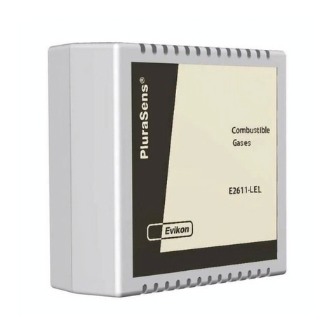
Evikon E2611-LEL User manual

Evikon

Evikon E2611-LEL User manual

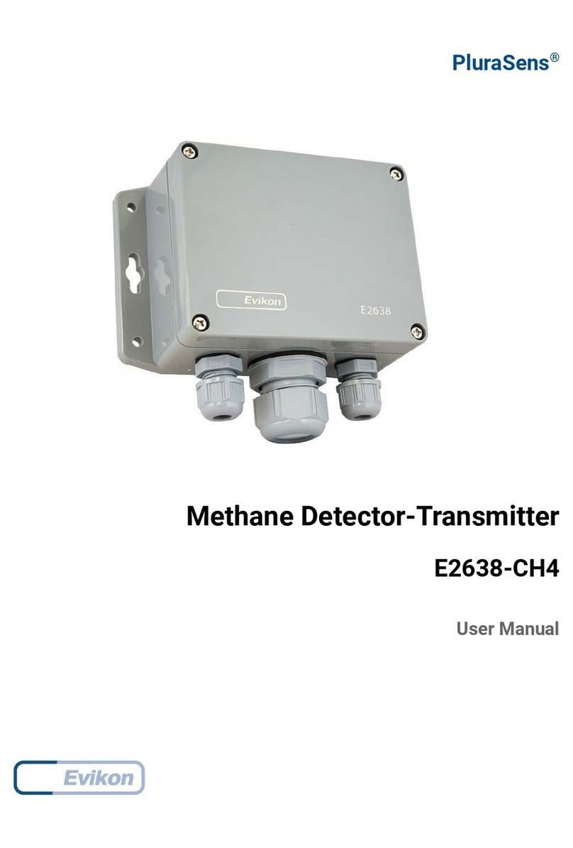
Evikon PluraSens E2638-CH4 User manual

Evikon

Evikon PluraSens E2638-CH4 User manual

Evikon PluraSens E2608-LEL User manual

Evikon

Evikon PluraSens E2608-LEL User manual

Evikon PluraSens E2608 Series User manual

Evikon

Evikon PluraSens E2608 Series User manual

Evikon E2608-CH4 User manual

Evikon

Evikon E2608-CH4 User manual

Evikon E2658-CO User manual

Evikon

Evikon E2658-CO User manual

Evikon E2632 User manual

Evikon

Evikon E2632 User manual

Evikon PluraSens E2638-NO User manual

Evikon

Evikon PluraSens E2638-NO User manual

Evikon PluraSens E2618-NH3-E User manual

Evikon

Evikon PluraSens E2618-NH3-E User manual

Evikon PluraSens E2658-LEL User manual

Evikon

Evikon PluraSens E2658-LEL User manual

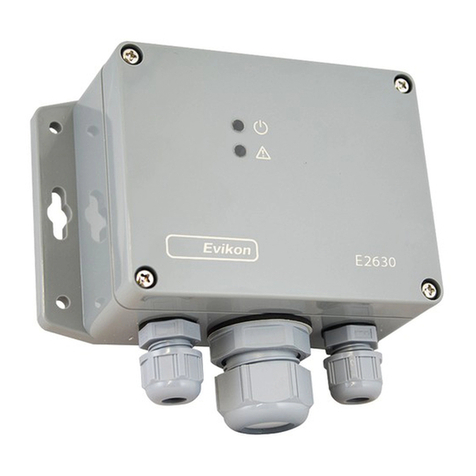
Evikon E2630 Series User manual

Evikon

Evikon E2630 Series User manual

Evikon PluraSens E2608 Series User manual

Evikon

Evikon PluraSens E2608 Series User manual

Evikon PluraSens E2608 Series User manual

Evikon

Evikon PluraSens E2608 Series User manual

Evikon PluraSens E2658 Series User manual

Evikon

Evikon PluraSens E2658 Series User manual

Evikon PluraSens E2658-C2H4 User manual

Evikon

Evikon PluraSens E2658-C2H4 User manual

Evikon E2648 Series User manual

Evikon

Evikon E2648 Series User manual

Evikon PluraSens E2608 Series User manual

Evikon

Evikon PluraSens E2608 Series User manual

Evikon E2610-CO User manual

Evikon

Evikon E2610-CO User manual

Evikon E2630 Series User manual

Evikon

Evikon E2630 Series User manual

Evikon E2630-LEL User manual

Evikon

Evikon E2630-LEL User manual

Evikon PluraSens E2638 Series User manual

Evikon

Evikon PluraSens E2638 Series User manual

Popular Gas Detector manuals by other brands

WatchGas UNI Sustainable quick start guide

WatchGas

WatchGas UNI Sustainable quick start guide

CHANCE C4030979 operating instructions

CHANCE

CHANCE C4030979 operating instructions

3M 110XL Series User instructions

3M

3M 110XL Series User instructions

RS PRO RS GD-38 instruction manual

RS PRO

RS PRO RS GD-38 instruction manual

Tecnocontrol TS282K Series user manual

Tecnocontrol

Tecnocontrol TS282K Series user manual

Tecnocontrol SE138PM user manual

Tecnocontrol

Tecnocontrol SE138PM user manual

Tecnocontrol SE126K user manual

Tecnocontrol

Tecnocontrol SE126K user manual

Tecnocontrol SE148K quick start guide

Tecnocontrol

Tecnocontrol SE148K quick start guide

Tecnocontrol TS293IM user manual

Tecnocontrol

Tecnocontrol TS293IM user manual

GASTRON G-Finder GFS-100 Series instruction manual

GASTRON

GASTRON G-Finder GFS-100 Series instruction manual

MSA DF-8500 user manual

MSA

MSA DF-8500 user manual

Emerson Rosemount 928 quick start guide

Emerson

Emerson Rosemount 928 quick start guide

Inficon IRwin S quick start guide

Inficon

Inficon IRwin S quick start guide

Domino GAS HOME Installation and operation manual

Domino

Domino GAS HOME Installation and operation manual

Triplett GSM100 user manual

Triplett

Triplett GSM100 user manual

Techno Control SE148K user manual

Techno Control

Techno Control SE148K user manual

RKI Instruments T3A Operator's manual

RKI Instruments

RKI Instruments T3A Operator's manual

Teknim TFD-1170 installation manual

Teknim

Teknim TFD-1170 installation manual

manuals.online logo
manuals.online logoBrands
  • About & Mission
  • Contact us
  • Privacy Policy
  • Terms and Conditions

Copyright 2025 Manuals.Online. All Rights Reserved.