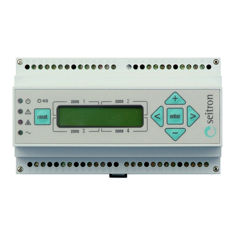
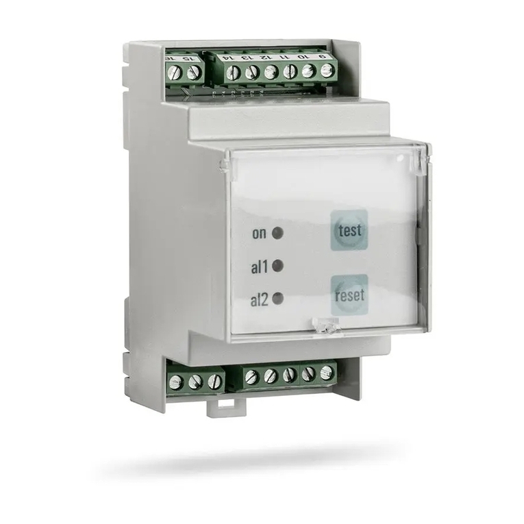
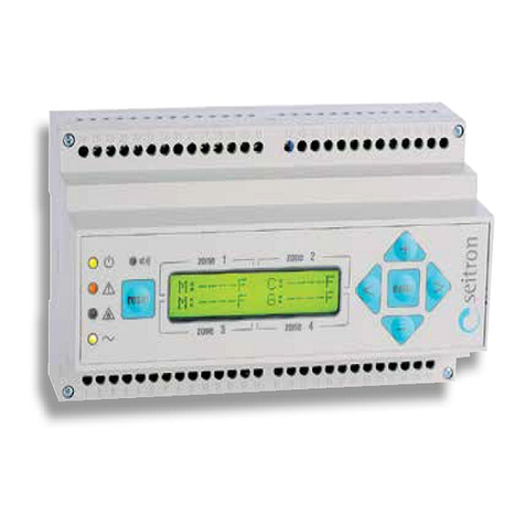
Seitron RYM02M Series Operator's manual

RYM02M0000SE 034674 220520 1
- ITALIANO -
ATEX - DOCUMENTO CORRELATO - COPIA CONFORME ALL’ORIGINALE - QUALUNQUE MODIFICA AL PRESENTE DOCUMENTO RICHIEDE L’AUTORIZZAZIONE DEL RESPONSABILE AZIENDALE PER LA DOCUMENTAZIONE ATEX (RT).
ATEX - LINKED DOCUMENT - COPY COMPLIANT WITH ORIGINAL - ANY CHANGE TO THIS DOCUMENT REQUIRES PRIOR APPROVAL FROM THE RESPONSIBLE FOR ATEX DOCUMENTATION (RT).
In questo stato la centralina supervisiona l’impianto e i ispositivi
collegati.
Visu lizz zioni
Not : Nel seguito, la efinizione i Zona o i Trasmettitore sono
sinonimi, in quanto la zona è legata al relativo trasmettitore.
╔════════════════╗
║S1 CH4 0.1LEL ║ Zona non in allarme
║Select with: <>║
╚════════════════╝
╔════════════════╗
║S1 CH4 none ║ Zona non attivata
║Select with: <>║
╚════════════════╝
Se invece viene rilevata una con izione anomala o i allarme, su
una o più zone, verrà visualizzata alternativamente la schermata
con le concentrazioni / anomalie rilevate e la schermata con la
mappa ei trasmettitori elle zone:
╔════════════════╗ ╔════════════════╗
║S4 CH4 15.1LEL ║ ║ - - - □ - ║
║Select with: <>║ <> ║ 1 2 3 4 5 ║
╚════════════════╝ ╚════════════════╝
Dove nella schermata ella concentrazione, l’ultima lettera a estra
in ica l’anomalia rilevata:
' ': Stato attivo (misura, normale funzionamento).
'E': 'E'n of life (fine vita el sensore el trasmettitore collegato).
'F': 'F'ault (guasto) el trasmettitore i gas (Iout=2 mA).
L’attivazione ello stato i guasto attiva il buzzer e il le
giallo acceso con luce fissa.
'L': 'L'oop (circuito aperto o in corto tra i fili el sensore:
Iout=0 mA ).
'P': Stato i 'P'reallarme.
Tale stato viene attivato se un trasmettitore invia un livello
i concentrazione i gas superiore alla soglia i Preallarme
preimpostata. L’attivazione ello stato i Preallarme attiva il
Relè i Preallarme, il buzzer e il le rosso lampeggiante.
'A': Stato i 'A'llarme 1.
Tale stato viene attivato se un trasmettitore invia un livello
i concentrazione i gas superiore alla soglia i Allarme 1
preimpostato. L’attivazione ello stato i Allarme 1 attiva il
Relè i Allarme 1, il buzzer e il le rosso acceso con luce
fissa.
'H': Stato i 'A'llarme 2.
Tale stato viene attivato se un trasmettitore invia un livello
i concentrazione i gas superiore alla soglia i Allarme 2.
L’attivazione ello stato i Allarme 2 attiva il Relè i Allarme 2,
il buzzer e il le rosso acceso con luce fissa.
Mentre, nella schermata mappatura trasmettitori viene visualizzata
la mappa ei trasmettitori collegati alla centralina con l’in icazione
ell’eventuale stato anomalo:
_ = Zona attivata senza anomalie
□ = Zona attivata con presenza i anomalia / allarme
= Zona non attivata (nella schermata non viene mostrato il
numero el trasmettitore).
Premen o i pulsanti < oppure > si blocca momentaneamente la
visualizzazione sulle schermate con le concentrazioni/anomalie, e
è possibile visualizzarne la situazione per tutte le zone.
Se per circa 6 secon i non si preme nessun tasto, allora si ritorna
automaticamente alla visualizzazione alternata elle schermate.
St to di Pre ll rme
Tale stato viene attivato se un trasmettitore gas invia un segnale i
preallarme alla centralina.
L’attivazione ello stato i Prellarme attiva il corrispon ente relè
(ve i paragrafo “Relè i Preallarme”), il buzzer intermittente e il
le rosso “ ” lampeggiante, mentre il isplay visualizzerà la
seguente schermata:
╔════════════════╗
║S1 CH4 15.2LEL ║ La centralina ha rilevato
║14:55 07/07/18║ una condizione di preallarme
╚════════════════╝
Dove:
S1 è il trasmettitore collegato alla centralina all’ingresso S1.
RYM02M-
CENTRALINA RIVELAZIONE GAS A 2 / 4 / 8 ZONE
II (2)G [Ex Gb] II
MANUALE D’USO E
ISTRUZIONI DI SICUREZZA
ATEX
(Par. 30.1 EN60079-0)
─────────────────────────────────────────────────
[ ] GENERALITA’
─────────────────────────────────────────────────
Alimentazione 12..24 V o 100..240 V , 50..60 Hz
Versioni centralina: 2/4/8 ingressi
Gestisce trasmettitori per CO, GPL, Metano (CH
4
) e Vapori i
benzina (n-ottano).
Ampia liberta' i configurazione ei parametri
Memorizzazione elle con izioni ell'ultimo allarme
Display LCD 2 x 16 caratteri retroilluminato
Montaggio su barra DIN 9 mo uli
Conforme alla norma prestazionale EN 60079-29-1: 2016
─────────────────────────────────────────────────
[b] FUNZIONAMENTO
─────────────────────────────────────────────────
Funzion mento
Centralina a microcontrollore in gra o i monitorare la
concentrazione i gas fino a 2, 4 o 8 zone ifferenti (in funzione
ella versione el pro otto): per ciascuna i queste e' possibile
collegare un trasmettitore 4 .. 20 mA per la misura i G.P.L.,
Metano, Vapori i benzina o Monossi o i Carbonio (CO).
Appena alimentata la centralina mostra le seguenti informazioni:
╔════════════════════╗
║FIRMWARE: ║
║VERSION 033837 ║
╚════════════════════╝
ove ' nnnnnn ' e' la versione el firmware installato.
Questi ati rimangono visibili per circa 2 secon i.
Dopo questo tempo comparirà la schermata i riscal amento.
La centralina inizierà la fase i riscal amento ei sensori ella
urata i 60 secon i.
╔════════════════════╗
║ Waiting 60 sec. ║
║ Sensors Warm Up ║
╚════════════════════╝
Terminata la fase i riscal amento ei trasmettitori e nel normale
funzionamento, in assenza i allarmi, comparirà la seguente
schermata principale (esempio):
╔════════════════╗
║S1 CH4 0.0LEL ║ La centralina mostra lo
║Select with: <>║ stato del primo
╚════════════════╝ trasmettitore rilevato
Dove:
S1 CH4 0.1LEL => è l’effettiva concentrazione
del gas rilevato dal
Trasmettitore collegato
all’ingresso S1 della
centralina
In %LEL (nel caso di
trasmettitori G P L , CH4
o Vapori di Benzina o in ppm
(nel caso di trasmettitori
Monossido di Carbonio)
Select with: <> => premendo i tasti < o > si
passa alla visualizzazione
del trasmettitore successivo
I trasmettitori collegabili alla centralina possono essere iversi per
ciascuna zona; i gas rilevabili sono i seguenti:
- G.P.L. (C
4
H
10
): il isplay mostra 'LPG'
- Metano (CH
4
): il isplay mostra 'CH4'
- Vapori i benzina (n-ottano): il isplay mostra 'VAP'
- Monossi o i Carbonio (CO): il isplay mostra 'CO'.
Via del Commercio, 9/11. 36065 Mussolente (VI)
Tel.: 39.0424.567842 - Fax.: 39.0424.567849 - http://www.seitron.it - e-mail: info@seitron.it

RYM02M0000SE 034674 220520 2
- ITALIANO -
ATEX - DOCUMENTO CORRELATO - COPIA CONFORME ALL’ORIGINALE - QUALUNQUE MODIFICA AL PRESENTE DOCUMENTO RICHIEDE L’AUTORIZZAZIONE DEL RESPONSABILE AZIENDALE PER LA DOCUMENTAZIONE ATEX (RT).
ATEX - LINKED DOCUMENT - COPY COMPLIANT WITH ORIGINAL - ANY CHANGE TO THIS DOCUMENT REQUIRES PRIOR APPROVAL FROM THE RESPONSIBLE FOR ATEX DOCUMENTATION (RT).
P in ica il superamento ella soglia i Preallarme.
Or e D t corrente (non si tratta ella ata e ora in cui si è
verificato l’evento anomalo).
St to di All rme g s (All rme 1 e/o All rme 2)
Tale stato viene attivato se un trasmettitore gas invia un segnale i
allarme alla centralina.
L’attivazione ello stato i Allarme attiva il corrispon ente relè (ve i
paragrafo “Relè i allarme 1 e Relè i allarme 2”), il buzzer e il le
rosso “ ” acceso con luce fissa, mentre il isplay visualizzerà la
seguente schermata:
╔════════════════╗
║S1 CH4 25.2LEL A║ La centralina ha rilevato
║14:55 07/07/18║ una condizione di allarme 1
╚════════════════╝
╔════════════════╗
║S1 CH4 30.5LEL H║ La centralina ha rilevato
║14:55 07/07/18║ una condizione di allarme 2
╚════════════════╝
Dove:
S1 è il trasmettitore collegato alla centralina all’ingresso S1.
A in ica il superamento ella soglia i Allarme 1.
H in ica il superamento ella soglia i Allarme 2.
Or e D t corrente (non si tratta ella ata e ora in cui si è
verificato l’evento anomalo).
St to di Fine vit del sensore (End of life)
Tale stato viene attivato se il trasmettitore invia alla centralina il
segnale i fine vita el sensore.
L’attivazione ello stato i fine vita el sensore attiva il buzzer, i le
ver e e giallo “ ” accesi con luce fissa e può attivare il relè
ausiliario, se impostato (ve i paragrafo “Mo e aux1” o “Mo e
aux2”), mentre il isplay visualizzerà la seguente schermata:
╔════════════════╗
║S1 CH4 ---- E║ La centralina ha rilevato
║Select with: <>║ la condizione di fine vita
╚════════════════╝ del sensore
Dove:
S1 è il trasmettitore collegato alla centralina all’ingresso S1.
E in ica lo stato i Fine vita el sensore el trasmettitore.
Or e D t corrente (non si tratta ella ata e ora in cui si è
verificato l’evento anomalo).
St to di Gu sto del sensore
Tale stato viene attivato se viene rilevato un guasto interno al
trasmettitore.
L’attivazione ello stato i guasto può attivare il relè ausiliario, se
impostato (ve i paragrafo “Mo e aux1” o “Mo e aux2”), il buzzer e
il le giallo “ ” acceso con luce fissa, mentre il isplay
visualizzerà la seguente schermata:
╔════════════════╗
║S1 CH4 ---- F║ La centralina ha rilevato
║Select with: <>║ una condizione di guasto nel
╚════════════════╝ trasmettitore
Dove:
S1 è il trasmettitore collegato alla centralina all’ingresso S1.
F in ica lo stato i guasto trasmettitore.
Or e D t corrente (non si tratta ella ata e ora in cui si è
verificato l’evento anomalo).
St to di Gu sto dell centr lin
I guasti legati alle periferiche interne alla centralina vengono
visualizzati sul isplay come segue:
Se si verifica un guasto interno alla centralina, la stessa si porta in
stato i Guasto.
Overr nge
Se compare la scritta ‘OVR’ al posto el valore i concentrazione,
significa che è stato raggiunto il limite superiore el campo i
misura (overrange).
Lo stato ‘OVR’ corrispon e a una corrente i ingresso superiore a
22mA.
Codice Errore Descrizione dell’errore
01
Errore ella memoria E2 interna.
02
Errore ella RTC esterna.
03
Errore ella memoria FLASH interna.
04
Errore ella memoria RAM interna.
05
Errore sequenza i esecuzione el programma.
╔════════════════╗
║S1 CH4 OVR ║ La centralina ha rilevato
║Select with: <>║ una condizione di Overrange
╚════════════════╝
Nel caso in cui si verifichi la con izione i Overrange, la centralina
attivera' anche i relè ausiliari ‘AUX1’ e/o ‘AUX2’ se abilitati tramite i
parametri installatore ‘Mo e aux1’ e/o ‘Mo e aux2’.
Ogni volta che si verifica una situazione i Overrange ('OVR') e
successivamente sia stata risolta, i rele' torneranno al loro normale
stato i funzionamento a secon a i come è stato configurato il
parametro installatore “Relay latch”.
Relè di Pre ll rme
La centralina gestisce gli eventi i preallarme tramite un rele' i
uscita, “PREALARM”, con contatti in scambio (SPDT). Nel caso in
cui venga raggiunta la soglia i preallarme impostata, la centralina
attiva il relativo rele' i uscita, il buzzer e il le rosso lampeggiante
memorizzan o l’evento. Data e ora ell’ultimo evento verranno
mantenuti nella memoria ella centralina.
ATTENZIONE
Se sono cess te le condizioni che h nno c us to l’ ttiv zione
del relè di pre ll rme, esso tornerà l suo norm le st to di
funzion mento second di come è st to configur to il
p r metro inst ll tore “Rel y l tch”.
Relè di All rme 1 e All rme 2
La centralina gestisce gli eventi i allarme attraverso ue rele' i
uscita, “ALARM1” e “ALARM2”, con contatti in scambio (SPDT).
Nel caso in cui venga raggiunta la soglia i allarme 1 e/o allarme 2
impostata, la centralina attivera' il relè i allarme 1 e/o allarme 2, il
buzzer, il le rosso acceso con luce fissa.
Allo stesso tempo la centralina memorizza, nell’or ine, l'evento i
allarme 1 e i allarme 2: ata e ora ell'ultimo evento sono
mantenuti nella memoria ella centralina.
ATTENZIONE
Se sono cess te le condizioni che h nno c us to l’ ttiv zione
dei relè di ll rme, essi torner nno l loro norm le st to di
funzion mento second di come è st to configur to il
p r metro inst ll tore “Rel y l tch”.
Rele' usili ri
La centralina ispone i ue relè ausiliari con contatti in scambio
(SPDT) che possono essere attivati in base agli eventi e ai mo i
i funzionamento impostati all'installatore tramite il relativo menu.
ATTENZIONE
Se sono cess te le condizioni che h nno c us to l’ ttiv zione
del relè usili ri, esso tornerà l suo norm le st to di
funzion mento second di come è st to configur to il
p r metro inst ll tore “Rel y l tch”.
Visu lizz zione dell'ultimo evento di ll rme
La centralina mantiene in memoria la ata e l'ora el solo ultimo
evento anomalo avvenuto in ciascuna zona.
Questa informazione puo' essere letta in ogni momento all'utente
premen o il tasto ' reset ', a partire alla schermata principale, e
premen o poi i tasti '<' o '>' per visualizzare le iverse zone.
Premere 'reset'
╔════════════════╗
║Zone 1: no event║
║--:-- --/--/--║
╚════════════════╝
Premere i tasti “<” o “>” per
scorrere tra gli eventi memorizzati
╔════════════════╗
║Zone 2 : loop ║
║14:55 02/02/19║
╚════════════════╝
T cit zione del buzzer
Dalla schermata principale, premere i tasti “+” o “-” per tacitare le
segnalazioni acustiche causate a un evento anomalo.
Il buzzer verrà riattivato nei seguenti casi:
- Entran o e successivamente uscen o ai parametri installatore,
nel caso in cui l’evento anomalo non sia ancora stato risolto.
- Nel caso in cui si verifichi un nuovo evento anomalo i priorità
superiore al primo.
RYM02M0000SE 034674 220520 3
- ITALIANO -
ATEX - DOCUMENTO CORRELATO - COPIA CONFORME ALL’ORIGINALE - QUALUNQUE MODIFICA AL PRESENTE DOCUMENTO RICHIEDE L’AUTORIZZAZIONE DEL RESPONSABILE AZIENDALE PER LA DOCUMENTAZIONE ATEX (RT).
ATEX - LINKED DOCUMENT - COPY COMPLIANT WITH ORIGINAL - ANY CHANGE TO THIS DOCUMENT REQUIRES PRIOR APPROVAL FROM THE RESPONSIBLE FOR ATEX DOCUMENTATION (RT).
Reset degli ll rmi
Se sono cessate le con izioni che hanno causato l’attivazione elle
segnalazioni acustiche, visive e ei relè, la centralina ritornerà al
suo normale stato i funzionamento o meno, a secon a i come è
stato configurato il mo o i funzionamento ei relè me iante il
parametro installatore ‘Relay latch’.
Se viene richiesto l’intervento umano per ripristinare il normale
funzionamento ell’intero sistema, opo aver risolto la causa che
ha generato lo stato i allarme e/o guasto, è necessario che
l’utente prema intenzionalmente e per 3 secon i il tasto ' reset '.
Resettan o gli allarmi verranno cancellati tutti gli eventi
memorizzati alla centralina.
Al contrario, se NON viene richiesto l’intervento umano per
ripristinare il normale funzionamento ell’intero sistema, opo aver
risolto la causa che ha generato lo stato i allarme e/o guasto la
centralina ritorna automaticamente allo stato i normale
funzionamento.
ATTENZIONE
- Gli eventi rilev ti d ll centr lin possono essere resett ti
nche se questi non sono st ti visu lizz ti medi nte l
pressione breve del t sto “enter”: quindi si consigli di
scorrere tutti gli eventi memorizz ti prim di premere il t sto
“reset”.
Reset utom tico dei relè
L'azione ei rele' i pre-allarme puo' essere 'auto-ripristinante'
nel caso in cui il parametro i 'ritenuta' (in Rel y l tch - L tch
pr l) sia stato impostato su 'N'. Fare riferimento alla relativa
sezione el manuale per i ettagli.
L'azione ei rele' ausiliari puo' essere 'auto-ripristinante' nel caso
in cui il parametro i 'ritenuta' (in Rel y l tch - L tch ux1 /
L tch ux2) sia stato impostato su 'N'. Fare riferimento alla
relativa sezione per i ettagli.
L'azione ei rele' i allarme puo' essere 'auto-ripristinante' nel
caso in cui il parametro i 'ritenuta' (in Rel y l tch - L tch lr1 /
L tch lr2) sia stato impostato su 'N'. Fare riferimento alla
relativa sezione el manuale per i ettagli.
─────────────────────────────────────────────────
[c] MESSAGGI SUL DISPLAY DELLA CENTRALINA
─────────────────────────────────────────────────
Nel seguito sono escritti i messaggi evi enziati sul isplay ella
centralina in iverse con izioni. Si assume che la Zona 1 sia
impostata per Metano e che la concentrazione sia variabile.
─────────────────────────────────────────────────
Mess ggio displ y: ╔════════════════╗
║S1 CH4 none ║
Spieg zione: 'Zona isabilitata'
La zona relativa non e' stata attivata. Si ricor a che opo aver
collegato un trasmettitore a un ingresso e' anche necessario
attivare sulla centralina la relativa zona.
─────────────────────────────────────────────────
Mess ggio displ y: ╔════════════════╗
║S1 CH4 0.0LEL M║
Spieg zione: 'Normale funzionamento'
Questo e' cio' che il isplay mostra urante il normale
funzionamento. In questo caso la concentrazione e' lo 0% L.I.E.
─────────────────────────────────────────────────
Mess ggio displ y: ╔════════════════╗
║Zone 1 : loop ║
Il le giallo è acceso fisso in corrispon enza el simbolo ' ' e il
buzzer emette un suono continuo.
Spieg zione: 'Loop i corrente'
Il cavo che collega il trasmettitore alla centralina e' interrotto
oppure presenta un corto circuito tra ue. Controllare e riparare il
collegamento relativo alla zona in con izione i guasto.
─────────────────────────────────────────────────
Mess ggio displ y: ╔════════════════╗
║S1 CH4 ---- F║
Il le giallo è acceso fisso in corrispon enza el simbolo ' ' e il
buzzer emette un suono continuo.
Spieg zione: 'Guasto sul sensore gas'.
Il sensore gas e' guasto e sta quin i imponen o 2mA sul loop i
corrente. Controllare il trasmettitore guasto e eventualmente
sostituirlo con uno nuovo.
─────────────────────────────────────────────────
Mess ggio displ y: ╔════════════════╗
║S1 CH4 15.2LEL ║
Il le rosso lampeggia in corrispon enza el simbolo ' ' e il
buzzer emette un suono intermitternte.
Spieg zione: 'Preallarme'.
La concentrazione rilevata ha superato la soglia i preallarme nella
zona controllata. In questo esempio e' stato assunto un valore i
soglia el 10% L.I.E. (valore i fabbrica).
─────────────────────────────────────────────────
Mess ggio displ y: ╔════════════════╗
║S1 CH4 25.2LEL A║
Il le rosso si accen e fisso in corrispon enza el simbolo ' ' e il
buzzer emette un suono continuo.
Spieg zione: 'Allarme 1'.
La concentrazione rilevata ha superato la soglia i allarme 1 nella
zona controllata. In questo esempio e' stato assunto un valore i
soglia el 20% L.I.E. (valore i fabbrica).
Il rele' i allarme, il le rosso e il buzzer sono mantenuti attivi fino
a che il tasto i reset non viene premuto.
─────────────────────────────────────────────────
Mess ggio displ y: ╔════════════════╗
║S1 CH4 30.5LEL H║
.
Il le rosso si accen e fisso in corrispon enza el simbolo ' ' e il
buzzer emette un suono continuo.
Spieg zione: 'Allarme 2'.
La concentrazione rilevata ha superato la soglia i allarme 2 nella
zona controllata. In questo esempio e' stato assunto un valore i
soglia el 30% L.I.E. (valore i fabbrica).
Il rele' i allarme, il le rosso e il buzzer sono mantenuti attivi fino
a che il tasto i reset non viene premuto.
─────────────────────────────────────────────────
Mess ggio displ y: ╔════════════════╗
║S1 CH4 OVR ║
Si accen e il le rosso in corrispon enza el simbolo ' ' e il
buzzer emette un suono continuo.
Spieg zione: 'Fuori scala' (over range).
E' stato superato il limite superiore el campo i misura.
Il rele' i allarme, il le rosso, il buzzer e l'in icazione 'OVR' sono
mantenuti attivi fino a che il tasto i reset non viene premuto.
─────────────────────────────────────────────────
Mess ggio displ y: ╔════════════════╗
║MEMORY FAULT: 01║
║CONTACT SERVICE║
╚════════════════╝
Spieg zione: 'Errore memoria' (memory fault).
E' stato rilevato un errore in una memoria interna. Il funzionamento
non e' piu' affi abile.
Contattare l'assistenza per la sostituzione el ispositivo. I co ici
sono riportati nella tabella “Stato i Guasto ella centralina”.
─────────────────────────────────────────────────
[d] PRIORITÀ EVENTI ANOMALI
─────────────────────────────────────────────────
I iversi stati, prece entemente escritti, legati ai vari eventi
avranno il seguente or ine i priorità (1 max. - 8 min.):
STATO PRIORITA’ (1=MAX)
Fault centralina 1
Open Loop 2
Fault trasmettitore 3
Over Range 5
Allarme 2 6
Allarme 1 7
Preallarme 8
Fine vita sensore 4

RYM02M0000SE 034674 220520 4
- ITALIANO -
ATEX - DOCUMENTO CORRELATO - COPIA CONFORME ALL’ORIGINALE - QUALUNQUE MODIFICA AL PRESENTE DOCUMENTO RICHIEDE L’AUTORIZZAZIONE DEL RESPONSABILE AZIENDALE PER LA DOCUMENTAZIONE ATEX (RT).
ATEX - LINKED DOCUMENT - COPY COMPLIANT WITH ORIGINAL - ANY CHANGE TO THIS DOCUMENT REQUIRES PRIOR APPROVAL FROM THE RESPONSIBLE FOR ATEX DOCUMENTATION (RT).
─────────────────────────────────────────────────
[e] IMPOSTAZIONE PARAMETRI INSTALLATORE
─────────────────────────────────────────────────
Dalla schermata principale, che mostra lo stato attuale i tutte le
zone attive, l'utente puo' acce ere a tutti i sottomenu' che
consentono i mo ificare le impostazioni ei parametri isponibili
per il corretto funzionamento el sistema i rilevazione. Al fine i
acce ere alla configurazione ei parametri e' richiesta una
passwor , il cui valore i fabbrica e' impostato a '0000'. La sua
mo ifica e' obbligatoria per evitare interventi a parte i personale
non autorizzato, come richiesto alle norme vigenti.
ATTENZIONE
L modific dei p r metri inst ll tore deve essere effettu t
d person le qu lific to.
Immissione p ssword
ACCENSIONE
╔════════════════╗
║S01 CH4 0.1LEL ║ Schermata principale (esempio)
║Select with: <>║
╚════════════════╝
premere 'enter'
┌────────────────┐
│Enter pwd: 0000│
│rst <> +- ent│
└────────────────┘
inserire la password ‘0000’
Premendo '<' o '>' si selezionano le singole
cifre
Premendo '+' o '-' si imposta il valore per
ciascuna cifra
premere 'enter'
Nota:
Nelle schermate che seguono, premere '<' o '>'
per scorrere tra i sottomenu' mentre premere
'enter' per entrare in modifica del parametro
selezionato
┌────────────────┐
│Zone activation │ Attivazione / disattivazione
│rst <> ent│ delle zone 1 8
└────────────────┘
┌────────────────┐
│Zone gas type │ Seleziona il gas rilevato dai
│rst <> ent│ trasmettitori collegati
└────────────────┘
┌────────────────┐
│Zone full scale │ Impostazione del fondoscala
│rst <> ent│ dei trasmettitori collegati
└────────────────┘
┌────────────────┐ Impostazione soglia
│Zone prealarm │ pre-allarme dei trasmettitori
│rst <> ent│ collegati
└────────────────┘
┌────────────────┐
│Zone alarm 1 │ Impostazione soglia Allarme 1
│rst <> ent│ dei trasmettitori collegati
└────────────────┘
┌────────────────┐
│Zone alarm 2 │ Impostazione soglia Allarme 2
│rst <> ent│ dei trasmettitori collegati
└────────────────┘
┌────────────────┐
│Mode aux 1 │ Impostazione attivazione Relè
│rst <> ent│ Aux 1
└────────────────┘
┌────────────────┐
│Mode aux 2 │ Impostazione attivazione Relè
│rst <> ent│ Aux 2
└────────────────┘
┌────────────────┐
│Relay latch │ Impostazione modalità di reset
│rst <> ent│ del relè Aux
└────────────────┘
┌────────────────┐
│Relay start │ Attivazione / disattivazione
│rst <> ent│ del relè ausiliario
└────────────────┘
┌────────────────┐
│Relay logic │ Impostazione logica relè
│rst <> ent│
└────────────────┘
┌────────────────┐
│Change Time/Date│ Impostazione Data/Ora
│rst <> ent│
└────────────────┘
┌────────────────┐
│Restore Default │ Ripristina impostazioni
│rst <> ent│ default
└────────────────┘
┌────────────────┐
│Buzzer setup │ Impostazione del buzzer
│rst <> ent│ interno
└────────────────┘
┌────────────────┐
│Outputs test │ Test uscite della centralina
│rst <> ent│ (attiva tutti i relè)
└────────────────┘
Modific p ssword
Da questa schermata e’ possibile mo ificare la passwor i
accesso ai menu i configurazione installatore.
La passwor eve essere composta a 4 cifre (no lettere),
ciascuna nel campo a 0 a 9.
A questa schermata si acce e a partire alla schermata principale:
╔════════════════╗
║S01 CH4 0.1LEL ║ Schermata principale (esempio)
║Select with: <>║
╚════════════════╝
premere 'enter'
┌────────────────┐
│Enter pwd: 0000│
│rst <> +- ent│
└────────────────┘
premere 'reset’
┌────────────────┐
│Old pwd: 0000│
│rst <> +- ent│
└────────────────┘
Inserire la vecchia password in uso
Inserirla come già descritto precedentemente
premere 'enter'
┌────────────────┐
│New pwd: 0000│
│rst <> +- ent│
└────────────────┘
Inserire la nuova password
Inserirla come già descritto precedentemente
premere 'enter'
┌────────────────┐
│Confirm: 0000│
│rst <> +- ent│
└────────────────┘
Viene richiesto di confermare la password
Inserirla di nuovo come già descritto
precedentemente
premere 'enter'
Se l’inserimento della nuova password e’ andato a
buon fine si accedera’ direttamente ai menu’ di

RYM02M0000SE 034674 220520 5
- ITALIANO -
ATEX - DOCUMENTO CORRELATO - COPIA CONFORME ALL’ORIGINALE - QUALUNQUE MODIFICA AL PRESENTE DOCUMENTO RICHIEDE L’AUTORIZZAZIONE DEL RESPONSABILE AZIENDALE PER LA DOCUMENTAZIONE ATEX (RT).
ATEX - LINKED DOCUMENT - COPY COMPLIANT WITH ORIGINAL - ANY CHANGE TO THIS DOCUMENT REQUIRES PRIOR APPROVAL FROM THE RESPONSIBLE FOR ATEX DOCUMENTATION (RT).
gestione parametri installatore
┌────────────────┐
│Zone activation │
│rst <> ent│
└────────────────┘
ATTENZIONE
Nell configur zione dei p r metri inst ll tore, tenere
presente qu nto segue:
- Premendo il t sto 'enter' si entr in f se di modific del
p r metro selezion to e successiv mente memorizz l
v ri zione effettu t .
- In f se di modific il d to d modific re l mpeggi .
- Premendo il t sto 'reset' si bb ndon l modific senz
memorizz re l v ri zione effettu t oppure si p ss ll
visu lizz zione del p r metro precedente.
- Premendo i t sti '<' o '>' si scorre tr i p r metri.
- Premendo i t sti '+' o '-' si impost il v lore del p r metro
selezion to.
- In qu lunque f se dell configur zione dei p r metri l
centr lin ritorn utom tic mente l menu' princip le se
non rilev ttivit ' sui t sti per piu' di 20 secondi.
- Tutti gli esempi che seguono si riferiscono ll zon 1.
Zone ctiv tion
: Attiv zione/Dis ttiv zione zone
Tramite questo menu si ha la possibilità i attivare o isattivare
ciascuna elle zone (cioè i trasmettitori collegati) gestite alla
centralina.
╔════════════════╗
║Zone activation ║
║rst <> ent║
╚════════════════╝
premere 'enter'
┌────────────────┐
│Zone 1 active: Y│
│rst <> +- ent│
└────────────────┘
premere 'enter'
┌────────────────┐
│Zone 1 active: Y│
│rst <> +- ent│
└────────────────┘
Premendo '+' o '-' si scorre tra 'Y' e 'N'
Y: La Zona e' attiva
N: La Zona non e' attiva
┌────────────────┐
│Zone 1 active: N│
│rst <> +- ent│
└────────────────┘
Premere 'enter' per confermare la modifica
Nota: Se un trasmettitore non è stato attivato, viene visualizzato
‘none‘ al posto ella concentrazione i gas rilevato.
Zone g s type
: Impost zione tipo di g s rivel to
In questo menu è possible impostare il tipo i gas rivelato al
trasmettitore cablato nella Zona selezionata.
╔════════════════╗
║Zone gas type ║
║rst <> ent║
╚════════════════╝
premere 'enter'
┌────────────────┐
│Zone 1 type: CH4│
│rst <> +- ent│
└────────────────┘
premere 'enter'
┌────────────────┐
│Zone 1 type: CH4│
│rst <> +- ent│
└────────────────┘
Premendo '+' o '-' si scorre tra i gas:
L G: Il gas selezionato e' il GPL
CO: Il gas selezionato e' il Monossido di
Carbonio
CH4: Il gas selezionato e' il Metano
VA : Il gas selezionato e' il Vapori di Benzina
┌────────────────┐
│Zone 1 type: L G│
│rst <> +- ent│
└────────────────┘
Premere 'enter' per confermare la modifica
Zone full sc le
: Impost zione fondo sc l dei tr smettitori
Imposta il fon o scala per il trasmettitore collegato nella Zona
selezionata. Il valore a inserire è il valore i fon o scala (in% LIE
per i gas combustibili o ppm per gas tossici) che il trasmettitore 4 ..
20mA misura quan o sta imponen o il suo valore massimo i
corrente, cioè 20mA. Questo consente i avere l'in icazione
corretta sul isplay ella centralina. La centralina si occupera' i
convertire in proporzione tutti i valori tra 4 e 20 mA nel valore
corretto a 0% (oppure 0 ppm) fino al fon o scala.
╔════════════════╗
║Zone full scale ║
║rst <> ent║
╚════════════════╝
premere 'enter'
┌────────────────┐
│Zone1 fs: 50%│
│rst <> +- ent│
└────────────────┘
premere 'enter'
Premendo '+' o '-' si imposta il fondo scala
relativo al trasmettitore cablato nella zona 1:
OFF / da 1% a 100% (per LPG,CH4,VAP)
OFF / da 1ppm a 999ppm (per CO)
┌────────────────┐
│Zone1 fs: 100%│
│rst <> +- ent│
└────────────────┘
premere 'enter'
ATTENZIONE
Il valor da impostar p r qu sto param tro dip nd dall
caratt ristich d l trasm ttitor gas, cio ' qual valor di
conc ntrazion ' stato impostato in fas di prog tto com
fondo scala (20 mA) d l trasm ttitor .
S ' stata s l zionata una zona cui ' coll gato un
trasm ttitor di CO (monossido di carbonio), la c ntralina
non mostr ra' alcun valor ntro il 2.5% d l fondo scala, al
fin di comp nsar piccol d riv d llo z ro.
Zone pre l rm
: Impost zione sogli di pre ll rme
Imposta la soglia i pre-allarme per la zona selezionata, in % LIE per
i gas combustibili o in ppm per i gas tossici. Questa e' la
concentrazione i gas a cui e' necessario prestare un primo livello i
attenzione, perche' l'ambiente sta inizian o a iventare pericoloso.
╔════════════════╗
║Zone prealarm ║
║rst <> ent║
╚════════════════╝
premere 'enter'
┌────────────────┐
│Zone 1 pre: 10%│
│rst <> ent│
└────────────────┘
premere 'enter'
Premendo '+' o '-' si imposta la soglia di
preallarme relativa al trasmettitore cablato
nella zona 1:
OFF / 1% 100% L I E (per LPG,CH4,VAP)
OFF / 1ppm 999ppm (per CO)

RYM02M0000SE 034674 220520 6
- ITALIANO -
ATEX - DOCUMENTO CORRELATO - COPIA CONFORME ALL’ORIGINALE - QUALUNQUE MODIFICA AL PRESENTE DOCUMENTO RICHIEDE L’AUTORIZZAZIONE DEL RESPONSABILE AZIENDALE PER LA DOCUMENTAZIONE ATEX (RT).
ATEX - LINKED DOCUMENT - COPY COMPLIANT WITH ORIGINAL - ANY CHANGE TO THIS DOCUMENT REQUIRES PRIOR APPROVAL FROM THE RESPONSIBLE FOR ATEX DOCUMENTATION (RT).
┌────────────────┐
│Zone 1 pre: 16%│
│rst <> +- ent│
└────────────────┘
Premere 'enter' per confermare la modifica
ATTENZIONE
La soglia massima impostabil di pr allarm coincid con la
soglia di allarm 1 impostata.
Zone l rm 1
: Impost zione sogli di ll rme 1
Imposta la soglia i allarme 1 per la zona selezionata, in % LIE per
i gas combustibili o in ppm per i gas tossici.
╔════════════════╗
║Zone alarm 1 ║
║rst <> ent║
╚════════════════╝
premere 'enter'
┌────────────────┐
│Zone 1 al1: 20%│
│rst <> ent│
└────────────────┘
premere 'enter'
Premendo '+' o '-' si imposta la soglia di
allarme relativa al trasmettitore cablato nella
zona 1:
OFF / 1% 100% L I E (per LPG,CH4,VAP)
OFF / 1ppm 999ppm (per CO)
┌────────────────┐
│Zone 1 al1: 15%│
│rst <> +- ent│
└────────────────┘
Premere 'enter' per confermare la modifica
ATTENZIONE
La soglia minima di allarm 1 impostabil coincid con la
soglia di pr allarm impostata.
La soglia massima di allarm 1 impostabil coincid con la
soglia di allarm 2 impostata.
Zone l rm 2
: Impost zione sogli di ll rme 2
Imposta la soglia i allarme 2 per la zona selezionata, in % LIE per
i gas combustibili o in ppm per i gas tossici.
╔════════════════╗
║Zone alarm 2 ║
║rst <> ent║
╚════════════════╝
premere 'enter'
┌────────────────┐
│Zone 1 al2: 20%│
│rst <> ent│
└────────────────┘
premere 'enter'
Premendo '+' o '-' si imposta la soglia di
allarme relativa al trasmettitore cablato nella
zona 1:
OFF / 1% 100% L I E (per LPG,CH4,VAP)
OFF / 1ppm 999ppm (per CO)
┌────────────────┐
│Zone 1 al2: 22%│
│rst <> +- ent│
└────────────────┘
Premere 'enter' per confermare la modifica
ATTENZIONE
La soglia minima di allarm 2 impostabil coincid con la
soglia di allarm 1 impostata.
Mode ux 1
: Impost zione ttiv zione relè usili rio AUX1
Questo parametro si utilizza per configurare il funzionamento el
relè ausiliario 1 (AUX1) nel caso in cui si verifichino elle con izioni
anomale:
Preallarme (pre) - Allarme 1 (al1) - Allarme 2 (al2) - Fine vita el
sensore (eol) - Fault (flt) - Loop (opn) - Overrange (ovr).
╔════════════════╗
║Mode aux 1 ║
║rst <> ent║
╚════════════════╝
Premere 'enter'
Premendo '<' o '>' si scorre tra i sottomenu'
┌────────────────┐
│Aux 1 pre: N│
│rst <> ent│
└────────────────┘
┌────────────────┐
│Aux 1 al1: N│
│rst <> ent│
└────────────────┘
┌────────────────┐
│Aux 1 al2: N│
│rst <> ent│
└────────────────┘
┌────────────────┐
│Aux 1 eol: N│
│rst <> ent│
└────────────────┘
┌────────────────┐
│Aux 1 flt: N│
│rst <> ent│
└────────────────┘
┌────────────────┐
│Aux 1 opn: N│
│rst <> ent│
└────────────────┘
┌────────────────┐
│Aux 1 ovr: N│
│rst <> ent│
└────────────────┘
Premere 'enter' per entrare nel sottomenu'
┌────────────────┐
│Aux 1 pre: Y│
│rst <> +- ent│
└────────────────┘
Premendo '+' o '-' si attiva / disattiva il relè
nella condizione di allarme selezionata:
‘Y’: Attivato
‘N’: Disattivato
┌────────────────┐
│Aux 1 pre: N│
│rst <> +- ent│
└────────────────┘
Premere 'enter' per confermare la modifica
Mode ux 2
: Impost zione ttiv zione relè usili rio AUX2
Questo parametro si utilizza per configurare il funzionamento el
relè ausiliario 2 (AUX2) nel caso in cui si verifichino elle con izioni
anomale:
Preallarme (pre) - Allarme 1 (al1) - Allarme 2 (al2) - Fine vita el
sensore (eol) - Fault (flt) - Loop (opn) - Overrange (ovr).
╔════════════════╗
║Mode aux 2 ║
║rst <> ent║
╚════════════════╝
premere 'enter'
Premendo '<' o '>' si scorre tra i sottomenu'
┌────────────────┐
│Aux 2 pre: N│
│rst <> ent│
└────────────────┘

RYM02M0000SE 034674 220520 7
- ITALIANO -
ATEX - DOCUMENTO CORRELATO - COPIA CONFORME ALL’ORIGINALE - QUALUNQUE MODIFICA AL PRESENTE DOCUMENTO RICHIEDE L’AUTORIZZAZIONE DEL RESPONSABILE AZIENDALE PER LA DOCUMENTAZIONE ATEX (RT).
ATEX - LINKED DOCUMENT - COPY COMPLIANT WITH ORIGINAL - ANY CHANGE TO THIS DOCUMENT REQUIRES PRIOR APPROVAL FROM THE RESPONSIBLE FOR ATEX DOCUMENTATION (RT).
┌────────────────┐
│Aux 2 al1: N│
│rst <> ent│
└────────────────┘
┌────────────────┐
│Aux 2 al2: N│
│rst <> ent│
└────────────────┘
┌────────────────┐
│Aux 1 eol: N│
│rst <> ent│
└────────────────┘
┌────────────────┐
│Aux 2 flt: N│
│rst <> ent│
└────────────────┘
┌────────────────┐
│Aux 2 opn: N│
│rst <> ent│
└────────────────┘
┌────────────────┐
│Aux 2 ovr: N│
│rst <> ent│
└────────────────┘
Premere 'enter' per entrare nel sottomenu'
┌────────────────┐
│Aux 2 pre: Y│
│rst <> +- ent│
└────────────────┘
Premendo '+' o '-' si attiva / disattiva il relè
nella condizione di allarme selezionata:
‘Y’: Attivato
‘N’: Disattivato
┌────────────────┐
│Aux 2 pre: N│
│rst <> +- ent│
└────────────────┘
Premere 'enter' per confermare la modifica
Rel y l tch
: Impost zione mod lità di reset dei relè
Il parametro permette i impostare la mo alità i reset ei relè nel
caso in cui venga rivelata una con izione anomala.
‘Y’: se il rele' viene attivato esso rimane attivato anche se l'evento
scatenante e' stato rimosso, cioe' il relè e' a 'ritenuta'. Per
resettare il rele' tenere premuto per 3 secon i il tasto 'reset'.
‘N’: se il rele' viene attivato e successivamente l'evento scatenante
scompare, il rele' ritorna al suo stato prece ente, cioe' l'evento
non viene memorizzato.
╔════════════════╗
║Relay latch ║
║rst <> ent║
╚════════════════╝
premere 'enter'
Premendo '<' o '>' si scorre tra i sottomenu'
┌────────────────┐
│Latch aux1: Y│
│rst <> ent│
└────────────────┘
┌────────────────┐
│Latch aux2: Y│
│rst <> ent│
└────────────────┘
┌────────────────┐
│Latch pre: Y│
│rst <> ent│
└────────────────┘
┌────────────────┐
│Latch alr1: Y│
│rst <> ent│
└────────────────┘
┌────────────────┐
│Latch alr2: Y│
│rst <> ent│
└────────────────┘
Premere 'enter' per entrare nel sottomenu'
┌────────────────┐
│Latch aux1: Y│
│rst <> ent│
└────────────────┘
Premendo '+' o '-' si imposta la modalità di
ripristino del relè selezionato: ‘Y’ o ‘N’
┌────────────────┐
│Latch aux1: N│
│rst <> ent│
└────────────────┘
premere 'enter'
ATTENZIONE
Se i p r metri ‘Mode AUX1’ e/o ‘Mode AUX2’ sono st ti
impost ti su ovr, l1 o l2, llor nche i rel tivi relè AUX1 e/
o AUX2 s r nno utom tic mente impost ti su ‘Y’ e non
s rà possible modific rne l’impost zione.
Rel y st rt
: Ri rmo relè usili ri dopo un m nc nz di
tensione
Imposta il mo o i partenza el rele' ausiliario all'applicazione
ell'alimentazione oppure opo una mancanza i energia elettrica:
‘Y’: l'operatore eve attivare il funzionamento arman o
intenzionalmente il sistema. In altri termini il rele' ausiliario
viene mantenuto in efinitamente non attivo (a secon a elle
altre varie mo alita' impostate) fino a che l'operatore preme
intenzionalmente il tasto i 'reset'.
Selezionare questa mo alita' se e' richiesto l’intervento
umano per ripristinare il funzionamento opo una mancanza
i tensione.
‘N’: il rele' viene attivato in base agli eventi rilevati al momento.
╔════════════════╗
║Relay start ║
║rst <> ent║
╚════════════════╝
Premere 'enter'
Premere '<' o '>' per scorrere tra i sottomenu'
┌────────────────┐
│Start aux1: N│
│rst <> +- ent│
└────────────────┘
┌────────────────┐
│Start aux2: Y│
│rst <> +- ent│
└────────────────┘
Premere 'enter' per entrare in fase di modifica
┌────────────────┐
│Start aux1: N│
│rst +- ent│
└────────────────┘
Premendo '+' o '-' si imposta la modalità di
attivazione del relè ausiliario nel caso di
mancanza di tensione: ‘Y’ o ‘N’
┌────────────────┐
│Start aux1: Y│
│rst +- ent│
└────────────────┘
premere 'enter'
Rel y logic
: Logic di funzion mento dei relè
Tramite questo parametro si ha la possibilità i impostare la logica
i funzionamento ei relè:
N (normale): il rele' si eccita in caso i un evento anomalo.
R (reverse): il rele' e' normalmente eccitato. In caso i evento
anomalo il rele' viene iseccitato. Utilizzare questo mo o quan o
e' richiesta una logica 'positiva', in mo o che, anche in caso i

RYM02M0000SE 034674 220520 8
- ITALIANO -
ATEX - DOCUMENTO CORRELATO - COPIA CONFORME ALL’ORIGINALE - QUALUNQUE MODIFICA AL PRESENTE DOCUMENTO RICHIEDE L’AUTORIZZAZIONE DEL RESPONSABILE AZIENDALE PER LA DOCUMENTAZIONE ATEX (RT).
ATEX - LINKED DOCUMENT - COPY COMPLIANT WITH ORIGINAL - ANY CHANGE TO THIS DOCUMENT REQUIRES PRIOR APPROVAL FROM THE RESPONSIBLE FOR ATEX DOCUMENTATION (RT).
mancanza i alimentazione, il rele' si isecciti, al fine i garantire
un livello piu' elevato i sicurezza.
╔════════════════╗
║Relay logic ║
║rst <> ent║
╚════════════════╝
Premere 'enter'
Premere '<' o '>' per scorrere tra i sottomenu'
┌────────────────┐
│Logic aux1: R│
│rst <> ent│
└────────────────┘
┌────────────────┐
│Logic aux2: R│
│rst <> ent│
└────────────────┘
┌────────────────┐
│Logic pral: R│
│rst <> ent│
└────────────────┘
┌────────────────┐
│Logic alr1: R│
│rst <> ent│
└────────────────┘
┌────────────────┐
│Logic alr2: R│
│rst <> ent│
└────────────────┘
Premere 'enter' per entrare in fase di modifica
┌────────────────┐
│Logic aux1: R│
│rst +- ent│
└────────────────┘
Premere '+' o '-' per impostare la logica di
funzionamento del relè selezionato: ‘R’ o ‘N’
┌────────────────┐
│Logic aux1: N│
│rst +- ent│
└────────────────┘
Premere 'enter' per confermare la modifica
Ch nge Time/D te
: Impost zione d t /or e or leg le
Consente i impostare la ata e l’ora corrente e la mo alità i
aggiornamento a ora solare a ora legale e viceversa.
ATTENZIONE
L corrett impost zione di d t ed or e' fond ment le per
un signific tiv registr zione dell'ultimo evento di ll rme.
Quest impost zione deve vvenire ll prim ttiv zione
dell centr lin : di qui in poi l centr lin m nterrà l corrett
d t ed or nche in c so di m nc nz di liment zione.
╔════════════════╗
║Change Time/Date║
║rst <> ent║
╚════════════════╝
premere 'enter'
┌────────────────┐
│dd/mm/yy hh:mm│
│01/06/10 09:27│
└────────────────┘
Premere i tasti '<' o '>' per scorrere tra:
dd/mm/yy (giorno / mese / anno)
hh:mm (Ore / minuti)
Summer Time (Ora legale)
┌────────────────┐ ┌────────────────┐
│dd/mm/yy hh:mm│ ... │Summer Time:Manu│
│23/06/17 10:50│ │rst +- ent│
└────────────────┘ └────────────────┘
Premere i tasti '+' o '-' per impostare il valore
desiderato
Nota
In ‘Summer Time’ è possible impostare le
modalità:
Auto: L’aggiornamento da Ora legale a Ora solare e
viceversa avverrà automaticamente
Manu: L’aggiornamento da Ora legale a Ora solare e
viceversa richiederà l’intervento umano
┌────────────────┐ ┌────────────────┐
│dd/mm/yy hh:mm│ ... │Summer Time:Auto│
│27/06/17 12:05│ │rst +- ent│
└────────────────┘ └────────────────┘
Premere 'enter' per confermare la modifica del
dato selezionato
Restore def ult
: Ripristino i d ti di f bbric
Tramite questo parametro è possible ripristinare la centralina ai
valori i fabbrica.
╔════════════════╗
║Restore default ║
║rst <> ent║
╚════════════════╝
Premere 'enter'
┌────────────────┐
│ Set default? │
│rst ent│
└────────────────┘
Premere 'enter' per effettuare il reset, in caso
contrario premere ‘reset’
┌────────────────┐
│ Default Data │
│ Restored │
└────────────────┘
I ati i efault ella centralina sono riportati nel capitolo
“Impostazioni i fabbrica”
Buzzer setup
: Attiv zione / Dis ttiv zione Buzzer interno
╔════════════════╗
║Buzzer setup ║
║rst <> ent║
╚════════════════╝
Premere 'enter'
┌────────────────┐
│Buzzer enable Y│
│rst ent│
└────────────────┘
Premere 'enter' per entrare in fase di modifica
Premere i tasti '+' o '-' si scorre tra:
‘Y’: Buzzer attivato
‘N’: Buzzer disattivato
┌────────────────┐
│Buzzer enable N│
│rst +- ent│
└────────────────┘
Premere 'enter’ per confermare la modifica
Outputs test
: Test uscite centr lin
Consente i attivare / isattivare tutte le uscite ella centralina, il
buzzer e i le al fine i verificare il buon funzionamento ella
centralina.
╔════════════════╗
║Outputs test ║
║rst <> ent║
╚════════════════╝
Premere 'enter'
┌────────────────┐
│Outputs enable N│
│rst +- │
└────────────────┘
Premendo i tasti '+' o '-' si scorre tra:
‘Y’: Test uscite attivato
‘N’: test uscite disattivato

RYM02M0000SE 034674 220520 9
- ITALIANO -
ATEX - DOCUMENTO CORRELATO - COPIA CONFORME ALL’ORIGINALE - QUALUNQUE MODIFICA AL PRESENTE DOCUMENTO RICHIEDE L’AUTORIZZAZIONE DEL RESPONSABILE AZIENDALE PER LA DOCUMENTAZIONE ATEX (RT).
ATEX - LINKED DOCUMENT - COPY COMPLIANT WITH ORIGINAL - ANY CHANGE TO THIS DOCUMENT REQUIRES PRIOR APPROVAL FROM THE RESPONSIBLE FOR ATEX DOCUMENTATION (RT).
AAAA 00000001
0051 IMQ -- ATEX ---- X
RYM02M----SE
8 x 4..20 mA
┌────────────────┐
│Outputs enable Y│
│rst +- │
└────────────────┘
Per uscire attendere 20 secondi oppure premere il
tasto ‘reset’
L’uscita da questo parametro, indipendentemente
dall’impostazione, disattiva il test
─────────────────────────────────────────────────
[f] LIMITAZIONI OPERATIVE
─────────────────────────────────────────────────
01. Il ispositivo puo' essere impostato per gas combustibili, come
Metano ('M'), GPL ('G') e Vapori i Benzina (V) o tossici, come
il CO ('C').
02. Sensibilita' incrociate: ve ere il manuale el sensore remoto.
03. Tempo i risposta T
90:
Non applicabile.
04. Temperatura operativa: -20°C .. +55°C
05. Umi ita' operativa: 20% .. 90% RH (non con .)
06. Pressione operativa: 800 .. 1100 hPa
07. Alimentazione: 12V .. 24V oppure
100V .. 240V , 50Hz .. 60Hz
08. Assorbimento: 30W max.
09. Collegamenti elettrici: Ve ere sezione [x].
10. Batterie: Ve ere sezione [n].
11. Flusso i campionamento: Non applicabile.
12. Tempo i riscal amento: Non applicabile.
13. Tempo i stabilizzazione: Non applicabile.
14. Portata contatti: 5 x 5A 250V~ cosφ=1 (SPDT)
15. Campo soglia preallarme: Metano, G.P.L. e Vapori i benzina
OFF / 1%..100% LEL
CO
OFF / 1 .. 999 ppm
16. Campo soglia allarme 1: Metano, G.P.L. e Vapori i benzina
OFF /1%..100% LEL
CO
OFF / 1 .. 999 ppm
17. Campo soglia allarme 2: Metano, G.P.L. e Vapori i benzina
OFF / 1%..100% LEL
CO
OFF / 1 .. 999 ppm
18. Gra o i protezione: IP20
19. Peso: ~ 850 gr.
20. Protezione ATEX: Il ispositivo eve essere installato
in zone NON-CLASSIFICATE
ATEX.
─────────────────────────────────────────────────
[g] IMMAGAZZINAMENTO
─────────────────────────────────────────────────
Temperatura: -20°C .. +55°C.
Umi ita': 20% .. 90% RH (non con .)
Pressione: 800 .. 1100 hPa
─────────────────────────────────────────────────
[h] MARCATURA
─────────────────────────────────────────────────
Fig. 1: Esempio i etichetta pro otto.
Le parti in grigio possono variare in funzione ella versione
el pro otto.
ATTENZIONE
Qu sta c ntralina NON E' approvata p r l'installazion in
zon classificat ATEX.
─────────────────────────────────────────────────
[i] Gr fici concentr zione - corrente
─────────────────────────────────────────────────
Fig. 2. V lore Indic to vs. Corrente di Ingresso - 100% L.I.E.
Questo grafico e' vali o nel caso i un trasmettitore 4..20mA che
fornisca 20mA in corrispon enza el 100% L.I.E.. L'impostazione
el parametro 'Zone- @ fs' eve essere 100% L.I.E.
Fig. 3. V lore Indic to vs. Corrente di Ingresso - 50% L.I.E.
Questo grafico e' vali o nel caso i un trasmettitore 4..20mA che
fornisca 20mA in corrispon enza el 50% L.I.E.. L'impostazione el
parametro 'Zone- @ fs' eve essere 50% L.I.E.
Fig. 4. V lore Indic to vs. Corrente di Ingresso - 500 ppm.
Questo grafico e' vali o nel caso i un trasmettitore 4..20mA che
fornisca 20mA in corrispon enza i 500 ppm. L'impostazione el
parametro 'Zone- @ fs' eve essere 500 ppm.
Tensione alimentazione Simbolo Classe II
Codice identificativo

RYM02M0000SE 034674 220520 10
- ITALIANO -
ATEX - DOCUMENTO CORRELATO - COPIA CONFORME ALL’ORIGINALE - QUALUNQUE MODIFICA AL PRESENTE DOCUMENTO RICHIEDE L’AUTORIZZAZIONE DEL RESPONSABILE AZIENDALE PER LA DOCUMENTAZIONE ATEX (RT).
ATEX - LINKED DOCUMENT - COPY COMPLIANT WITH ORIGINAL - ANY CHANGE TO THIS DOCUMENT REQUIRES PRIOR APPROVAL FROM THE RESPONSIBLE FOR ATEX DOCUMENTATION (RT).
─────────────────────────────────────────────────
[j] CONVERSIONE DA % L.E.L. A % v/v
─────────────────────────────────────────────────
Fare riferimento al Manuale Utente el sensore remoto.
─────────────────────────────────────────────────
[k] SOSTANZE CONTAMINANTI
─────────────────────────────────────────────────
Non applicabile alla centralina. Per il sensore remoto fare
riferimento al Manuale Utente el sensore remoto.
─────────────────────────────────────────────────
[l] LINEE DI CAMPIONAMENTO
─────────────────────────────────────────────────
Non applicabile.
─────────────────────────────────────────────────
[m] SEGNALI DI ALLARME E GUASTO
─────────────────────────────────────────────────
Fare riferimento alle sezioni [b] (Funzionamento), [e] (Impostazione
parametri installatore) e [w] (Pannello frontale).
─────────────────────────────────────────────────
[n] ALIMENTAZIONE ESTERNA
─────────────────────────────────────────────────
La centralina viene alimentata a 12V c tramite una sorgente i
alimentazione esterna a 12V c.
Se e' richiesto un sistema in gra o i tollerare mancanze i
alimentazione, e' necessario preve ere un gruppo i soccorso a
12V c.
─────────────────────────────────────────────────
[o] PARTI DI RICAMBIO
─────────────────────────────────────────────────
Questa centralina non preve e parti i ricambio.
─────────────────────────────────────────────────
[p] ACCESSORI
─────────────────────────────────────────────────
ACAL10: Alimentatore esterno 100..264V~ 50/60Hz / 13,8V c
─────────────────────────────────────────────────
[q] CONTROLLO PERIODICO
─────────────────────────────────────────────────
Il controllo perio ico ovrebbe inclu ere le seguenti verifiche:
. (ogni 3 .. 6 mesi): Controllo funzion le el corretto
funzionamento i tutto il sistema i rilevazione applican o gas a
ciascun sensore remoto e controllan o il valore visualizzato.
Ve ere anche il manuale el sensore per ulteriori informazioni.
b. (ogni 12 mesi): Controllo strument le ella funzione i
trasferimento ella centralina e el corretto rilevamento i
con izioni anomale. Questo può essere fatto scollegan o i
sensori ai morsetti e forzan o, tramite un a eguato calibratore,
la corrente i ingresso i ciascuna zona a valori significativi (a
es. 0mA: loop interrotto, 2mA: guasto, 4..20mA: funzionamento
normale, >20mA: fuori scala).
─────────────────────────────────────────────────
[r] INFORMAZIONI PARTICOLARI
─────────────────────────────────────────────────
Non sono necessarie informazioni particolari o istruzioni
supplementari in aggiunta a quelle già fornite.
─────────────────────────────────────────────────
[s] RICERCA GUASTI
─────────────────────────────────────────────────
Problem .
La passwor e' stata imenticata.
Soluzione:
Proce ere al reset ella centralina tramite il parametro
installatore ‘Restore efault’; In questo caso tutte le impostazioni
verranno riportate ai valori i fabbrica e sarà necessario
riprogrammare la centralina.
Problem .
Un canale (zona) mostra il messaggio i guasto 'Loop'.
Possibile c us :
Il loop i corrente in ingresso e' interrotto oppure il trasmettitore
non e' correttamente alimentato.
Soluzione:
Controllare che nei collegamenti tra il trasmettitore e la centralina
non vi siano interruzioni. Controllare tramite un multimetro la
presenza i una tensione i circa 12V c tra i morsetti '+V' e 'Gn '
ella relativa zona.
─────────────────────────────────────────────────
[t] VERSIONI DELLA CENTRALINA
─────────────────────────────────────────────────
─────────────────────────────────────────────────
[u] DIMENSIONI
─────────────────────────────────────────────────
─────────────────────────────────────────────────
[v] GARANZIA
─────────────────────────────────────────────────
Nell'ottica i un continuo sviluppo ei propri pro otti, il costruttore si
riserva il iritto i apportare mo ifiche a ati tecnici e prestazioni
senza preavviso.
Il consumatore è garantito contro i ifetti i conformità el pro otto
secon o la Direttiva Europea 1999/44/EU nonché il ocumento
sulla politica i garanzia el costruttore. Su richiesta è isponibile
presso il ven itore il testo completo ella garanzia.
R Y M 0 2 M Centralina In ustriale 4..20 mA a microcontrollore
0 8 ingressi
1 4 ingressi
2 2 ingressi
- - - Varianti non connesse a ATEX
S E Seitron
70cm
enter
zone 1
reset
zone 2
zone 4zone 3
90cm
157.5cm

RYM02M0000SE 034674 220520 11
- ITALIANO -
ATEX - DOCUMENTO CORRELATO - COPIA CONFORME ALL’ORIGINALE - QUALUNQUE MODIFICA AL PRESENTE DOCUMENTO RICHIEDE L’AUTORIZZAZIONE DEL RESPONSABILE AZIENDALE PER LA DOCUMENTAZIONE ATEX (RT).
ATEX - LINKED DOCUMENT - COPY COMPLIANT WITH ORIGINAL - ANY CHANGE TO THIS DOCUMENT REQUIRES PRIOR APPROVAL FROM THE RESPONSIBLE FOR ATEX DOCUMENTATION (RT).
EVENTO RELE’
PREALARM RELE’
ALARM 1 RELE’
ALARM 2 RELE’
AUX 1 RELE’
AUX 2 LED
LED
LED
LED
BUZZER
F ult centr lin
AC
AC
F ult
tr smettitore
AC
AC
Over R nge
AC
AC
All rme 2
AC
AC
All rme 1
AC
AC
Pre ll rme
AC
AC
Risc ld mento
dei tr smettitori
Nessun ll rme
Open Loop
AC
AC
Fine vit sensore
AC
AC
Test uscite
Nella tabella vengono riportati gli eventi che possono eterminare l’attivazione ei relè i uscita e elle segnalazioni ottico-acustiche.
LEGENDA:
ATTENZIONE
- In presenz di più eventi contempor ne mente, visiv mente verr nno mostr te le indic zioni in b se ll priorità degli eventi
stessi; d esempio se contempor ne mente si verific un evento di Pre ll rme e di All rme 1, l centr lin mostrerà l’evento
di All rme 1.
L’ordine delle priorità è descritto nel p r gr fo “Priorità eventi nom li”.
- Il led s rà sempre cceso solo nel c so in cui l centr lin veng liment t d ll tensione di rete.
- Il led s rà cceso d indic re che l logic dell centr lin è in funzione. In c so contr rio, indic un liment zione
insufficiente.
Relè spento - Led spento - buzzer spento
Relè ttiv to - Led cceso (con luce fissa) - buzzer cceso con suono continuo.
AC
Relè ttiv to in modo condizion to; il relè può essere attivato solo se è stata impostata correttamente l’uscita ausiliaria
(ve ere menu SYST - ‘Mo e Aux1’ e ‘Mo e Aux2’).
Led l mpeggi nte
-
buzzer cceso in modo intermittente
.
──────────────────────────────────────────────────────────────────────────────────────────────────────
[u] CONDIZIONI DI ATTIVAZIONE DEI RELE’ DI USCITA, DEI LED E DEL BUZZER
──────────────────────────────────────────────────────────────────────────────────────────────────────
- Passwor : 0000
- Allarmi memorizzati: Nessuno
- Zone activation: Zone 1 active = Y
Zone 2 active = Y
Zone 3 active = N
Zone 4 active = N
Zone 5 active = N
Zone 6 active = N
Zone 7 active = N
Zone 8 active = N
- Zone gas type: Zone 1 type = CH4 (Metano)
Zone 2 type = CH4 (Metano)
Zone 3 type = CH4 (Metano)
Zone 4 type = CH4 (Metano)
Zone 5 type = CH4 (Metano)
Zone 6 type = CH4 (Metano)
Zone 7 type = CH4 (Metano)
Zone 8 type = CH4 (Metano)
- Zone full scale: Zone 1 fs = 50% (L.E.L.)
Zone 2 fs = 50% (L.E.L.)
Zone 3 fs = 50% (L.E.L.)
Zone 4 fs = 50% (L.E.L.)
Zone 5 fs = 50% (L.E.L.)
Zone 6 fs = 50% (L.E.L.)
Zone 7 fs = 50% (L.E.L.)
Zone 8 fs = 50% (L.E.L.)
- Zone prealarm: Zone 1 pre = 10% (L.E.L.) / 16 ppm
Zone 2 pre = 10% (L.E.L.) / 16 ppm
Zone 3 pre = 10% (L.E.L.) / 16 ppm
Zone 4 pre = 10% (L.E.L.) / 16 ppm
Zone 5 pre = 10% (L.E.L.) / 16 ppm
Zone 6 pre = 10% (L.E.L.) / 16 ppm
Zone 7 pre = 10% (L.E.L.) / 16 ppm
Zone 8 pre = 10% (L.E.L.) / 16 ppm
- Zone alarm 1: Zone 1 al1 = 20% (L.E.L.) / 80 ppm
Zone 2 al1 = 20% (L.E.L.) / 80 ppm
Zone 3 al1 = 20% (L.E.L.) / 80 ppm
Zone 4 al1 = 20% (L.E.L.) / 80 ppm
Zone 5 al1 = 20% (L.E.L.) / 80 ppm
Zone 6 al1 = 20% (L.E.L.) / 80 ppm
Zone 7 al1 = 20% (L.E.L.) / 80 ppm
Zone 8 al1 = 20% (L.E.L.) / 80 ppm
- Zone alarm 2: Zone 1 al2 = 30% (L.E.L.) / 150 ppm
Zone 2 al2 = 30% (L.E.L.) / 150 ppm
Zone 3 al2 = 30% (L.E.L.) / 150 ppm
Zone 4 al2 = 30% (L.E.L.) / 150 ppm
Zone 5 al2 = 30% (L.E.L.) / 150 ppm
Zone 6 al2 = 30% (L.E.L.) / 150 ppm
Zone 7 al2 = 30% (L.E.L.) / 150 ppm
Zone 8 al2 = 30% (L.E.L.) / 150 ppm
- Mo e aux 1: Aux 1 pre = N
Aux 1 al1 = Y
Aux 1 al2 = Y
Aux 1 flt = Y
Aux 1 opn = N
Aux 1 ovr = N
- Mo e aux 2: Aux 2 pre = N
Aux 2 al1 = N
Aux 2 al2 = N
Aux 2 flt = Y
Aux 2 opn = N
Aux 2 ovr = N
- Relay latch: Latch aux1 = Y
Latch aux2 = Y
Latch pral = N
Latch alr1 = Y
Latch alr2 = Y
- Relay start: Start aux1 = N
Start aux2 = N
- Relay logic: Logic aux1 = R
Logic aux2 = R
Logic pral = N
Logic alr1 = N
Logic alr2 = N
- Change Time/Date: /mm/yy hh:mm = Da Impostare
Summer Time = Auto
- Buzzer setup: Buzzer enable = Y
──────────────────────────────────────────────────────────────────────────────────────────────────────
[v] IMPOSTAZIONI DI FABBRICA
──────────────────────────────────────────────────────────────────────────────────────────────────────

RYM02M0000SE 034674 220520 12
- ITALIANO -
ATEX - DOCUMENTO CORRELATO - COPIA CONFORME ALL’ORIGINALE - QUALUNQUE MODIFICA AL PRESENTE DOCUMENTO RICHIEDE L’AUTORIZZAZIONE DEL RESPONSABILE AZIENDALE PER LA DOCUMENTAZIONE ATEX (RT).
ATEX - LINKED DOCUMENT - COPY COMPLIANT WITH ORIGINAL - ANY CHANGE TO THIS DOCUMENT REQUIRES PRIOR APPROVAL FROM THE RESPONSIBLE FOR ATEX DOCUMENTATION (RT).
──────────────────────────────────────────────────────────────────────────────────────────────────────
[x] INSTALLAZIONE, COLLEGAMENTI ELETTRICI
──────────────────────────────────────────────────────────────────────────────────────────────────────
ATTENZIONE
Qu sta c ntralina NON E' approvata p r l'installazion in zon classificat ATEX.
I cavi v rso i trasm ttitori r moti d vono av r s zion minima di 1,5 mm² lungh zza massima 25 m. Non utilizzar lo st sso
condotto p r cavi di s gnal di alim ntazion .
S l'installazion avvi n in ambi nti con pr s nza di forti disturbi EMC, è fort m nt raccomandato l'uso di cavi sch rmati. Lo
sch rmo d v ss r coll gato al mors tto 'Gnd' d lla r lativa zona solo dal lato d lla c ntralina.
La c ntralina /o l’alim ntator , s alim ntato a 230V, d vono ss r coll gati alla r t l ttrica tramit un int rruttor in grado
di disconn tt r ntrambi i poli, in conformità con l vig nti norm di sicur zza, con una s parazion di alm no 3 mm in
ciascun polo.
L'installazion d i coll gam nti l ttrici di qu sto dispositivo d vono ss r s guiti da t cnici qualificati d in conformità
con l vig nti norm t cnich di sicur zza.
Prima di ff ttuar i coll gam nti l ttrici sulla c ntralina assicurarsi di togli r t nsion dall'impianto.
E' compito d ll'installator (la cui r sponsabilità è di all stir un sist ma di riv lazion conform all norm sist nti, sia
Nazionali ch Europ ) sc gli r gli ad guati tipi di carico da coll gar alla c ntralina nonché' configurar corr ttam nt i
param tri d l sist ma. In caso di dubbi contattar il distributor .
L'unità centrale è normalmente alimentata alla tensione i rete tramite i morsetti 3 e 4 o in alternativa a 12-24V c tramite i morsetti 7 e 8.
E’ possibile collegare un sistema i backup con batteria il cui scopo è i garantire piena funzionalità alla centrale anche in caso i
mancanza i alimentazione (ve ere la sezione [q] per i ettagli).
La centralina è otata i cinque relè con contatti in scambio (SPDT) liberi a tensione: ue relè ausiliari (AUX1 e AUX2), un relè i
Preallarme (PREALARM), un relè per l’allarme 1 (ALARM1) e un relè per l’allarme 2 (ALARM2).
Le uscite AUX1 e AUX2 possono essere utilizzate per pilotare carichi generici come un estrattore ’aria.
Generalmente l’uscita i Preallarme viene utilizzata per il collegamento i una sirena, mentre le uscite i allarme per il collegamento i una
elettrovalvola i intercettazione el gas.
Le uscite per la gestione egli eventi anomali, morsetti a 13 a 27, sono libere a tensione e isolate con oppio isolamento rispetto al resto
ella centralina. E’ quin i possibile alimentare la centralina a bassa tensione SELV (12V .. 24V ) e contemporaneamente pilotare i
carichi a alta tensione (230V ), come visibile in Fig. 5. In questo caso è necessario mantenere una separazione tra i cavi SELV
12V .. 24V e 230V nel rispetto elle norme vigenti.
In particolare è necessario fissare i gruppi i cavi con elle fascette separan o i fili SELV agli altri per evitare che se un filo si isconette
acci entalmente questo non ri uca l’isolamento verso SELV.
All'unità centrale possono essere collegati 2 o 4 o 8 trasmettitori (in funzione ella versione el pro otto) i tipo compatibile con il sistema
a loop i corrente 4 .. 20 mA. Per i collegamenti elettrici si riman a agli schemi elettrici.
Si evidenzi che tutte le uscite dell centr lin sono libere d tensione, ovvero non forniscono liment zione i c richi d ndo
ll'utente un m ggiore libertà di utilizz re c richi con tensioni di funzion mento diverse.
Legend :
1. T sto incremento. Questo tasto urante la configurazione
incrementa i valori nei campi numerici oppure scorre tra
ifferenti opzioni per il parametro in esame.
2. T sto decremento. Questo tasto urante la configurazione
ecrementa i valori nei campi numerici oppure scorre tra
ifferenti opzioni per il parametro in esame.
3. Frecci sinistr . Utilizzata urante la configurazione per
tornare al sottomenù prece ente.
4. Frecci destr . Utilizzata urante la configurazione per
passare al sottomenù successivo.
5. T sto Conferm . Questo tasto, in mo o configurazione,
consente i acce ere ai vari menù e i confermare i parametri
selezionati.
6. Puls nte reset. Questo tasto ha ue funzioni:
- Esce al menù corrente e ritorna al livello superiore.
- Se premuto per più i 3 secon i, mostra l'ultimo allarme o
preallarme avvenuto in ciascuna zona.
7. Buzzer. All'interno ella centralina e' presente un buzzer che si
attiva quan o viene i entificata una situazione anomala.
8
9
10
11
7 6 13 12 14 1 4
15 16 3 2 5
8. Indic tore On-Off. Questo in icatore mostra la presenza i
alimentazione alla centralina, sia alla rete che a un eventuale
sistema i backup a batteria.
9. Indic tore di Gu sto. Questo in icatore evi enzia la presenza
i un guasto in un sensore remoto o nel collegamento alla
centralina. Riferirsi alla relativa sezione per le eventuali cause.
10. Indic tore di All rme. Evi enzia la presenza i uno stato i
allarme o overrange nel sistema. L'in icatore lampeggia in
caso i preallarme, mentre è accesso stabilmente in caso i
allarme o overrange. Riferirsi alla relativa sezione per i ettagli.
11. Non utilizz to.
12. Displ y. Tramite questo isplay a 16 caratteri per 2 righe
vengono mostrati i messaggi all'utente.
13. Non utilizz to.
14. Non utilizz to.
15. Non utilizz to.
16. Non utilizz to.
──────────────────────────────────────────────────────────────────────────────────────────────────────
[w] PANNELLO FRONTALE (
Spieg zione t stier
)
──────────────────────────────────────────────────────────────────────────────────────────────────────
Fig. 5

RYM02M0000SE 034674 220520 13
- ITALIANO -
ATEX - DOCUMENTO CORRELATO - COPIA CONFORME ALL’ORIGINALE - QUALUNQUE MODIFICA AL PRESENTE DOCUMENTO RICHIEDE L’AUTORIZZAZIONE DEL RESPONSABILE AZIENDALE PER LA DOCUMENTAZIONE ATEX (RT).
ATEX - LINKED DOCUMENT - COPY COMPLIANT WITH ORIGINAL - ANY CHANGE TO THIS DOCUMENT REQUIRES PRIOR APPROVAL FROM THE RESPONSIBLE FOR ATEX DOCUMENTATION (RT).
Esempio schem di colleg mento per l versione con 8 ingressi 4..20mA.
Fig. 6
ATTENZIONE!
- L’ALIMENTATORE* DEVE ESSERE DIMENSIONATO PER EROGARE UNA POTENZA DI ALMENO 40W: PUÒ
ALIMENTARE LA CENTRALINA E 8 TRASMETTITORI OPPURE I CARICHI.
: Isolamento rinforzato.
Esempio Schem logico di colleg mento per l versione con 8 ingressi 4..20mA.
ATTENZIONE!
IN FUNZIONE DELLA VERSIONE DEL PRODOTTO, COLLEGARE I TRASMETTITORI AI SEGUENTI INGRESSI:
RYM02M0- (8 INGRESSI 4..20mA): INPUT 1 .. INPUT 8 (TX 1 .. TX 8)
RYM02M1- (4 INGRESSI 4..20mA): INPUT 1 .. INPUT 4 (TX 1 .. TX 4)
RYM02M2- (2 INGRESSI 4..20mA): INPUT 1 .. INPUT 2 (TX 1 .. TX 2)
Fig. 7
enter
zone 1
reset
zone 2
zone 4zone 3
Aliment zione 12Vdc
ALIMENTATORE
BATTERY
TX 1 TX 2
TX 5
TX 6 TX 7
TX 8
TX 3 TX 4
SIRENA VALVOLA
ALIMENTATORE
BATTERY
VALVOLA CARICO
Aliment zione 12Vdc
VALVOLA
OUT AUX 1
OUT AUX 2
OUT PREALARM
OUT ALARM 1
OUT ALARM 2
CENTRALINA E CARICHI ALIMENTATI A 12 .. 24V
* *
* *

RYM02M0000SE 034674 220520 14
- ITALIANO -
ATEX - DOCUMENTO CORRELATO - COPIA CONFORME ALL’ORIGINALE - QUALUNQUE MODIFICA AL PRESENTE DOCUMENTO RICHIEDE L’AUTORIZZAZIONE DEL RESPONSABILE AZIENDALE PER LA DOCUMENTAZIONE ATEX (RT).
ATEX - LINKED DOCUMENT - COPY COMPLIANT WITH ORIGINAL - ANY CHANGE TO THIS DOCUMENT REQUIRES PRIOR APPROVAL FROM THE RESPONSIBLE FOR ATEX DOCUMENTATION (RT).
Esempio Schem logico di colleg mento per l versione con 8 ingressi 4..20mA.
Aliment zione 100V .. 240V
enter
zone 1
reset
zone 2
zone 4zone 3
TX 1 TX 2
TX 5
TX 6 TX 7
TX 8
TX 3 TX 4
SIRENA VALVOLA VALVOLA CARICO VALVOLA
OUT AUX 1
OUT AUX 2
OUT PREALARM
OUT ALARM 1
OUT ALARM 2
Fig. 9
Esempio schem di colleg mento per l versione con 8 ingressi 4..20mA.
Fig. 8
: Isolamento rinforzato.
CENTRALINA E CARICHI ALIMENTATI ALLA TENSIONE DI RETE
ATTENZIONE!
IN FUNZIONE DELLA VERSIONE DEL PRODOTTO, COLLEGARE I TRASMETTITORI AI SEGUENTI INGRESSI:
RYM02M0- (8 INGRESSI 4..20mA): INPUT 1 .. INPUT 8 (TX 1 .. TX 8)
RYM02M1- (4 INGRESSI 4..20mA): INPUT 1 .. INPUT 4 (TX 1 .. TX 4)
RYM02M2- (2 INGRESSI 4..20mA): INPUT 1 .. INPUT 2 (TX 1 .. TX 2)

RYM02M0000SE 034674 220520 15
- ENGLISH -
ATEX - DOCUMENTO CORRELATO - COPIA CONFORME ALL’ORIGINALE - QUALUNQUE MODIFICA AL PRESENTE DOCUMENTO RICHIEDE L’AUTORIZZAZIONE DEL RESPONSABILE AZIENDALE PER LA DOCUMENTAZIONE ATEX (RT).
ATEX - LINKED DOCUMENT - COPY COMPLIANT WITH ORIGINAL - ANY CHANGE TO THIS DOCUMENT REQUIRES PRIOR APPROVAL FROM THE RESPONSIBLE FOR ATEX DOCUMENTATION (RT).
Visu liz tions
Not : In the following, the efinition of Zone or Transmitter are
use as synonymous, since the zone is strictly relate to its
transmitter.
╔════════════════╗
║S1 CH4 0.1LEL ║ Zone not in alarm
║Select with: <>║
╚════════════════╝
╔════════════════╗
║S1 CH4 none ║ Zone not activated
║Select with: <>║
╚════════════════╝
If, on the other han , an anomalous or alarm con ition is etecte
in one or more zones, the screen with the concentrations /
anomalies etecte will be isplaye alternately with the screen of
the transmitters zone map:
╔════════════════╗ ╔════════════════╗
║S4 CH4 15.1LEL ║ ║ - - - □ - ║
║Select with: <>║ <> ║ 1 2 3 4 5 ║
╚════════════════╝ ╚════════════════╝
Where, on the concentration screen, the last letter on the right
in icates the etecte anomaly:
' ': Active state (measuring, normal operation).
'E': 'E'n of life (transmitter sensor en -life).
'F': 'F'ault (malfunction) on the gas transmitter (Iout=2 mA).
The activation of the fault con ition triggers the buzzer
an the yellow le still lit.
'L': 'L'oop (either short or open circuit between the sensor
wires: (Iout=0 mA).
'P': 'P'realarm state.
This state is triggere if a transmitter sen s a gas
concentration level higher than the set pre-alarm threshol .
The activation of the pre-alarm state triggers the pre-alarm
relay, the buzzer, the re blinking le .
'A': 'A'larm 1 state.
This state is triggere if a transmitter sen s a gas
concentration level higher than the set Alarm 1 threshol .
The activation of the Alarm 1 state triggers the Alarm 1
relay, the buzzer, the re le fixe lit.
'H': 'A'larm 2 state.
This state is triggere if a transmitter sen s a gas
concentration level higher than the set Alarm 2 threshol .
The activation of the Alarm 2 state triggers the Alarm 2
relay, the buzzer, the re le fixe lit.
While, on the transmitter mapping screen, the map of the
transmitters connecte to the control unit is isplaye with the
in ication of any anomalous status:
_ = Active Zone without anomalies
□ = Active Zone with the presence anomalies / alarms
= Non-active Zone (on the isplay, the transmitter number
is not shown).
By pressing the keys < or > the visualization of the screens is
temporarily blocke on the concentration/anomalies screen an it
is possible to visualize the situation for all zones.
If no key is presse for about 6 secon s, then the unit
automatically returns to the alternate isplay of the screens.
Pre- l rm st te
This status is activate if a gas transmitter sen s a pre-alarm
signal to the control unit.
The activation of the Pre-alarm con ition activates the
correspon ing relay (see “Prealarm relay” paragraph), the
intermittent buzzer an the flashing re le “ ”, while the isplay
shows the following screen:
╔════════════════╗
║S1 CH4 15.2LEL ║ The unit has detected
║14:55 07/07/18║ a pre-alarm condition
╚════════════════╝
Where:
S1 is the transmitter connecte to the S1 input of the control unit.
P in icates the excee ing of the pre-alarm threshol .
Actual Time an D te (this is not the ate an time when the
anomalous event occurre ).
RYM02M-
2 / 4 / 8 ZONES GAS DETECTION CONTROL UNIT
II (2)G [Ex Gb] II
USER MANUAL AND ATEX
SAFETY INSTRUCTIONS
(Par. 30.1 EN60079-0)
─────────────────────────────────────────────────
[ ] OVERVIEW
─────────────────────────────────────────────────
12..24 V o 100..240 V , 50..60 Hz power supply
2/4/8 inputs versions
Manages CO, L.P.G., Methane (CH4) an petrol vapors
(n-octane) transmitters.
Wi e parameters configuration free om
Last alarm con itions ata retention
LCD backlight 2 x 16 characters isplay
9 mo ules DIN rail mount
Compliant with performance stan ar EN 60079-29-1: 2016
─────────────────────────────────────────────────
[b] OPERATION
─────────────────────────────────────────────────
Oper tion
Microcontroller control unit capable of monitoring the gas
concentration in to 2, 4 or 8 ifferent zones (accor ing to the
pro uct version): for each of these a 4 .. 20 mA transmitter can
be wire for measurement an etection of either L.P.G., Methane,
petrol vapors or Carbon Monoxi e (CO).
When the unit is powere on, it shows the following information:
╔════════════════════╗
║FIRMWARE: ║
║VERSION 033837 ║
╚════════════════════╝
Where ' nnnnnn ' is the installe firmware version.
These information remain visible for about 2 secon s.
After this time the warm up screen will appear. The unit begins the
warm up phase of the sensors, which lasts 60 secon s.
╔════════════════════╗
║ Waiting 60 sec. ║
║ Sensors Warm Up ║
╚════════════════════╝
After the transmitters warm-up phase has been complete an in
normal operation, if no alarms occur, the following main screen will
appear (example):
╔════════════════╗
║S1 CH4 0.0LEL ║ The control unit shows the
║Select with: <>║ status of the first
╚════════════════╝ transmitter detected
Where:
S1 CH4 0.1L.E.L. => is the actual gas
concentration detected by
the transmitter connected
to the S1 input of the
control unit
In %L.E.L. (in case of
L G P , Methane or petrol
vapors transmitters) or ppm
(in case of Carbon monoxide
transmitters)
Select with: <> => by pressing the < or >
buttons, it is possible to
switch to the next
transmitter
The transmitters which can be wire to the control unit can be
ifferent for each zone; the etectable gases are the following:
- L.P.G. (C
4
H
10
): isplay shows 'LPG'
- Methane (CH
4
): isplay shows 'CH4'
- Petrol vapors (n-octane): isplay shows 'VAP'
- Carbon monoxi e (CO): isplay shows 'CO'.
In this con ition the control unit checks the system an the
connecte evices.
Via del Commercio, 9/11. 36065 Mussolente (VI)
Tel.: 39.0424.567842 - Fax.: 39.0424.567849 - http://www.seitron.it - e-mail: info@seitron.it

RYM02M0000SE 034674 220520 16
- ENGLISH -
ATEX - DOCUMENTO CORRELATO - COPIA CONFORME ALL’ORIGINALE - QUALUNQUE MODIFICA AL PRESENTE DOCUMENTO RICHIEDE L’AUTORIZZAZIONE DEL RESPONSABILE AZIENDALE PER LA DOCUMENTAZIONE ATEX (RT).
ATEX - LINKED DOCUMENT - COPY COMPLIANT WITH ORIGINAL - ANY CHANGE TO THIS DOCUMENT REQUIRES PRIOR APPROVAL FROM THE RESPONSIBLE FOR ATEX DOCUMENTATION (RT).
G s l rm condition (Al rm 1 nd/or Al rm 2)
Such a con ition is activate if a gas transmitter sen s an alarm
signal to the control unit. The activation of the Alarm con ition
activates the correspon ing relay (see the paragraph “alarm relay 1
an alarm relay 2”), the buzzer an the still lit re le “ ”, while
the isplay shows the following screen:
╔════════════════╗
║S1 CH4 25.2LEL A║ The unit has detected
║14:55 07/07/18║ an Alarm 1 condition
╚════════════════╝
╔════════════════╗
║S1 CH4 30.5LEL H║ The unit has detected
║14:55 07/07/18║ an Alarm 2 condition
╚════════════════╝
Where:
S1 is the transmitter connecte to the S1 input of the control unit.
A in icates the excee ing of the Alarm 1 threshol .
H in icates the excee ing of the Alarm 2 threshol .
Actual Time an D te (this is not the ate an time when the
anomalous event occurre ).
Sensor end-life condition (End of life)
This con ition is activate if the transmitter sen s to the unit the
sensor en -life signal.
This con ition implies the buzzer activation, green an yellow le
“ ” lit on with still light an it can activate the auxiliary relay, if set
(see paragraph “Mo e aux1” or “Mo e aux2”), while the isplay
shows the following screen:
╔════════════════╗
║S1 CH4 ---- E║ The unit has detected
║Select with: <>║ an end-life condition
╚════════════════╝ of the sensor
Where:
S1 is the transmitter connecte to the unit input S1.
E shows the transmitter sensor en -life con ition.
Actual Time nd D te (They are not the time an ate when the
abnormal event occurre ).
Sensor f ult condition
This status is activate if a fault insi e the transmitter is etecte .
The activation of the fault status can trigger the auxiliary relay, if set
(see paragraph "Mo e aux1" or "Mo e aux2"), the buzzer an lit
the yellow le “ ” with still light, while the isplay will show the
following screen:
╔════════════════╗
║S1 CH4 ---- F║ The unit has detected
║Select with: <>║ a fault condition inside
╚════════════════╝ the transmitter
Where
S1 is the transmitter connecte to the S1 input of the control unit.
F in icates the fault status of the transmitter.
Actual Time an D te (this is not the ate an time when the
anomalous event occurre ).
Control unit f ult condition
Faults relate to the peripherals insi e the control unit are shown
on the isplay as follows:
If a fault occurs insi e the control unit, it takes itself on a fault
status.
Overr nge
If the writing ‘OVR’ appears in place of the concentration value, it
means that the upper limit of the measuring scale has been
reache (overrange). The ‘OVR’ con ition correspon s to an input
current greater than 22mA.
╔════════════════╗
║S1 CH4 OVR ║ The unit has detected
║Select with: <>║ an Overrange condition
╚════════════════╝
If an Overrange con ition happens, the unit can also activate the
auxiliary relays ‘AUX1’ an /or ‘AUX2’ if enable through the
installer parameter ‘Mo e aux1’ an /or ‘Mo e aux2’.
Error code Error description
01
Error on the E2 internal memory.
02
Error on the external RTC.
03
Error on the internal
FLASH memory.
04
Error in internal RAM memory.
05
Error in execution sequence of the program.
Each time an Overrange ('OVR') con ition happens an it is
subsequently resolve , the relays go back to their normal operation
state, epen ing on how the installer parameter “Relay latch” has
been configure .
Pre- l rm rel y
The control unit can manage the pre-alarm events through an
output relay, “PREALARM”, with exchange contacts (SPDT). In
case the pre-alarm threshol is reache , the control unit enables
the relate output relay, the buzzer an the flashing re le storing
in memory the event.
The ate an time of the last event will be maintaine in the unit
memory.
WARNING
If the conditions th t c used the ctiv tion of the pre- l rm
rel y h ve ce sed, it will return to its norm l oper ting st te
depending on how the "Rel y l tch" inst ller p r meter h s
been configured.
Al rm 1 nd Al rm 2 rel ys
The unit manages the alarm events through two ifferent relays,
“ALARM1” an “ALARM2”, with exchange contacts (SPDT).
In case the alarm 1 an /or alarm 2 threshol state is reache , the
unit will also enable the alarm 1 an /or alarm 2 relay, the buzzer
an the re le fixe lit.
At the same time the control unit has store , in sequence, the
events of alarm 1 an alarm 2: the ate an hour when the last
event has happene will be retaine in the control unit memory.
WARNING
If the conditions th t c used the ctiv tion of the l rm rel ys
h ve ce sed, they will return to their norm l oper ting st te
depending on how the "Rel y l tch" inst ller p r meter h s
been configured.
Auxili ry rel ys
The control unit has 2 auxiliary relays with exchange contacts
(SPDTs) that can be activate accor ing to the events an
operating mo es set by the installer through the relate menu.
WARNING
If the conditions th t c used the ctiv tion of the uxili ry
rel y h ve ce sed, it will return to its norm l oper ting st te
depending on how the "Rel y l tch" inst ller p r meter h s
been configured.
Displ y of the l st l rm st te
The control unit can retain the ate an hour only of the last
anomalous event happene in each zone.
This information can be rea by the user at any time by pressing
the ' reset ' button starting from the main screen, then pressing
'<' or '>' keys to isplay the ifferent areas.
Press 'reset'
╔════════════════╗
║Zone 1: no event║
║--:-- --/--/--║
╚════════════════╝
Press the keys “<” or “>” to scroll
through the events
╔════════════════╗
║Zone 2 : loop ║
║14:55 02/02/19║
╚════════════════╝
Buzzer sound suppression
From the main screen, press the buttons “+” or “-” to suppress the
acoustic signals cause by an abnormal event.
The buzzer is reactivate in the following situations:
- By entering an then leaving the installer’s parameters, in case
the abnormal event has not been resolve .
- If another abnormal event takes place with an higher priority than
the first one.
Al rms reset
If the con itions that cause the activation of the acoustic, the
visual signals an the relay triggering have cease , the control unit
will return to its normal operating state or not, epen ing on how

RYM02M0000SE 034674 220520 17
- ENGLISH -
ATEX - DOCUMENTO CORRELATO - COPIA CONFORME ALL’ORIGINALE - QUALUNQUE MODIFICA AL PRESENTE DOCUMENTO RICHIEDE L’AUTORIZZAZIONE DEL RESPONSABILE AZIENDALE PER LA DOCUMENTAZIONE ATEX (RT).
ATEX - LINKED DOCUMENT - COPY COMPLIANT WITH ORIGINAL - ANY CHANGE TO THIS DOCUMENT REQUIRES PRIOR APPROVAL FROM THE RESPONSIBLE FOR ATEX DOCUMENTATION (RT).
the relay operating mo e has been configure using the installer
parameter ' Relay latch '.
If the human intervention is require to reset to normal operation
mo e the entire system, after resolving the cause that triggere the
alarm an /or fault state, it is necessary that the user intentionally
pushes for 3 secon s the ' reset ' button. By resetting the alarms,
all the events store in the unit will be erase .
On the contrary, if the human intervention is NOT require to reset
the normal operation of the entire system, after resolving the cause
that triggere the alarm an /or fault con ition, the unit goes back to
its normal operation mo e.
WARNING
- The events detected by the control unit c n be reset even if
they h ve not been visu lized by briefly pressing the “enter”
button: so, it is dvised to scroll mong ll the stored events
before pushing the “reset” button.
Rel y utom tic reset
Pre-alarm relays action coul be 'auto-resetting' in case the
latching parameter (in Rel y l tch - L tch pr l) has been set to
'N'. Please refer to proper section for further etails.
The action of the auxiliary relays can be 'self-resetting' when the
'latch' parameter (in Rel y l tch - L tch ux1 / L tch ux2) has
been set on 'N'. Please refer to proper section for further etails.
Alarm relays action coul be 'auto-resetting' in case the latching
parameter (in Rel y l tch - L tch lr1 / L tch lr2) has been set
on 'N'. Please refer to proper section for further etails.
─────────────────────────────────────────────────
[c] MESSAGES DISPLAYED ON THE CONTROL UNIT
─────────────────────────────────────────────────
Below are the messages highlighte on the control panel isplay in
ifferent con itions. It is assume that Zone 1 is set for Methane
an that the concentration is variable.
─────────────────────────────────────────────────
Mess ge displ yed: ╔════════════════╗
║S1 CH4 none ║
Expl n tion: 'Disable area'
The relevant zone has not been activate . Remember that once a
transmitter has been wire to an input the relevant zone must also
be activate in configuration.
─────────────────────────────────────────────────
Mess ge displ yed: ╔════════════════╗
║S1 CH4 0.0LEL M║
Expl n tion: 'Normal operation'
This is what isplay shows uring normal operation.
Concentration etecte in this example is 0% L.E.L.
─────────────────────────────────────────────────
Mess ge displ yed: ╔════════════════╗
║Zone 1 : loop ║
The yellow le is lit in correspon ence with the symbol ' ' an the
buzzer sen s a continuous tone.
Expl n tion: 'Fault in the current loop line'
Cable connecting the transmitter to the control unit present either a
short or an open circuit failure between any of the sensor wires.
Check an repair the current loop line regar ing the faulty zone.
─────────────────────────────────────────────────
Mess ge displ yed: ╔════════════════╗
║S1 CH4 ---- F║
The yellow le is lit in correspon ence with the symbol ' ' an the
buzzer sen s a continuous tone.
Expl n tion: ' Fault on the gas sensor '.
The gas sensor is faulty, an so it is imposing 2mA on the current
loop. Check the faulty transmitter an , if the case, change it with a
new one.
─────────────────────────────────────────────────
─────────────────────────────────────────────────
Mess ge displ yed: ╔════════════════╗
║S1 CH4 15.2LEL ║
The re le flashes in correspon ence with the symbol ' ' an the
buzzer sen s an intermittent tone.
Expl n tion: 'Pre-alarm state'.
The prealarm concentration threshol in the zone un er monitoring
has been excee e . In this example a prealarm threshol of 10%
L.E.L. has been assume ( efault factory value).
─────────────────────────────────────────────────
Mess ge displ yed: ╔════════════════╗
║S1 CH4 25.2LEL A║
The re le lights up in correspon ence with the symbol ' ' an
the buzzer emits a continuous tone.
Expl n tion: 'Alarm 1'.
The etecte concentration excee e the alarm threshol 1 in the
controlle area. In this example, a threshol value of 20% L.E.L.
(Factory value). The alarm relay, re le an buzzer are kept active
until the reset key is presse .
─────────────────────────────────────────────────
Mess ge displ yed: ╔════════════════╗
║S1 CH4 30.5LEL H║
.
The re le lights up in correspon ence with the symbol ' ' an
the buzzer emits a continuous tone.
Expl n tion: 'Alarm 2'.
The etecte concentration excee e the alarm threshol 1 in the
controlle area. In this example, a threshol value of 30% L.E.L.
(Factory value). The alarm relay, re le an buzzer are kept active
until the reset key is presse .
─────────────────────────────────────────────────
Mess ge displ yed: ╔════════════════╗
║S1 CH4 OVR ║
The re le lights in correspon ence with the symbol ' ' an the
buzzer emits a continuous tone.
Expl n tion: 'Over Range state'
The upper limit of the measuring range has been excee e .
Alarm relay, re le an buzzer an in ication 'OVR' are latche as
active until the reset button is presse .
─────────────────────────────────────────────────
Mess ge displ yed: ╔════════════════╗
║MEMORY FAULT: 01║
║CONTACT SERVICE║
╚════════════════╝
Expl n tion: 'Memory fault'.
An error in one of the internal memories has been etecte . The
operation is not reliable anymore.
Contact service for evice replacement. The co es are reporte on
the table “Unit fault con ition”.
─────────────────────────────────────────────────
[d] ANOMALOUS EVENTS PRIORITY
─────────────────────────────────────────────────
The ifferent con itions, previously escripte , linke to the
ifferent events will have the following priority or er (1 max. - 8
min.):
CONDITION PRIORITY (1=MAX)
Unit Fault 1
Open Loop 2
Transmitter Fault 3
Sensor en life 4
Over Range 5
Alarm 2 6
Alarm 1 7
Pre-alarm 8

RYM02M0000SE 034674 220520 18
- ENGLISH -
ATEX - DOCUMENTO CORRELATO - COPIA CONFORME ALL’ORIGINALE - QUALUNQUE MODIFICA AL PRESENTE DOCUMENTO RICHIEDE L’AUTORIZZAZIONE DEL RESPONSABILE AZIENDALE PER LA DOCUMENTAZIONE ATEX (RT).
ATEX - LINKED DOCUMENT - COPY COMPLIANT WITH ORIGINAL - ANY CHANGE TO THIS DOCUMENT REQUIRES PRIOR APPROVAL FROM THE RESPONSIBLE FOR ATEX DOCUMENTATION (RT).
─────────────────────────────────────────────────
[e] INSTALLER PARAMETERS SETTINGS
─────────────────────────────────────────────────
From the main screen, which shows the current status of all active
zones, the user can access all of the submenus that allow you to
change the available parameter settings for the correct operation of
the etection system. In or er to access the parameter
configuration, a passwor is require , which factory value is set to
'0000'. Its mo ification is man atory to prevent unauthorize
personnel intervention, as require by current stan ar s.
WARNING
The modific tion of the inst ller p r meters must be done by
qu lified personnel.
Enter p ssword
OWER ON
╔════════════════╗
║S01 CH4 0.1LEL ║ Main screen (example)
║Select with: <>║
╚════════════════╝
Press 'enter'
┌────────────────┐
│Enter pwd: 0000│
│rst <> +- ent│
└────────────────┘
Enter the password ‘0000’
By pressing '<' or '>' it is possible to select
the single digits
By pressing '+' or '-' it is possible to set the
value for each single digit
Press 'enter'
Note:
In the following screens, push '<' or '>' to
scroll through the sub menus while press
'enter' to enter the selected sub menu.
┌────────────────┐
│Zone activation │ Areas activation/Deactivation
│rst <> ent│ of zone 1 8
└────────────────┘
┌────────────────┐
│Zone gas type │ Select the gas detected by the
│rst <> ent│ connected transmitters
└────────────────┘
┌────────────────┐
│Zone full scale │ Full-scale setting of the
│rst <> ent│ connected transmitters
└────────────────┘
┌────────────────┐
│Zone prealarm │ Connected transmitters
│rst <> ent│ pre-alarm threshold setting
└────────────────┘
┌────────────────┐
│Zone alarm 1 │ Connected transmitters
│rst <> ent│ Alarm 1 threshold setting
└────────────────┘
┌────────────────┐
│Zone alarm 2 │ Connected transmitters
│rst <> ent│ Alarm 2 threshold setting
└────────────────┘
┌────────────────┐
│Mode aux 1 │ Aux Relay 1 activation
│rst <> ent│ setting
└────────────────┘
┌────────────────┐
│Mode aux 2 │ Aux Relay 2 activation
│rst <> ent│ setting
└────────────────┘
┌────────────────┐
│Relay latch │ Aux relay reset mode setting
│rst <> ent│
└────────────────┘
┌────────────────┐
│Relay start │ Activation/Deactivation of the
│rst <> ent│ auxiliary relay
└────────────────┘
┌────────────────┐
│Relay logic │ Setting of the relay logic
│rst <> ent│
└────────────────┘
┌────────────────┐
│Change Time/Date│ Date/time setting
│rst <> ent│
└────────────────┘
┌────────────────┐
│Restore Default │ Restore default data
│rst <> ent│
└────────────────┘
┌────────────────┐
│Buzzer setup │ Setting of the internal buzzer
│rst <> ent│
└────────────────┘
┌────────────────┐
│Outputs test │ Unit outputs test
│rst <> ent│ (activates all relays)
└────────────────┘
Ch nge p ssword
On this screen it is possible to mo ify the passwor by which you
can access the installer parameters menus.
This passwor must be ma e by 4 numbers (not letters), each from
0 to 9.
This menu can be reache from the main screen:
╔════════════════╗
║S01 CH4 0.1LEL ║ Main screen (example)
║Select with: <>║
╚════════════════╝
press 'enter'
┌────────────────┐
│Enter pwd: 0000│
│rst <> +- ent│
└────────────────┘
press 'reset’
┌────────────────┐
│Old pwd: 0000│
│rst <> +- ent│
└────────────────┘
Insert the old password currently in use
Insert it as described before
press 'enter'
┌────────────────┐
│New pwd: 0000│
│rst <> +- ent│
└────────────────┘
Insert the new password
Insert it as described before
press 'enter'
┌────────────────┐
│Confirm: 0000│
│rst <> +- ent│
└────────────────┘
It is asked for a password confirmation
Insert it again as described before
press 'enter'
If the new password has been successfully
entered, you will directly access the installer
parameter management menus
┌────────────────┐
│Zone activation │
│rst <> ent│
└────────────────┘

RYM02M0000SE 034674 220520 19
- ENGLISH -
ATEX - DOCUMENTO CORRELATO - COPIA CONFORME ALL’ORIGINALE - QUALUNQUE MODIFICA AL PRESENTE DOCUMENTO RICHIEDE L’AUTORIZZAZIONE DEL RESPONSABILE AZIENDALE PER LA DOCUMENTAZIONE ATEX (RT).
ATEX - LINKED DOCUMENT - COPY COMPLIANT WITH ORIGINAL - ANY CHANGE TO THIS DOCUMENT REQUIRES PRIOR APPROVAL FROM THE RESPONSIBLE FOR ATEX DOCUMENTATION (RT).
WARNING
When configuring the inst ller p r meters, keep in mind the
following:
- Pushing the 'enter' button you’ll enter in setting mode of the
selected p r meter nd subsequently the v ri tions m de
re memorized.
- When in setting mode the d t to be modified blinks.
- Pushing the 'reset' button the setting will be quit without
memorizing the ch nges m de or it’ll go b ck to the
previous p r meter.
- Pushing the keys '<' or '>' it is possible to scroll mong the
p r meters.
- Pushing the keys '+' or '-' it is possible to set the v lue of the
selected p r meter.
- In ny ph se of the configur tion, the unit will utom tic lly
switch b ck to the m in menu if it doesn’t detect ny ctivity
on the buttons for more th n 20 seconds.
- All the following ex mples re referred to the zone 1.
Zone ctiv tion
: Zone Activ tion/De ctiv tion
Through this menu it is possible to activate or eactivate each of
the zones (i.e. the connecte transmitters) manage by the unit.
╔════════════════╗
║Zone activation ║
║rst <> ent║
╚════════════════╝
press 'enter'
┌────────────────┐
│Zone 1 active: Y│
│rst <> +- ent│
└────────────────┘
press 'enter'
┌────────────────┐
│Zone 1 active: Y│
│rst <> +- ent│
└────────────────┘
Pressing '+' or '-' it is possible to select 'Y' and 'N'
Y: The zone is active
N: The zone is NOT active
┌────────────────┐
│Zone 1 active: N│
│rst <> +- ent│
└────────────────┘
Press 'enter' to confirm the setting
Note: If a transmitter has not been activate , the isplay shows
‘none‘ in place of the etecte gas concentration.
Zone g s type
: Detected g s type setting
In this menu is possible to set the kin of gas etecte by the
transmitter wire in the selecte Zone.
╔════════════════╗
║Zone gas type ║
║rst <> ent║
╚════════════════╝
press 'enter'
┌────────────────┐
│Zone 1 type: CH4│
│rst <> +- ent│
└────────────────┘
press 'enter'
┌────────────────┐
│Zone 1 type: CH4│
│rst <> +- ent│
└────────────────┘
Pressing '+' or '-' it is possible to scroll
among the gases:
L G: The selected gas is LPG
CO: The selected gas is Carbon Monoxide
CH4: The Selected gas is Methane
VA : The Selected gas is Petrol vapour
┌────────────────┐
│Zone 1 type: L G│
│rst <> +- ent│
└────────────────┘
Press 'enter' to confirm the settings
Full-sc le zones
: Tr nsmitter full-sc le setting
It sets the full-scale for the connecte transmitter in the selecte
zone.
The value to be entere is the full-scale value (in % L.E.L. for
combustible gases or ppm for toxic gases) that the transmitter
4 .. 20mA measures when it is compelling its current maximum
value, i.e. 20mA.
This allows to have the correct in ication on the control panel
isplay.
The control unit will convert all values between 4 an 20 mA in the
correct value from 0% (or 0 ppm) to the full-scale.
╔════════════════╗
║Zone full scale ║
║rst <> ent║
╚════════════════╝
press 'enter'
┌────────────────┐
│Zone1 fs: 50%│
│rst <> +- ent│
└────────────────┘
press 'enter'
Pressing '+' or '-' it is possible to set the
full-scale related to the transmitter wired in
Zone 1:
from 1% to 100% (for LPG,CH4,VAP)
from 1ppm to 999ppm (for CO)
┌────────────────┐
│Zone1 fs: 100%│
│rst <> +- ent│
└────────────────┘
press 'enter'
WARNING
Th valu to s t for this param t r is strictly d p ndant on
th gas transmitt r f atur s, i. . which valu has b n s t as
full scal (20 mA) in th transmitt r at d sign tim .
Wh n for a zon a CO (carbon monoxid ) transmitt r is
s l ct d, in ord r to comp nsat for small drifts in th z ro
l v l, th control unit will not show valu s within th 2.5% of
th s t full scal rang .
Zone pre l rm
: Setting of the pre- l rm threshold
Set the pre-alarm threshol for the selecte zone, in %L.E.L. for
combustible gases or in ppm for toxic gases.
This is the concentration of gas that nee s to be given a first level
of attention, because the environment is starting to become
angerous.
╔════════════════╗
║Zone prealarm ║
║rst <> ent║
╚════════════════╝
press 'enter'
┌────────────────┐
│Zone 1 pre: 10%│
│rst <> ent│
└────────────────┘
press 'enter'
By pressing '+' or '-' it is possible to set the
pre-alarm threshold related to the transmitter
wired in Zone 1:
1% 100% L E L (for LPG,CH4,VAP)
1ppm 999ppm (for CO)
┌────────────────┐
│Zone 1 pre: 16%│
│rst <> +- ent│
└────────────────┘

RYM02M0000SE 034674 220520 20
- ENGLISH -
ATEX - DOCUMENTO CORRELATO - COPIA CONFORME ALL’ORIGINALE - QUALUNQUE MODIFICA AL PRESENTE DOCUMENTO RICHIEDE L’AUTORIZZAZIONE DEL RESPONSABILE AZIENDALE PER LA DOCUMENTAZIONE ATEX (RT).
ATEX - LINKED DOCUMENT - COPY COMPLIANT WITH ORIGINAL - ANY CHANGE TO THIS DOCUMENT REQUIRES PRIOR APPROVAL FROM THE RESPONSIBLE FOR ATEX DOCUMENTATION (RT).
Press 'enter' to confirm the setting
WARNING
Th maximum pr -alarm thr shold s tting corr sponds
with th s t alarm 1 thr shold.
Zone Al rm 1
: Al rm 1 threshold setting
Set the alarm 1 threshol for the transmitter selecte in %L.E.L. for
combustible gases or in ppm for toxic gases.
╔════════════════╗
║Zone alarm 1 ║
║rst <> ent║
╚════════════════╝
Press 'enter'
┌────────────────┐
│Zone 1 al1: 20%│
│rst <> ent│
└────────────────┘
Press 'enter'
By pressing '+' or '-' it is possible to set the
Zone 1 threshold in the range:
OFF / 1% 100% L E L (for LPG,CH4,VAP)
OFF / 1ppm 999ppm (for CO)
┌────────────────┐
│Zone 1 al1: 15%│
│rst <> +- ent│
└────────────────┘
Press 'enter' to confirm the changes.
WARNING
Th minimum valu of alarm 1 thr shold coincid s with th
s t pr -alarm thr shold.
Th maximum alarm 1 thr shold that can b s t is th sam
as th s t alarm 2 thr shold.
Thre Zone 2
: Al rm 2 threshold setting
Sets the alarm 2 threshol for the selecte zone, in % L.E.L. for
combustible gases or in ppm for toxic gases.
╔════════════════╗
║Zone alarm 2 ║
║rst <> ent║
╚════════════════╝
Press 'enter'
┌────────────────┐
│Zone 1 al2: 20%│
│rst <> ent│
└────────────────┘
Press 'enter'
By pressing '+' or '-' it is possible to set the
Zone 2 threshold in the range:
OFF / 1% 100% L E L (for LPG,CH4,VAP)
OFF / 1ppm 999ppm (for CO)
┌────────────────┐
│Zone 1 al2: 22%│
│rst <> +- ent│
└────────────────┘
Press 'enter' to confirm the changes.
WARNING
The minimum l rm 2 threshold th t c n be set,
corresponds to the set l rm 1 threshold.
Mode ux 1
: AUX1 uxili ry rel y ctiv tion settings
This parameter is use to configure the operation of the auxiliary
relay 1 (AUX1) in the event of abnormal con itions:
Pre-alarm (pre) - Alarm 1 (al1) - Alarm 2 (al2) - Sensor en -life
(eol) - Fault (flt) - Loop (opn) - Overrange (ovr).
╔════════════════╗
║Mode aux 1 ║
║rst <> ent║
╚════════════════╝
Press 'enter'
By pressing '<' or '>' it is possible to scroll
through the sub-menus
┌────────────────┐
│Aux 1 pre: N│
│rst <> ent│
└────────────────┘
┌────────────────┐
│Aux 1 al1: N│
│rst <> ent│
└────────────────┘
┌────────────────┐
│Aux 1 al2: N│
│rst <> ent│
└────────────────┘
┌────────────────┐
│Aux 1 eol: N│
│rst <> ent│
└────────────────┘
┌────────────────┐
│Aux 1 flt: N│
│rst <> ent│
└────────────────┘
┌────────────────┐
│Aux 1 opn: N│
│rst <> ent│
└────────────────┘
┌────────────────┐
│Aux 1 ovr: N│
│rst <> ent│
└────────────────┘
Press 'enter' to enter the sub-menu
┌────────────────┐
│Aux 1 pre: Y│
│rst <> +- ent│
└────────────────┘
By pressing '+' or '-' it is possible to
activate / deactivate the relay in the selected
alarm condition:
‘Y’: Activated
‘N’: Deactivated
┌────────────────┐
│Aux 1 pre: N│
│rst <> +- ent│
└────────────────┘
Press 'enter' to confirm the setting
Mode ux 2
: AUX2 uxili ry rel y ctiv tion settings
This parameter is use to configure the operation of the auxiliary
relay 2 (AUX2) in the event of abnormal con itions:
Pre-alarm (pre) - Alarm 1 (al1) - Alarm 2 (al2) - Sensor en -life
(eol) - Fault (flt) - Loop (opn) - Overrange (ovr).
╔════════════════╗
║Mode aux 2 ║
║rst <> ent║
╚════════════════╝
Press 'enter'
By pressing '<' or '>' it is possible to scroll
through the sub-menus
┌────────────────┐
│Aux 2 pre: N│
│rst <> ent│
└────────────────┘
This manual suits for next models
3
Table of contents
Languages:
Other Seitron Gas Detector manuals

Seitron
Seitron BE COOL R1 User guide

Seitron
Seitron BEAGLE plus L User manual

Seitron
Seitron RGI 000 MBX2 User manual

Seitron
Seitron 7899 User manual

Seitron
Seitron BEAGLE User manual

Seitron
Seitron SGI 1 M Series User manual

Seitron
Seitron BEAGLE plus User manual

Seitron
Seitron SEGUGIO DOUBLE RD XSM1 SE Series User manual

Seitron
Seitron RGD COH MP1 1SE User manual

Seitron
Seitron RGY 000 MBP4 Instruction Manual