Heath Zenith DualBrite SL-4290 Series User manual

Du a l Br i t e ®Motion
Sensing Diecast
Lantern
© 2010 HeathCo LLC 598-1277-03
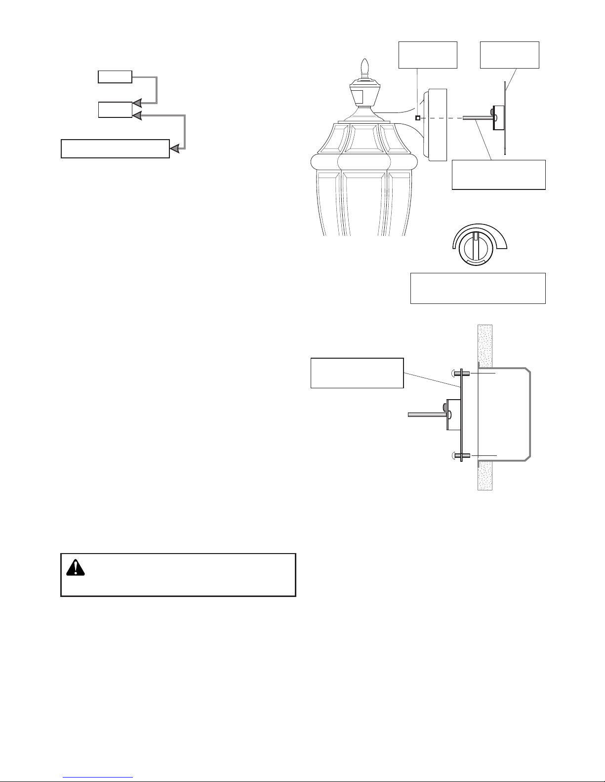
OPERATION
* resets to Auto Mode at dawn.
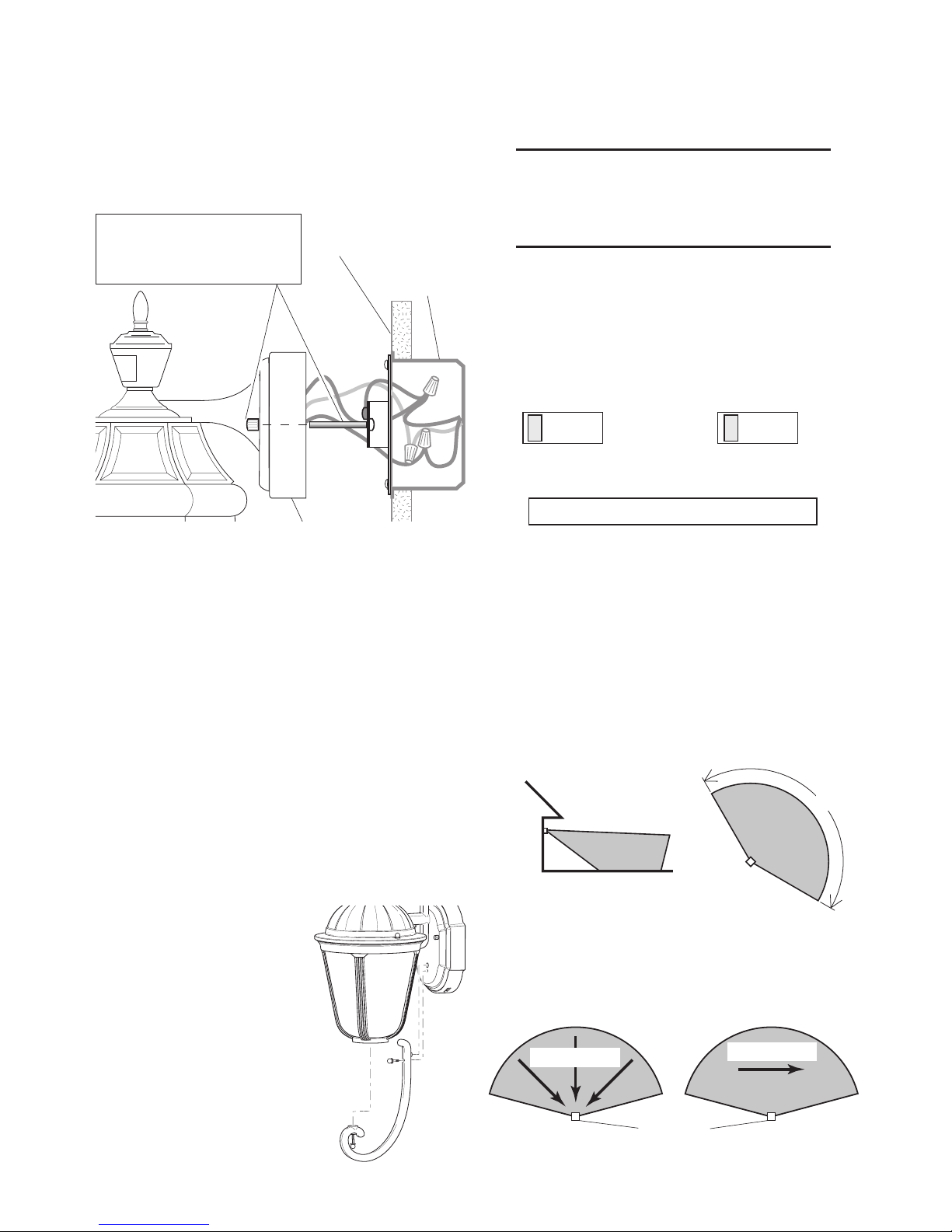
Set the ON-TIME switch
on the bottom of the cover
plate to TEST. TEST 1 5 10 MIN
Set ON-TIME switch to
1, 5, or 10 minutes.
1 Second
OFF then...
Manual mode only works at
night because daylight re-
turns the sensor to AUTO.
Flip the light switch off for
one second then back on to
toggle between AUTO and
MANUAL MODE.
Manualmodeworksonlywith
the ON-TIME switch in the 1,
5, or 10 position.
... back on.
Note: When first turned on wait about 1 1/2
minutes for the circuitry to calibrate.
TEST
AUTO
MANUAL MODE
TEST 1 5 10 MIN
Mode: On-Time Works: Day Night
Test 5 Seconds x x
Auto 1, 5, or 10 Min x
Manual To Dawn* x
Accent 3,6 Hr. to Dawn x
Before installation, record the model
number from back of fixture below.
Attach receipt in case of possible war-
ranty issues.
Questions or problems? Before returning
to your retailer, refer to the troubleshooting
guide in this manual or call our technical ser-
vice department at 1-800-858-8501 (English
speaking only), 7:30 am to 4:30 pm, CST,
Monday – Friday.
Features
• Lightcomesonwhenmotionisdetected.
• Automaticallyturnslightoff.
• DuskAccentlighting.
• Photocellkeepsthelightoffduringdaylight
hours.
Package Contents
• Lantern
• UniversalMountingBracket
• MountingScrews(Includesextralongscrew
studs for recessed junction box mounting)
• WireConnectors
Requirements
• Thelightcontrolrequires120voltsAC.
• IfyouwanttouseManualMode,thecontrol
must be wired through a switch.
• Some electrical codes require installa-
tion by a qualified electrician.
ON-TIME
ON-TIME
SL-4290 Series
Meets the ENERGY STAR®
guidelines when Du a l Brite®
function is off.
2598-1277-03
INSTALLATION
Estimated Installation Time: 30 minutes
Items needed for installation (not included):
• Phillipsandatheadscrewdrivers
• Pliers • Wirestrippers/cutters
• Safetyglasses • Lightbulb
• Siliconecaulk
Forbestperformance,mountthefixtureabout
6 feet (1.8 m) above the ground.
1. Remove
two nuts.
2. Remove
X-Bar.
Junction
Box
5. Attach X-Bar to
junction box
Due to the size and weight of the fixture, you
mayfindithelpfultohaveanassistantholdthe
fixture in place while connecting the wires.
MAX
MIN
3. Tighten screws
finger tight.
SENSITIVITY
4. Set sensitivity on fixture
back to the mid-position.
WARNING: Turn power off at circuit
breaker or fuse.
Mode Switching Summary
Du a l Br i t e ®Dimmer Control
Light comes on half bright for selected time
after dusk (Off, 3 hr., 6 hr., until dawn).
Selecting OFF disables this feature. The
motion sensing features will continue to
work as described in this manual. If motion
is sensed, the light turns on full bright for the
ON-TIME (1, 5, or 10 minutes) then returns
to dim mode.
ON-TIME Switch at 1,
5, or 10 minutes
Flip light switch
off for one second
then back on*
* If you get confused while switching modes,
turn the power off for one minute, then back
on.After the calibration time the control will
be in the AUTO mode.
MANUAL MODE
AUTO
TEST

3
598-1277-03
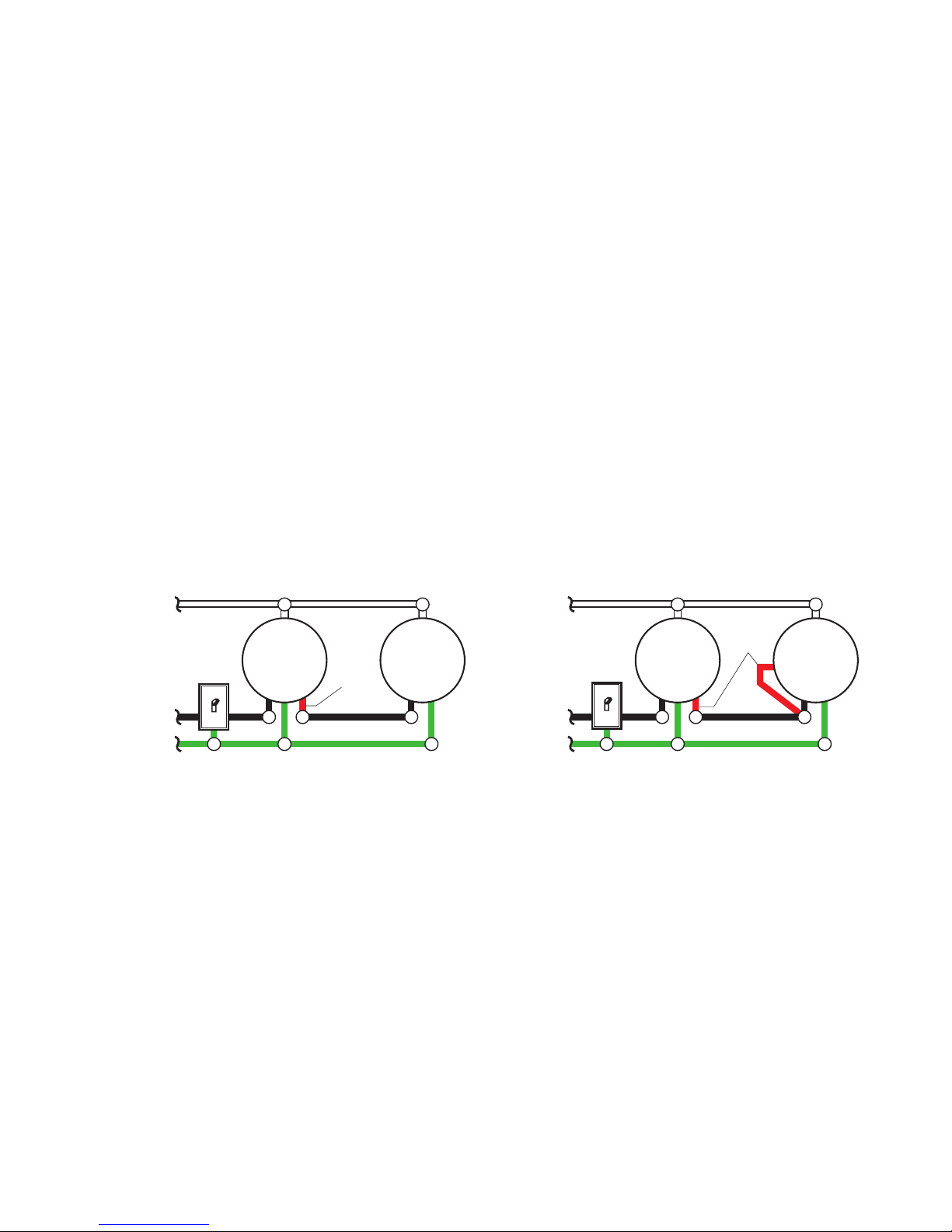
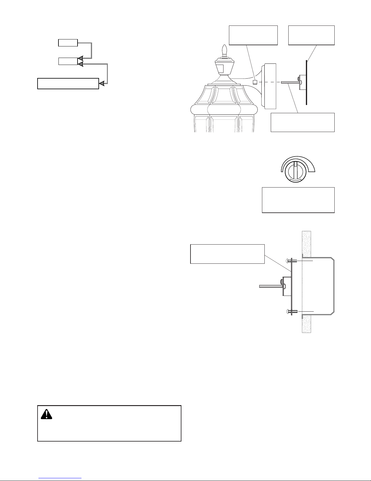
WIRING
One Motion Light
❒ Twist the junction box wires and the
fixture wires together as shown below.
Secure with wire connectors.If you have
a metal junction box, you may not need
thegreen“pigtail”.Ifyouare unsureabout
the grounding method, consult your local
building code.
Two Motion Lights
Black
White
Green
or Bare
Light
Fixture
Black
White
Green
or Bare
Light
Fixture
Light
Fixture
CAUTION: DO NOT connect the RED
wire unless you want to control other
lights from the motion sensor.
Note: All wiring should be run in accordance
with the National Electrical Code through
conduit or another acceptable means.
Contact a qualified electrician if there is
any question as to the suitability of the
system.
Connect the fixture wires to the wires in the
junction box. Twist the wires together and
secure with wire connectors.
Black to black White to white
Recommended Grounding Method
Use a green ground “pigtail” (not provided) and
twist one end together with the bare fixture wire
and the box ground wire. Secure with a wire
connector. Secure the other end of the “pigtail”
with the GND screw on the mounting plate.
4598-1277-03
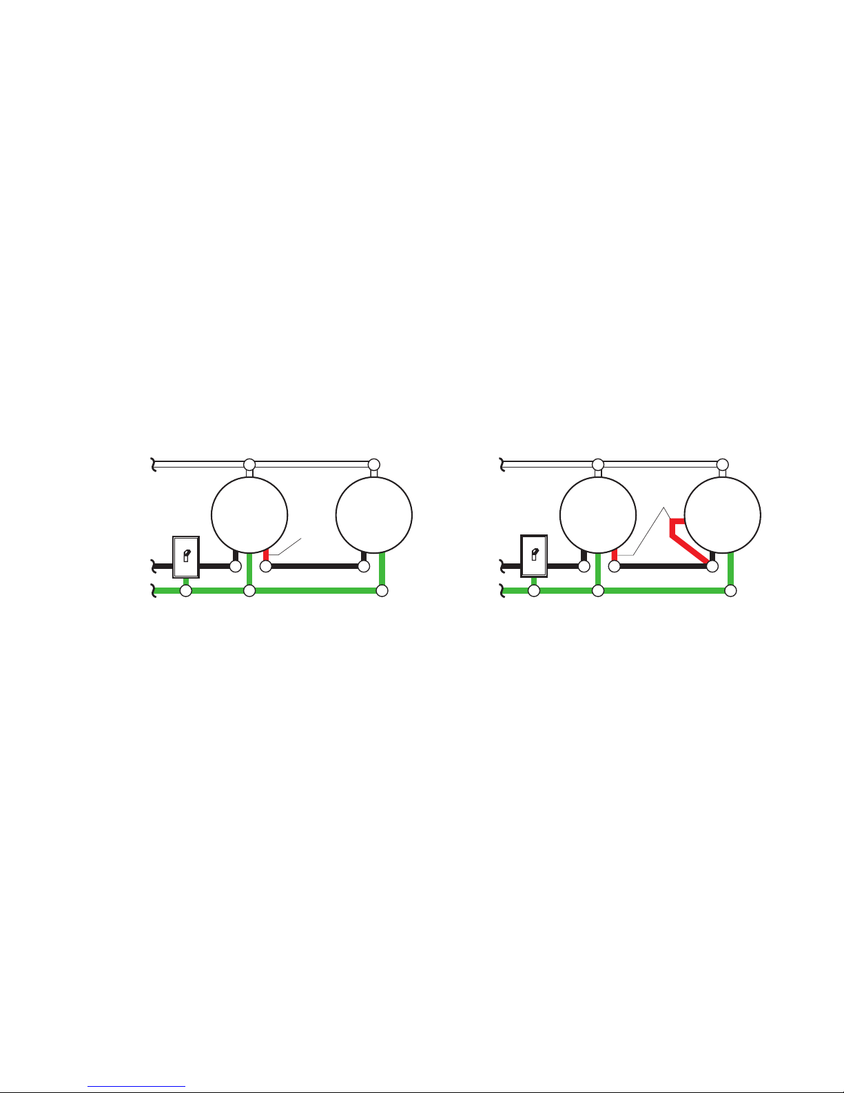
OPTIONAL WIRING
This fixture is provided with a sensor rated for 360 Watts. Since the fixture is only rated 100
Watts, 260 Watts of additional load may be controlled by this sensor.
When determining what a fixture is rated for, do not simply look at the rating on the lamp in
the fixture. Look at the marking which specifies the maximum lamp wattage for which the
fixture is suitable.
Once you have selected the fixtures to be connected and determined their maximum ratings,
add these ratings up. For instance, if you have 3 fixtures rated 100 Watts, 150 Watts, and
75 Watts respectively, you have a total load of 325 Watts.
Wiring Diagram 1 – When wiring to control a standard light fixture: Strip the motion sensor’s
red wire and connect to the standard light’s black wire. Connect all white wires together.
Total fixture ratings must not exceed 360 Watts (3.0 A).
Wiring Diagram 2 – When wiring to control another motion sensing light fixture (Master /
Slave):Strip the red wire in both light fixtures.Connect the red wire of the controlling (master)
fixture to the red and black wires of the controlled (slave) fixture. Connect all white wires
together. Total fixture ratings must not exceed 360 Watts (3.0 A).
Wiring Diagram 1
Black
White
Green
or Bare
Light
Fixture
Light
Fixture
Wiring Diagram 2
(Standard) Master Slave
It is also possible to wire two motion lights so that either fixture will turn on both lights at the
same time (dual master system). It is recommended that only people with plenty of electrical
experienceattemptthisconguration.Pleasecallourcustomerservicenumber(1-800-858-
8501 - English speaking only) before attempting this wiring. If the dual master wiring is not
done correctly, it can destroy both motion sensing fixtures and void your warranty.
Black
White
Green
or Bare
Light
Fixture
Light
Fixture
Red
Red
5
598-1277-03
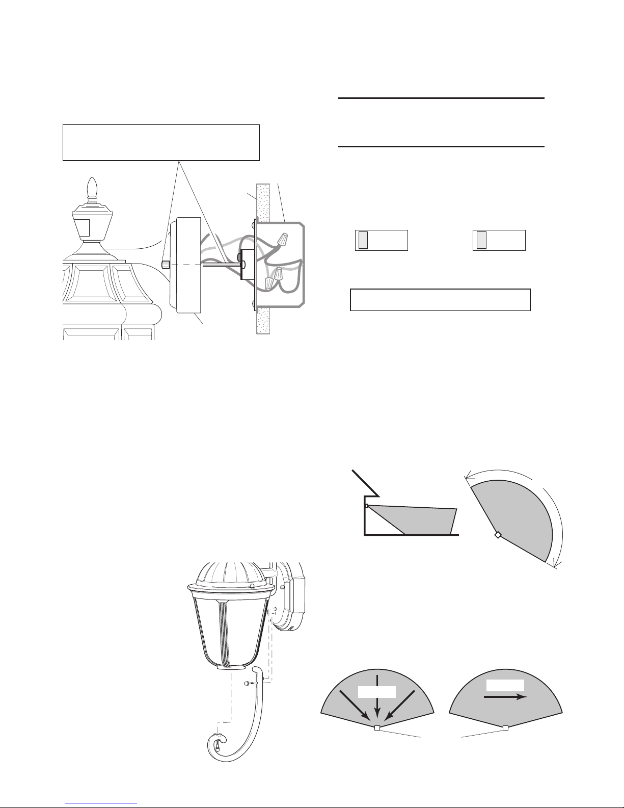
The detector is less sensitive to motion di-
rectly towards it and more sensitive to across
motion.
Sensor
Motion
Least Sensitive Most Sensitive
Avoid aiming the control at:
•Objectsthatchangetemperaturerapidly,
such as heating vents and air condition-
ers. These heat sources could cause false
triggering.
•Areaswherepets or traffic may trigger
the control.
•Nearby large, light-colored objects
reecting light may trigger the shut-off
feature. Do not point other lights at the
sensor.
30 ft.
(9.1 m)
Maximum Range Maximum
Coverage Angle
6 ft.
(1.8 m)
150°
COMPLETE THE
INSTALLATION
❒Stuff the wires into the junction box. Make
sure none of the wires get pinched.
Slide the fixture onto the mounting
screws and tighten nuts.
❒ Install light bulb (100 Watt maximum).
❒ Install the lower glass assembly (if
applicable). Secure with decorative
screws.
❒Aftercompletingthetests,caulkbetween
fixture canopy and mounting surface
with silicone weather sealant.
Junction
Box
Motion
LOWER ARM INSTALLATION
(4294 Only)
Model 4294 comes with a separate lower
arm. Follow the directions below to attach
the lower arm.
1. Complete the in-
stallation steps
above.
2. Usingthedecora-
tive screws pro-
vided, secure the
lower arm to the
canopy and the
bottomofthe low-
er glass assem-
bly as shown.
Canopy
Mounting
Surface
TESTING
❒Turn on the circuit breaker and light
switch.
Note: Sensor has a 1 1/2minute warm up pe-
riod before it will detect motion.When
first turned on, wait 1 1/2minutes.
Note: Meets the ENERGY STAR®guidelines
when Du a l Br i t e ®function is off.
❒Switch the on-time to TEST position and
Du a l Br i t e ®switch to the OFF position.
TEST 1 5 10 MIN
ON-TIME
OFF 3 6 DUSK TO
HOUR DAWN

6598-1277-03
❒If you need to change the sensitivity,
temporarily remove the fixture and make
the adjustment.Too much sensitivity may
increase false triggering.
❒Set the amount ofTIME you want the light
to stay on after motion is detected. (1, 5,
or 10 minutes).
❒Settheamount of time after duskyouwant
the lights on accent level.
SPECIFICATIONS
Range.........Up to 30 ft. (9.1 m) [varies with
surrounding temperature].
Sensing Angle ............................Up to 150°
Electrical Load.... Up to 100 Watt Maximum
Tungsten Incandescent
Sensor Capacity ..... Up to 360 Watt (3.0 A.)
Maximum Tungsten
Incandescent
PowerRequirements ......... 120 VAC, 60 Hz
Operating Modes............ TEST, AUTO, and
MANUAL MODE
Time Delay ........................1, 5, 10 minutes
Du a l Br i t e ®timer ......................Off, 3, 6 hrs,
Dusk-to-Dawn
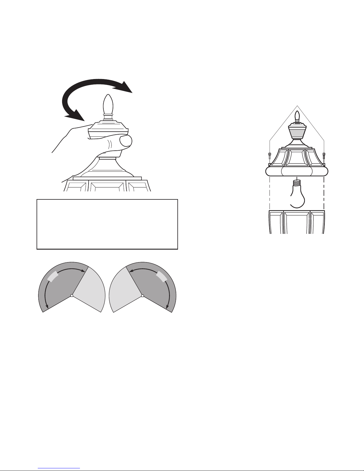
❒Walk through the coverage area noting
where you are when the lights turn on.
Move the sensor head left or right to
change the coverage area.
Rotating Sensor Head to Change
Coverage Area
IMPORTANT: Grasp the sensor only as
shown and turn the entire sensor. Any
other method may damage the sensor.
Do not force the sensor past the stop-
ping points.
1
5
0
°
1
5
0
°
BULB REPLACEMENT
If lantern has an open bottom, insert bulb
through opening and screw into socket.
If lantern has a closed
bottom, follow the steps
below to replace bulb.
1. Place one hand
under lower glass
assembly and un-
screw decorative
screws holding
lower glass as-
sembly to top of
fixture.
2. Replace bulb.
3. Reattach lower
glass assembly
to fixture top us-
ing decorative
screws.
Decorative Screws
Lower Glass
Assembly
Light
Bulb

7
598-1277-03
TROUBLESHOOTING GUIDE
SYMPTOM
Light stays
on continu-
ously.
Lightashes
on and off.
POSSIBLE CAUSE
1.
The sensor is pointed toward
a heat source like an air
vent, dryer vent, or brightly
painted,heatreective
surface (Reduce sensitivity).
2.
Light control is in Manual
Mode. (Switch to Auto.)
3. Light control is in
Du a l Br i t e ®mode.
4. Sensitivity is set too high.
(Reduce sensitivity.)
1. Light control is in the Test
mode and warming up
(Flashing is normal under
these conditions).
2.Heatbeingreectedfrom
other objects may be
affecting the sensor. (Re-
aim sensor.)
POSSIBLE CAUSE
1. Light switch is turned off.
2.
Bulb is loose or burned out.
3. Fuse is blown or circuit
breaker is turned off.
4. Daylight turn-off is in ef-
fect (recheck after dark).
5. Incorrect circuit wiring, if
this is a new installation.
1. Light control may be in-
stalled in a relatively dark
location.
2. Light control is in Test
(Set control switch to an
ON-TIME position).
1. Light control may be
sensing small animals or
automobile traffic (Reduce
sensitivity).
SYMPTOM
Light will not
come on.
Light comes
on in daylight.
Light comes
on for no
apparent
reason.
TECHNICAL SERVICE
Please call 1-800-858-8501 (English speaking only) for assistance before returning
product to store.
If you experience a problem, follow this guide. You may also want to visit our Web site at:
www.hzsupport.com.Iftheproblempersists,call* forassistance at1-800-858-8501(English
speaking only),8:00AMto5:00PMCST(M-F).Youmayalsowrite*to:
HeathCo LLC
P.O.Box90045,BowlingGreen,KY42102-9045
ATTN: Technical Service
* If contacting Technical Service, please have the following information available: Model
Number,DateofPurchase,andPlaceofPurchase.
No Service Parts Available for this Product
Please keep your dated sales receipt, it is required for all warranty requests.

8598-1277-03
HeathCo LLC reserves the right to discontinue products and to change specifications at
any time without incurring any obligation to incorporate new features in products previously
sold.
TWO YEAR LIMITED WARRANTY
This is a “Limited Warranty” which gives you specific legal rights.You may also have other rights
which vary from state to state or province to province.
For a period of two years from the date of purchase, any malfunction caused by factory defective
parts or workmanship will be corrected at no charge to you.
Not Covered - Repair service, adjustment and calibration due to misuse, abuse or negligence,
light bulbs, batteries, and other expendable items are not covered by this warranty. Unauthorized
service or modification of the product or of any furnished component will void this warranty in its
entirety.This warranty does not include reimbursement for inconvenience, installation, setup time,
loss of use, unauthorized service, or return shipping charges.
ThiswarrantycoversonlyHeathCoLLCassembledproductsandisnotextendedtootherequip-
ment and components that a customer uses in conjunction with our products.
THISWARRANTY ISEXPRESSLYINLIEUOFALLOTHERWARRANTIES,EXPRESSOR
IMPLIED,INCLUDINGANYWARRANTY,REPRESENTATIONORCONDITIONOFMERCHANT
ABILITYORTHATTHEPRODUCTSAREFITFORANYPARTICULARPURPOSEORUSE,
ANDSPECIFICALLYINLIEUOFALLSPECIAL,INDIRECT,INCIDENTAL,ORCONSEQUEN-
TIAL DAMAGES.
REPAIRORREPLACEMENTSHALLBETHESOLEREMEDYOFTHECUSTOMERANDTHERE
SHALLBENOLIABILITYONTHEPARTOFHEATHCO LLCFORANYSPECIAL,INDIRECT,
INCIDENTAL, OR CONSEQUENTIAL DAMAGES, INCLUDING BUT NOT LIMITEDTO ANY
LOSSOFBUSINESS ORPROFITS,WHETHERORNOTFORESEEABLE. Somestatesor
provincesdonotallowtheexclusionorlimitationofincidentalorconsequentialdamages,sothe
above limitation or exclusion may not apply to you.
Please keep your dated sales receipt, it is required for all warranty requests.

FUNCIONAMIENTO
*Se pone en Automático al amanecer.
© 2010 HeathCo LLC 598-1277-03 S
PRUEBA
ON-TIME
Pongaelinterruptordetiem-
po (ON-TIME), al fondo del
detector, en la posición de
prueba (TEST). TEST 1 5 10
1 segundo
APAGADO
luego...
El modo manual funciona sólo
porlanocheporquelaluzdel
día pone al detector en modo
AUTOMATICO.
Apague el interruptor por un
segundo y vuélvalo a prender
para conmutar entre MODO
AUTOMATICO y MANUAL.
El modo manual funciona sólo
cuandoelinterruptordetiempo
(ON-TIME) está en la posición
de 1, 5 o 10 minutos.
ON-TIME
TEST 1 5 10
Pongaelinterruptordetiem-
po (ON-TIME) en la posición
de 1, 5 o 10 minutos.
MODO MANUAL
...préndalo.
AUTOMATICO
Nota: Cuando lo prenda por primera vez es-
pere 1 1/2minutosparaqueelcircuito
se calibre.
Modalidad: A tiempo:
Trabaja:
Día Noche
Prueba 5 segundas x x
Autom. 1, 5, o 10 min. x
Manual Hasta el ama-
necer*
x
Adorno 3,6 hrs, hasta
el amanecer
x
Farol Du a l Br i t e ®de
fundición con detector
de movimiento
¿Preguntas o problemas? Antes de
devolver el producto al minorista, lea
la guía de análisis de averías en este
manual o llame a nuestro departamento de
servicio técnico al 1-800-858-8501 (sólo se
habla inglés), de 7:30 am a 4:30 pm, Hora
Estándar del Centro, de Lunes a Viernes.
Características
• Laluzseprendecuandosedetectamovi-
miento.
• Apagalaluzautomáticamente.
• Iluminaciónornamentaldebajaintensidad.
• La fotocélula mantiene la luz apagada
durante las horas del día.
Contenidos del Paquete
• Farol
• Soporte de montaje universal
• Tornillos de montaje (se incluyen espárra-
gosextralargosparatornillosparamontaje
empotrado de la caja de empalme).
• Conectoresdealambre
Requisitos
• Elcontroldeluzrequiere120VCA.
• ParausarelSobrecontrolManual,conecte
el control con un interruptor.
• Algunos códigos requieren instalación
por un electricista calificado.
Serie SL-4290
Cumple con las normas ENER-
GY STAR®cuando la función
Du a l Br i t e ®está apagada.

10 598-1277-03
Luz de Adorno (Du a l Br i t e ®)
La luz se prende con media brillantez por
el tiempo escogido después del atardecer
(apagado, 3 hr., 6 hrs., hasta el amanecer).Si
escogeOFF(APAGADO)deshabilitaestafun-
ción.Lasfuncionesquedetectanmovimiento
continuarán funcionando como se describen
en este manual. Si detecta movimiento, la
luz se prende con todo su resplandor por el
tiempo de duración o de ON-TIME (1, 5 o 10
minutos) y luego regresa a media luz.
Mueva el interruptor de
tiempo (ON-TIME) a 1, 5 o
10 minutos
Apague el interruptor
por un segundo y
préndalo de nuevo*
PRUEBA
AUTOM.
MODO
MANUAL
* Si se confunde mientras cambia de fases,
apague la electricidad por un minuto y
préndala de nuevo. Después del tiempo
de calibración el control estará en fase
AUTO(MATICA).
Resumen de las modalidades del
interruptor
5. Monte el soporte X-Bar
a la caja de empalme.
4. Fije de nuevo el alcance
de sensibilidad a la posición
del medio.
2.Quitelabanda
"X" de montaje.
3. Ajuste los tornillos
tan sólo con los dedos.
MAX
MIN
SENSIBILIDAD
la caja de
empalme
Debido al tamaño y peso del aparato, será
prudentequesuasistentesotengaelaparato
mientras se conectan los cables.
INSTALACION
Tiempo estimado de instalación: 30
minutos
Artículosquesenecesitanparala
instalación (no incluidos):
• TornillosPhillipsydecabezaplana
• Alicates
• Desforrador/cortadordealambre
• Lentesdeseguridad
• Bombilla
• Calafateodesilicona
Para un mejor funcionamiento, instale el
aparato a casi 1.8 m del suelo.
ADVERTENCIA:Desconecte laener-
gía en el disyuntor.
1.Quitelas
dos tuercas.

11
598-1277-03
Negro a negro Blanco a blanco
Método recomendado de conexión a tierra
Useun“cableexible”verdedetierra(nopro-
visto) y tuerza un extremo con el cable desnudo
del aparato y con el cable de a tierra de la caja.
Asegúrelos con un conector de cables.Asegure
elotroextremodel“cableexible”coneltornillo
de a tierra de la placa de montaje.
Conecte los alambres del aparato a los
alambres de la caja de empalme. Tuerza
juntos los alambres y asegúrelos con
conectores de alambre.
CABLEADO
Luz de un movimiento
❒ Tuerza los cables de la caja de empalme
con los cables del aparato, como se
muestraabajo.Asegúrelosconconectores
de cables. Si tiene una caja de empalme
demetal,nonecesitael“cableexible”.
Si no está seguro del método de conexión
a tierra, consulte con el código local de
construcción.
Luz de dos movimientos
Negro
Blanco
Verde o
Desnudo
Aparato
de Luz
Negro
Blanco
Verde o
Desnudo
CUIDADO:NOconecteelcableROJO
exceptoquedeseecontrolarotrasluces
desde el detector de movimiento.
Nota: Todo el cableado debe realizarse de
acuerdo con el Código Eléctrico Nacional
usandotubería o algún otro medioaceptable.
Póngase en contacto con un electricista
calificado si tiene alguna pregunta
referente a la aptitud del sistema.
Aparato
de Luz
Aparato
de Luz
12 598-1277-03
Estambiénposibleconectardoslucesdetectorasdemovimientodemaneraquecada
aparato prenda ambas luces al mismo tiempo (sistema de doble maestro). Se recomienda
quesólopersonasconampliosconocimientosdeelectricidadconectenestetipodecon-
guración.Porfavorcomuníqueseconnuestrodepartamentodeasistenciaalcliente(1-
800-858-8501 - sólo para hablar en inglés) antes hacer este tipo de conexión. La conexión
inadecuada del cableado de doble maestro podría dañar ambas luces de movimiento
y anular la garantía.
CONEXION ALTERNA
Esteaparatovieneconundetectorconunapotenciade360Vatios.Puestoqueelaparato
tiene sólo una potencia de 100 Vatios, la carga adicional de 260 Vatios puede ser controlada
por el detector.
Cuando desee determinar la clasificación de un aparato no vea tan sólo la potencia de la
lámpara.Mirelaindicaciónqueespeciqueelvoltajemáximodelalámparaqueelaparato
puede aceptar.
Unavezquehaescogidolosaparatosqueseconectarányhadeterminadosusmáximas
potencias,súmelas.Porejemplo,sitiene3aparatosde100,150y75Vatiosrespectivamente,
usted tendrá un total de 325 Vatios.
Diagrama de Cableado 1 – Cuando prepare una conexión para controlar un aparato de luz
estándar:Peleelalambrerojodeldetectordemovimientoyconécteloalalambrenegrode
la luz estándar. Conecte todos los alambres blancos. La capacidad total no debe exceder
los 360 Vatios (3.0 A).
Diagrama de Cableado 2 – Cuando prepare una conexión para controlar otro aparato de
luzdetectordemovimiento(Maestra/Esclava):Peleelalambrerojoenambosaparatosde
luz. Conecte el alambre rojo del aparato controlador (maestro) a los alambres rojo y negro
del aparato controlado (esclavo). Conecte todos los alambres blancos. La capacidad total
no debe exceder los 360 Vatios (3.0 A).
Diagrama de Cableado 1
Negro
Blanco
Verde o
Desnudo
Diagrama de Cableado 2
(Estándar) Maestra Esclava
Rojo
Rojo
Aparato
de Luz
Aparato
de Luz
Negro
Blanco
Verde o
Desnudo
Aparato
de Luz
Aparato
de Luz
13
598-1277-03
Movimiento
Detector
150°
COMPLETE LA
INSTALACION
❒Meta los cables en la caja de empalme.
Asegúresequeloscablesquenoestén
pinchados.
❒ Instale la bombilla (100 Vatios máximo).
❒ Instale el conjunto del vidrio inferior (si
es aplicable). Asegúrela con tornillos
decorativos.
❒Después de completar las pruebas, cala-
fatee entre el escudete del aparato y la
superficie de montaje con un sellador de
silicona contra la intemperie.
Deslice al apartato sobre
los tornillos de montaje y
ajuste las tuercas. la caja de
empalme
Alcance Máximo Angulo de
Cobertura Máxima
9.1 m
1.8 m
Evite apuntar el control hacia:
•Objetosquecambienrápidamentedetem-
peraturatalescomoductosdecalefacción
yacondicionadoresdeaire.Estasfuentes
de calor pueden causar falsas alarmas.
•Areasdondeanimales domésticos o el
tráfico puedan activar el control.
•Losobjetosgrandescercanosydecolores
resplandecientesquereejanlaluzdeldía
puedenhacerqueeldetectorseapague.
No apunte otras luces hacia el detector.
Lo menos sensible Lo más sensible
El detector es menos sensible al movimiento
quesedirigedirectamentehaciaél.
Movimiento
INSTALACIÓN DEL BRAZO
INFERIOR (Sólo para el 4294)
El modelo 4294 viene con un brazo inferior
separado. Siga las indicaciones de abajo
para sujetar el brazo inferior.
1. Complete los pasos
deinstalación indica-
dos arriba.
2. Usando los tornillos
decorativos que se
proveen, asegure el
brazo inferior al es-
cudete y la parte de
abajodelconjuntodel
vidrio inferior como
se muestra.
Escudete
Superficie de
montaje
PRUEBA
❒Prendaelcortacircuitosyelinterruptor
de luz.
Nota: El detector tiene un período de cerca
de 1 1/2minutos de calentamiento antes
dedetectarmovimiento.Cuandoloprenda
por primera vez, espere 1 1/2minutos.
Nota: Cumple con las normas ENERGY
STAR®cuando la función Du a l Br i t e ®está
apagada.
❒Fije el de adorno (Du a l Br i t e ®) a apagado
(OFF)yelcontroldeON-TIMEalaposición
de prueba (TEST).
TEST 1 5 10 MIN
ON-TIME
OFF 3 6 DUSK TO
HOUR DAWN
14 598-1277-03
ESPECIFICACIONES
Alcance . . . . . . . . . . . Hasta 9.1 m (varía con la
temperatura del medio ambiente)
Angulo de detección . . . . . . . . . . . . Hasta 150°
Carga Eléctrica . . . . . . . . . Hasta un máximo de
100 Vatios de tungsteno
incandescente
Capacidad del Detector...Hasta un máximo de
360 Vatios (3.0 A.) de
tungsteno incandescente
RequisitosdeEnergía ........120 VCA, 60 Hz
Fases de Operación . . . . . . . . . . . . . .PRUEBA,
AUTOMATICO y MODO MANUAL
Retardo de Tiempo . . . . . . . . . .1, 5, 10 minutos
Temporizador
Du a l Br i t e ®..........Apagado, 3, 6 horas, del
atardecer al amanecer
❒ Sinecesitacambiarlasensibilidad,quite
el aparato por un rato y haga el ajuste.
Demasiada sensibilidad puede aumentar
la falsa alarma.
❒ Fijeelperíododetiempo(ON-TIME)que
laluzdebequedarseprendidadespuésde
detectar movimiento (1, 5 o 10 minutos).
❒Determine la cantidad de tiempo después
delanocherqueustedquierequelaluz
permanezca al nivel de acento.
❒Camineporeláreadeproteccióndándose
cuentadónde estácuandola luzseprende.
Mueva la cabeza del detector hacia la
izquierdaoderechaparacambiarelárea
de protección.
Giro de la cabeza del detector para
cambiar el área de cobertura
1
5
0
°
1
5
0
°
IMPORTANTE: Agarre el detector sólo
como se muestra y gire todo el detector.
Cualquier otro método puede dañar el
detector. No fuerce al detector más allá
de sus puntos tope.
REEMPLAZO DE LA
BOMBILLA
Si el farol tiene un fondo abierto, inserte la
bombilla por la apertura y atorníllela en el
enchufe.
Si el farol tiene un fondo cerrado, siga los
siguientes pasos para cambiar la bombilla.
1. Ponga una mano
debajo del con-
junto inferior de
vidrio y quite los
tornillos decorati-
vosquesostienen
el conjunto inferior
de vidrio a la parte
superior delapara-
to.
2. Reemplace la
bombilla.
3. Fije de nuevo el
conjunto inferior
de vidrio a la parte
superior delapara-
to con los tornillos
decorativos.
Anillos decorativos
Conjunto inferior
de vidrio
Bombilla

15
598-1277-03
GUIA DE INVESTIGACION DE AVERIAS
SINTOMA
La luz se
queda
prendida
continua-
mente.
La luz se
prendeyse
apaga.
POSIBLE CAUSA
1. El sensor puede detectar fuentes
de calor, como ductos de cale-
facción y de aire acondicionado,
o superficies resplandecientes
que reejan la luz (Reduzca la
sensibilidad).
2. El control de luz está en fase
Manual (Cámbiela a Auto).
3. El control de luz está en fase
Du a l Br i t e ®.
4. La Sensibilidad es demasiado
alta. (Reduzca la sensibilidad).
1. El control de luz está en fase
de Prueba y calentándose (El
prenderse y apagarse es normal
bajo estas condiciones. Apague
el Aumento).
2. Elcalorquesereejadeotros
objetos pueden estar afectando
al detector. (Reposicione el de-
tector).
SINTOMA
La luz no
se encien-
de.
La luz se
prende
durante el
día.
La luz se
prende sin
ninguna
razón apa-
rente.
POSIBLE CAUSA
1.
El interruptor de luz está apagado.
2. Elfaroestáojoofundido.
3. El fusible está quemado o el
cortacircuitos está apagado.
4. La desconexión de luz del día
está en efecto. (Compruébelo
al anochecer).
5. Alambrado incorrecto, si ésta es
una nueva instalación.
1. El control de luz puede estar ins-
talado en un lugar relativamente
oscuro.
2.
El control de luz está en fase de
Prueba.(Fije el interruptor del con-
trol a la posición de TIEMPO).
1. El control de luz puede estar de-
tectandoanimalespequeñosoel
trásito de automóviles (Reduzca
la sensibilidad).
SERVICIO TÉCNICO
Favor de llamar al 1-800-858-8501 (sólo para hablar en inglés) para pedir ayuda
antes de devolver el producto a la tienda.
Si tiene algún problema, siga esta guía. Usted puede también visitar nuestro sitio Web:
www.hzsupport.com. Si el problema continúa, llame al 1-800-858-8501 (sólo para ha-
blareninglés),de8:00AMa5:00PMCST(L-V).Ustedpuedetambiénescribira:
HeathCo LLC
P.O.Box90045,BowlingGreen,KY42102-9045
ATTN: Technical Service (Servicio Técnic)
* Si se llama al Servicio Técnico, por favor tener lista la siguiente información: Número de
Modelo, Fecha de compra y Lugar de compra.
No hay piezas de servicio disponibles para este producto.
Por favor guarde su recibo de venta fechado; se lo requiere para cualquier solicitud
de garantía.

16 598-1277-03
HeathCoLLCsereservaelderechodedescontinuarproductosydecambiarespecificaciones
acualquiermomentosinincurrirenningunaobligacióndetenerqueincorporarnuevas
características en los productos vendidos con anterioridad.
GARANTÍA LIMITADA A 2 AÑOS
Estaesuna“GarantíaLimitada”queledaaUd.derechoslegalesespecícos.Ustedpuede
tambiéntenerotrosderechosquevaríandeestadoaestadoodeprovinciaaprovincia.
Porunperíodode2añosdesdelafechadecompra,cualquiermalfuncionamientoocasionado
por partes defectuosas de fábrica o mano de obra será corregido sin cargo para Ud.
No cubierto - Servicio de reparación, ajuste y calibración debido al mal uso, abuso o negligencia,
bombillas, baterías, u otras partes fungibles no están cubiertas por esta garantía. Los Servicios no
autorizadosomodicacionesdelproductoodecualquiercomponentequeseproveeinvalidarán
esta garantía en su totalidad. Esta garantía no incluye reembolso por inconveniencia, instalación,
tiempo de instalación, perdida de uso, servicio no autorizado, o costos de transporte de retorno.
Esta garantía cubre solamente los productos ensamblados por HeathCo LLC y no se extiende a
otrosequiposocomponentesqueelconsumidorusajuntoconnuestrosproductos.
ESTAGARANTÍAESTÁEXPRESAMENTEENLUGARDEOTRASGARANTÍAS,EXPRESADAS
OSOBREENTENDIDAS,INCLUYENDOCUALQUIERGARANTÍA,REPRESENTACIÓNOCON-
DICIÓNDECOMERCIABILIDADOQUELOSPRODUCTOSSEADAPTENPARACUALQUIER
PROPÓSITOOUSOENPARTICULAR,YESPECIFICAMENTEENLUGARDETODOSLOS
DAÑOSESPECIALES,INDIRECTOS,INCIDENTALESYCONSECUENTES.
LAREPARACIÓNOELREEMPLAZODEBERÍASERLAÚNICASOLUCIÓNDELCLIENTEY
NOHABRÁRESPONSABILIDADPORPARTEDEHEATHCO LLCPORCUALQUIERDAÑO
ESPECIAL,INDIRECTO,INCIDENTALOCONSECUENTE,INCLUIDOSPERONOLIMITADOS
ACUALQUIERPÉRDIDADENEGOCIOOGANACIASSEANONOPREVISIBLES.Algunos
estados o provincias no permiten la exclusión o limitación de daños incidentales o consecuentes,
demodoquelalimitaciónoexclusiónarribaindicadapuedequenoseapliqueaUd.Por favor
guarde su recibo de venta fechado; se lo requiere para cualquier solicitud de garantía.

17
598-1277-03
© 2010 HeathCo LLC 598-1277-03 F
FONCTIONNEMENT
*Revientaumodeautomatiqueauleverdusoleil.
Note: Aprèsmiseencircuit,attendreenfiron
1 1/2minutepourquel’étalonnagedu
circuit soit complété.
Le mode manuel ne fonc-
tionnequelanuitparceque
la lumière du jour remet le
capteur en mode AUTO.
Mettrel’interrupteurhorscir-
cuit pendant une seconde,
plus en circuit pour alterner
entre les modes AUTO et
MANUEL.
Le mode manuel ne fonc-
tionne que lorsque l’inter-
rupteur ON-TIME est aux
positions 1, 5 ou 10.
hors circuit
pendant 1
seconde,
puis ...
... à nouveau
en circuit
Amenerenposition d’essai
(TEST) l’interrupteur de
tempsencircuit(ON-TIME)
du bas du détecteur.
ON-TIME
TEST 1 5 10 MIN
ON-TIME
TEST 1 5 10 MIN
ESSAI
AUTOMATIQUE
PRIORITÉ MANUELLE
Amener l’interrupteur de
temps en circuit (ON-TIME)
à la position correspondant
à 1, 5 ou 10 minutes.
Lanterne moulée sous
pression Du a l Br i t e MD à
détecteur de mouvement
Mode: Temps en circuit: En fonction:
Jour Nuit
Essai 5 secondes x x
Auto 1, 5, ou 10 min. x
Manuel Auchoix, amanecer* x
Accentua-
tion
3,6hjusqu'àl'aurore x
Des questions ou problèmes? Avant de
vous rendre chez le détaillant, consultez
la section Dépannage de ce guide ou
communiquez avec le service technique
au 1 800 858-8501 (en anglais seulement)
du lundi au vendredi entre 7 h 30 et 16 h
30, HNC,.
Caractéristiques
• Allume l’éclairage lorsqu’un mouvement
est détecté.
• Éteintautomatiquementl’éclairage.
• Éclairaged'accentuationdecrépuscule.
• Photocellulequimaintientl’éclairageéteint
pendant la période de lumière du jour.
Contenu de l’emballage
• Lanterne
• Support de montage universel
• Vis de montage (y compris des vis très
longues pour l’installation dans des boîtes
de raccordement encastrées)
• Serre-ls
Exigences
• Lacommanded'éclairagenécessiteune
alimentation 120 volts c.a.
• Sivousdésirezutiliserlaprioritémanuelle,
la commande doit être branchée à un in-
terrupteur.
• Certains codes de bâtiment locaux peu-
vent exiger que l’installation soit faite
par un électricien qualifié.
Série SL-4290
Conforme aux exigences
ENERGY STARMD lorsque la
fonction Du a l Br i t e MD est dé-
sactivée.
18 598-1277-03
1. Enlevez les
deux écrous.
2. Enlevez la
barre-X.
Boîte de
jonction
5. Fixez la barre-X à la
boîte de jonction.
À cause de la taille et du poids du luminaire,
vous pourriez trouver utile de vous aider par
unepersonnequitiendraleluminairependant
quevousraccordezlesls.
MAX
MIN
4. Réglez la sensibilité
àmi-positionàl'arrière
du luminaire.
3. Resserrez les vis
avec les doigts.
SENSIBILITÉ
Minuterie Du a l Br i t e MD
La lumière s'allume à mi-intensité pour le
temps choisi après le crépuscule [Off (hors
circuit)3h,6h,jusqu'àl'aurore].Pourdésac-
tiver cette fonction, placez le commutateur à
OFF.La fonction de détection de mouvement
continueratoutefoisdefonctionnertelque
décrit dans ce guide. Si un mouvement est
détecté,lalumières'allumeàpleineinten-
sité pour le temps (ON-TIME) choisi (1, 5
ou 10 minutes), puis revient en mode faible
intensité.
Placer l’interrupteur ON-
TIME à 1, 5 ou 10 minutes
Mettre l’interrupteur
hors circuit pendant
une seconde, puis le
remettre en circuit
Résumé du mode de commutation
PRIORITÉMANUELLE
AUTO
TEST
* Si vous ne savez plus dans quel mode
se trouve l’appareil, couper l’alimentation
pendant une minute puis la rétablir. Après
le temps d’étalonnage, la commande re-
viendra au mode AUTO.
INSTALLATION
Temps estimatif d’installation : 30 minutes.
Articles nécessaires à l’installation (non
fournis) :
• Tournevis à lame droite et cruciforme
(Phillips)
• Pinces
• Pincesàdénuderouàcouper
• Lunettesdeprotection
• Lampeélectrique
• Produitdecalfeutrageàbasedesilicone
Pourunrendementoptimal,montezlelumi-
naire à environ 1,8 m au-dessus du sol.
MISE EN GARDE : Coupez
l’alimentation au disjoncteur ou au
fusible.

19
598-1277-03
Noir à noir Blanc à blanc
CÂBLAGE
Méthode de mise à la terre recommandée
Utilisezune«queuedecochon»verte(non
fournie) et torsadez-en une extrémité avec
le fil nu du luminaire et le fil de terre de la
boîtedejonction.Utilisezunserre-fils.Fixez
l'autreextrémitédela«queuedecochon»
aveclavisdeterre(GND)surlaplaque
de montage.
AVERTISSEMENT:NEPASraccorder
lefilROUGEàmoinsquevousnevouliez
commander d’autres luminaires au
moyen du détecteur de mouvement.
Note : Tous les fils doivent être installés
dans un conduit ou un autre dispositif
acceptable, conformément au Code national
de l’électricité. Contactez un électricien
qualifié pour toute question relative à la
pertinence de l’installation.
Branchez les fils du luminaire aux fils dans
la boîte de raccordement. Torsadez ces fils
ensemble, puis ajoutez-y un connecteur de
fils.
Une lanterne à détecteur de mouvement
Deux lanternes à détecteur de mouvement
Noir
Blanc
Vert ou
dénudé
Luminaire
Noir
Blanc
Vert ou
dénudé
❒Torsadez ensemble les fils de la boîte
de jonction et ceux du luminaire comme
indiquéci-dessous.Utilisezdesserre-ls.
Si la boîte de jonction est en métal, vous
pourriez nécessiterune «queue deco-
chon»verte.Sivousavezdesdoutessur
la méthode de mise à la terre, consultez
votre code du bâtiment.
LuminaireLuminaire

20 598-1277-03
Ilestaussipossiblederaccorderdeuxluminairesàdétectiondemouvementdesorteque
l’un ou l’autre des appareils allume simultanément les deux luminaires (double circuit maître).
Ilestrecommandéqueseulsdesgenspossédantunegrandeexpériencedel’électricité
tentent de réaliser cette configuration. Avant d’entreprendre ce type de câblage, veuillez
communiqueravecnotreServiceàlaclientèleau1800858-8501(serviceenanglaisseule-
ment). Si le câblage d’une installation à deux luminaires principaux n’est pas exécuté
correctement, il pourrait entraîner la destruction des deux luminaires à détection de
mouvement et annuler votre garantie. Nous nous excusons de ne pas pouvoir répondre
àvosquestionsenfrançaispartéléphone.
Diagramme de câblage 1
Noir
Blanc
Vert ou
dénudé
Diagramme de câblage 2
(Standard) Maître Satellite
Noir
Blanc
Vert ou
dénudé
CÂBLAGE FACULTATIF
Celuminaireestpourvud'uncapteurde360W.
Puisqueleluminaireauneintensitédeseulement
100 W, un luminaire additionnel de 260 W peut être contrôlé par ce capteur.
Lorsquevousdéterminezl'intensitéquepeutsupporterunluminaire,nevouscontentezpasde
simplementlirel'intensitéindiquéesurl'ampoule.Recherchezl'étiquetteindiquantlewattage
d'ampoulemaximaldel'appareil.
Unefoisquevousavezchoisilesluminairesàraccorderetdéterminéleurintensitémaximale
respective,additionnezlesintensités.Parexemple,sivousavex3appareilsdontl'intensité
est 100 Watts, 150 Watts et 75 Watts respectivement, la charge totale est 325 Watts.
Diagramme de câblage 1 – Câblage d’un luminaire standard : Dénudez le fil rouge du
détecteur de mouvement et raccordez-le au fil noir du luminaire standard. Branchez tous
leslsblancsensemble.L'intensitémaximalenedoitpasdépasser360Watts(3,0A).
Diagramme de câblage 2 – Câblage d’un autre luminaire à détecteur de mouvement (Maître
/ Satellite) : Dénudez le fil rouge des deux luminaires. Branchez le fil rouge du luminaire de
commande (maître) aux fils rouge et noir du luminaire commandé (satellite). Branchez tous
leslsblancsensemble.L'intensitémaximalenedoitpasdépasser360Watts(3,0A).
Rouge
Rouge
Luminaire Luminaire Luminaire Luminaire
Table of contents
Languages:
Other Heath Zenith Lantern manuals

Heath Zenith
Heath Zenith DualBrite Triple Halogen Motion Sensing Light... User manual

Heath Zenith
Heath Zenith SL-4190 Series User manual

Heath Zenith
Heath Zenith 4190 Series User manual

Heath Zenith
Heath Zenith DualBrite PF-4291-BK User manual

Heath Zenith
Heath Zenith 4395 User manual

Heath Zenith
Heath Zenith 598-1041-04 User manual

Heath Zenith
Heath Zenith SL-4190 Series User manual

Heath Zenith
Heath Zenith DualBrite 4290 Series User manual


