Heathkit HD-1410 User manual

HEATHKIT
HD-1410
ELECTRONIC KEYER

INTRODUCTION
The HD-1410 is a compact Electronic Keyer with a built in AC power supply, mechanical paddles,
sidetone oscillator and spea er in one pac age. It is designed and styled to complement the "SB"
Series and is compatible with virtually all modern transmitters and transceivers, as well as most
older rigs.
The following features ma e the Electronic Keyer versatile:
"Iambic" operation – Lets you form many Morse code characters with less wrist movement
than is required with eyers that lac this feature. If the two independent paddles are treated
as one, operation is identical to single-paddle eyers with dot and dash memories. Dots and
dashes are self-completing, and proper ratio is always maintained.
Built-in sidetone oscillator and spea er with adjustable tone and volume.
Headphone jac an the rear panel that silences the spea er. Receiver audio is fed to the head-
phones by a separate rear panel jac .
Built-in paddles have excellent "feel" and easily adjustable for tension and travel.
Solid-state output eliminates the bounce and stic ing problems associated with relays.
Weighted cabinet to prevent the eyer from sliding on the operating surface.
Rear panel jac s are provided for an external ey and for operation from an external battery
(polarity protected) for portable operation. The line cord disconnects from the Electronic Keyer
for battery operation.
Front panel "Hold" switch allows transmitter tune-up.
Low profile styling and small size permit the Electronic Keyer to be set in front of most Ham rigs
and not bloc controls or ta e up valuable space. The versatility and reliability of this Keyer will
ma e it a welcome addition to your Ham station for years to come.

OPERATION
The HD-1410 Electronic Keyer is an iambic or "squeeze" eyer. As such, this Keyer has two inde-
pendent paddles, one for dots and one for dashes. While you can treat the paddles as a single
paddle without learning iambic operation, less effort is required to form many characters once you
learn the iambic method.
When you depress both paddles simultaneously, a string of alternate dots and dashes will result.
The first bit is determined by which paddle you depress first. The dual memories allow you to in-
sert a dot into a series of dashes. Simply close the dash paddle and then tap the dot paddle during
the dash bit is to follow. The same is true when you want to insert a dash into a series of dots.
Some examples will illustrate this.
When you want to send the letter C (
–·–·
), depress both paddles but be sure you close the dash
contact first; then release the paddles during the second dash (the dot is remembered).
When you want to send the letter Q (
––·–
), depress the dash paddle; then tap the dot paddle
during the second dash.
When you want to send the letter A (
·–
), tap both paddles quic ly but be sure you close the dot
contact slightly before you close the dash contact.
You will have to form some letters, such as P, X, E and T, just as you would with a single paddle
eyer.
You should practice operating the Electronic Keyer for some time before you use it "on the air".
You will find this Electronic Keyer to have a different "feel" then other types of eyers. You should
first learn to operate the paddles for each character at a slow speed. Then increase the speed as
the process becomes second nature.
In use, you should place the Keyer so that your forearm rests on the table. This will eep your
wrist from becoming tired and tense. It is important that you do not run letters and word together,
as it would ma e it impossible to copy. You should remember that with the Electronic Keyer, you
can easily send faster than many operators can copy. If a tape recorder is available, it is advisable
that you record a few minutes of your sending. When you play bac the tape, you can determine if
more practice is required before you start "on-the-air" sending.
WARNING: TO PREVENT FIRE OR SHOCK HAZARD, DO NOT EXPOSE THE ELECTRONIC KEYER TO
RAIN OR MOISTURE.

SPECIFICATIONS
KEYING
Speed Variable from less than 10 to over 60 words per minute. (alternate
connection for less than 10 to over 35 words per minute.)
Keyer Output Positive line to ground:
Max. voltage, open circuit or spi es – 300 V, max. current – 200 mA.
Negative line to ground:
Max. voltage, open circuit or spi es – 200 V, max. current – 10 mA.
GENERAL
Audio Internal spea er or high impedance (at least 500 Ω) headphone jac .
Sidetone Frequency internally adjustable from approximately 500 to 1000 Hz.
Controls
Front panel Speed/Pull to Hold; On-Off/Volume.
Internal Sidetone frequency; Paddle tension; Paddle travel.
Rear Panel Connections Power cord; Keyer output; Headphones; External 12 Volt; Receiver
audio; External ey.
Solid-State Complement
Diodes 5 × 1N4002 silicon
3 × GD510 germanium
2 × 1N2071 silicon
1 × 1N709A zener
Transistors 1 × X29A829 PNP
3 × MPS-A20 PNP
1 × MPS-D51 PNP
2 × MPS-A42 NPN
1 × D40C1 Darlington
Integrated circuits 2 × 7400 Quad 2-input, positive NAND gate
1 × 7402 Quad 2-input, positive NOR gate
1 × 7410 Triple 3-input, positive NAND gate
1 × 7473 Dual J-K Master-Slave Flip Flop
Temperature Range 0 °C to 40 °C (Typical: –10 °C to 40 °C)
Power Requirements
AC operation 120 V ±10 % or 240 V ±10 %. AC, 50/60 Hz, 3.5 W
Battery operation 10 to 14.5 VDC, negative ground, 150 mA
Dimensions (overall) 5" wide × 3" high × 7.4" deep (12.7 cm × 7.62 cm × 18.8 cm)
Net Weight 2.75 lbs (1.25 g)

CIRCUIT DESCRIPTION
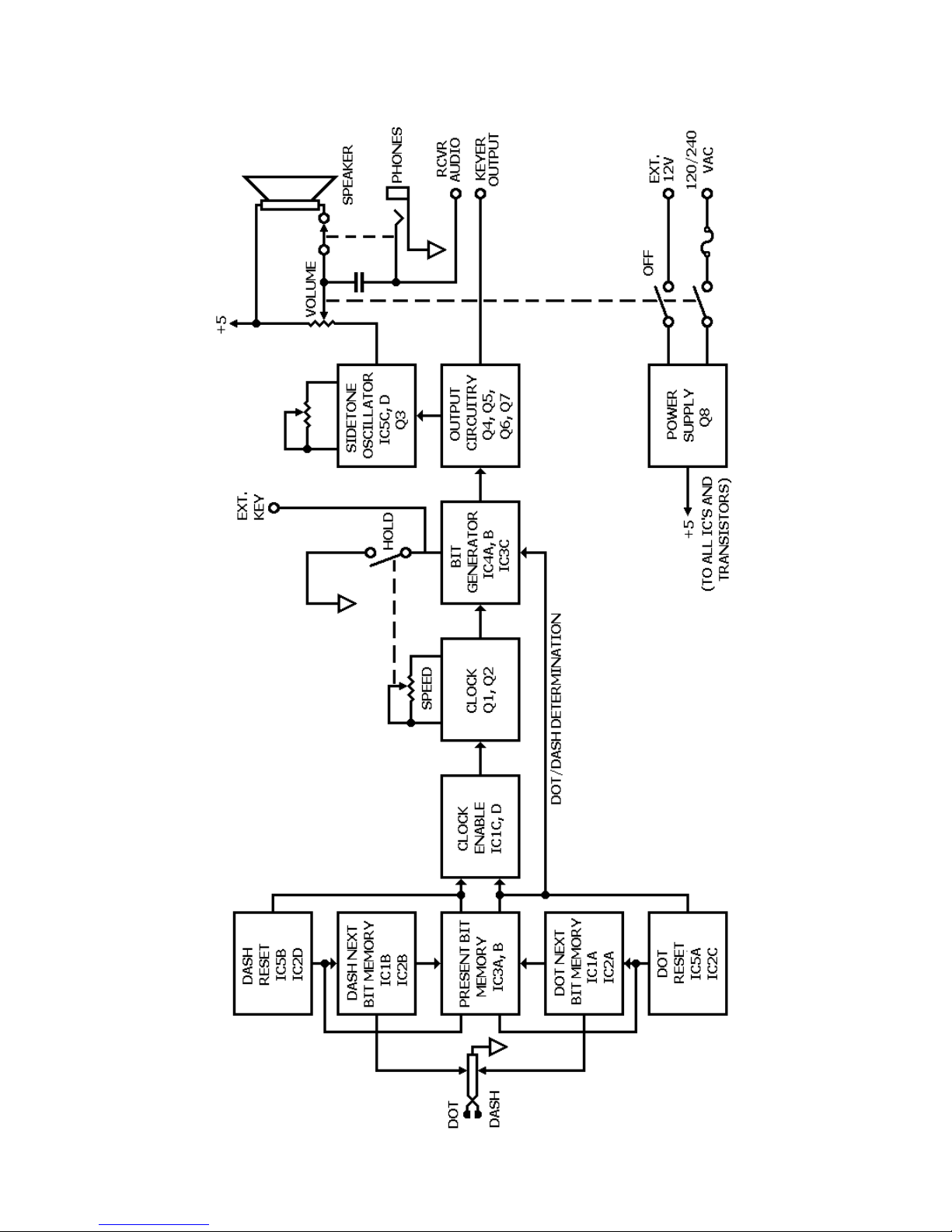
Refer to the Schematic Diagram and the Bloc Diagram while you read the following description.
To help you locate parts in the Keyer or on the Schematic, the resistors, capacitors and other com-
ponents are numbered in the following groups:
1 – 99 Parts mounted on the circuit board.
101 – 100 Parts mounted on the chassis.
The following terms and their definitions will be used during this description:
Mar : Key-down condition; IC3 pin 12 is high
Space: Key-up condition; IC3 pin 12 is low
Dot bit: Dot-mar and space following
Dash bit: Dash-mar and Space following
When you operate the paddles, the "present bit memory" commands the cloc enable circuit to
Start a bit and insures that the present bit is completed before another Starts. The "next bit mem-
ories" retain the information of which bit is next (a dot or dash), if a dot or dash was eyed before
the present bit is completed. After the present bit is completed, the "resets" load the "present bit
memory" with the information that is in the "next bit memories." Each dot, dash, and off time is
uniform because of the cloc which produces uniformly spaced pulses. The bit generator then re-
sponds to the cloc pulses and the dot/dash determining line to produce a dot (or a dash that is
three times longer than the dot) and an off time. The Output circuitry drives the eyer Output and
sidetone circuitry.
Because of the sequence of digital logic involved, the cloc will be explained first.
CLOCK
The cloc consists of transistors Q1, Q2, and their associated circuitry. When IC1 pin 8 is high the
cloc is disabled. Capacitor C3 charges through diode 01 and biases Q1 off. With Q1 off, the base
of Q2 is high. Therefore, Q2 is also off and the cloc output is low. Note that the high on IC1 pin 8
is also applied through D2 to IC4 pin 5. When IC1 pin 8 goes low (bit being sent), IC4A changes
state. D1 is then bac -biased and C3 begins to discharge through resistor R9, Speed control R101,
and resistor R11. When its voltage drops to the base Potential of Q1, Q1 begins to turn on, The
collector of Q1 and the base of Q2 begin to go less positive and turn on Q2. As Q2 turns on, its ris-
ing collector potential is coupled through capacitor C4 to the base of Ql and turns it on harder.
Thus the condition is regenerative and happens very quic ly.
The output is now high. This high on the collector of Q2 is applied to IC4 pin 5 by diode D3. C3
charges quic ly through resistor R7, the base-emitter junction of Q2 and Q1. C4 discharges and Q1
turns off, thus turning off Q2. This high-to-low transition on IC4 pin 5 again changes the state of
IC4A. Note that D2, D3 and resistor R12 form an "OR" gate and that IC4A changes state when IC1
pin 8 goes low (when the paddle is first eyed) and on the trailing edge of each cloc pulse.
BIT GENERATOR
The bit generator is composed of IC4A and B and IC3C. In the resting condition, IC4A and B are
reset (Q Outputs low). The highs on IC3 pins 1, 2, and 13 cause IC3 pin 12 to be low ( ey-up). If
IC4 pin 2 is low, IC4B cannot change state. The waveform in Figure 10 show how dots and dashes
are formed. Note that if IC4 pin 2 is low, dots are generated; if it is high, dashes are generated.

NEXT-BIT MEMORIES (NBM)
There are two "next-bit memories;" one for dots, composed of gates IC1A and IC2A and one for
dashes, composed of gates IC1B and IC2B. Each pair of gates is cross-coupled to form an R-S
(set-reset) flip-flop. Since their operation is similar, only the dash NBM will be discussed.
Figure 10
When no bit is being sent, 1C2 pin 8 is high since the cloc is tow. The dash NBM is in the reset
condition, with IC2 pin 6 high and IC1 pin 3 low. This low is applied to 1C3 pin 4. Therefore, IC3
pin 6 is high. (Similarly, IC3 pin 8 is also high.) When the dash paddle is eyed, IC1 pin 1 is
grounded momentarily through the paddle contacts. This causes IC1 pin 3 to go high. IC2 pins 4
and 5 are both high, so IC2 pin 6 goes low. This low is applied to IC1 pin 2 and holds IC1 pin 3
high after the paddle is released. IC3B now has a high on all three inputs, so pin 6 is low. This low
is applied to IC1 pin 13, and IC1 pin 11 goes high. IC1 pin 8 goes low, and the bit generator be-
gins to form a dash (since IC4 pin 2 is high).
PRESENT-BIT MEMORY (PBM)
Note that IC3A and B form an R-S flip-flop which, depending on its state, causes the bit generator
to form dots or dashes äs described in the section on the bit generator.
RESET CIRCUITRY
At the end of a bit, whether dot or dash, the PBM must assume the state of the next bit to be
sent. This is accomplished by the reset circuitry. IC5B, IC20, resistor R3 and capacitor C1 form the
dash reset circuit. (The dot reset circuitry is composed of IC5A, IC2C, resistor R4, and capacitor C2
operates the same). Iambic operation requires that if both paddles are closed, or if the dot paddle
is eyed during a dash bit, or the dash paddle is eyed during a dot bit, the next bit must be oppo-
site to that being sent.
Assume a dot is being sent. This means that IC3 pin 8 is low and IC3 pin 6 is high. This high is ap-
plied to IC5 pin 9 and holds IC5 pin 10 low. The trailing edge of the cloc pulse occurring at the
end of the dot bit mar ta es IC3 pin 12 low. At this time, IC5A has both inputs low, and IC5 pin
13 goes high. This enables IC2C for the next cloc pulse, which occurs at the end of the dot bit.

The leading edge of this cloc pulse ta es IC2 pin 11 low. This will reset the dot NBM unless the
dot paddle is still closed. If the dash paddle has not been closed, then there is a low on IC3 pin 4
which holds IC3 pin 6 high, and the PBM cannot change state. Thus the next bit will be another
dot. If, however, the dash paddle has been eyed sometime during the dot bit, then IC3 pin 4 will
be high. When IC2 pin 11 goes low, IC3 pin 10 goes low, and IC3 pin 8 goes high. Then IC3B has
all inputs high so IC3 pin 6 goes low and holds IC3 pin 8 high following the cloc pulse. On the
trailing edge of this cloc pulse, the bit generator begins a dash, since IC4 pin 2 is high.
A necessary delay is provided by R3 and C1. Recall that when the PBM changed state, IC3 pin 6
went low on the leading edge of the cloc pulse. IC3 pin 12 does not go high until the trailing
edge of the cloc pulse. Were it not for the delay, IC2 pins 9 and 10 would be high, and the low on
IC2 pin 8 would remove the dash from this memory if one were stored there.
OUTPUT CIRCUITRY
When IC3 pin 12 goes high (mar condition), it turns on the Darlington pair, transistors Q6 and Q7,
which will ey positive tines to ground. Transistor Q4 also turns on, thus turning on transistor Q5
and eying negative lines to ground through the power supply and resistor R25. Note that no more
than approximately 10 mA may be eyed by this circuit since it is a constant current sin which
limits at 10 mA. Diodes D4 and D5 isolate the two sections.
SIDETONE OSCILLATOR
The Sidetone Oscillator is made up of IC5 C and D, which are cross-coupled to form an astable
multivibrator. It is enabled when IC5 pin 6 goes low. Its Output is coupled to Q3, which drives the
spea er.
POWER SUPPLY
The Power Supply is a conventional series regulated bridge circuit that supplies +5 volts. Diode D6
protects the power supply against reversed battery polarity.

BLOCK DIAGRAM

CIRCUIT BOARD X-RAY VIEW
NOTE: To find the PART NUMBER of a component for the purpose of ordering a replacement:
A. Find the circuit component number (R15, C3 etc.) on the X-Ray View or "Chassis Photograph".
B. Locate this same number in the "Circuit Component Number" column of the "Parts List".
C. Adjacent to the circuit component number, you will find the PART NUMBER and DESCRIPTION
which must be supplied when you order a replacement part.
(Viewed from foil side)

(Viewed from component side)

CIRCUIT BOARD VOLTAGE CHART
(Viewed from foil side)

CHASSIS PHOTOGRAPH
MOD FROM "HINTS AND KINKS" TO CHANGE RANGE TO 8-35 WPM AND MAKE SPEED
CONTROL LESS CRITICAL:
PLACED 5k6 IN SERIES WITH R9; SHUNT SPEED CONTROL WITH 33k.

Other manuals for HD-1410
1
Table of contents
Other Heathkit Other manuals
Popular Other manuals by other brands

RFIDeas
RFIDeas pcProx Plus user manual

Aqua Medic
Aqua Medic aquafit Operation manual

Silvercrest
Silvercrest 289362 Operation and safety notes

Alfalaval
Alfalaval Toftejorg SaniMicro instruction manual

Air Lift
Air Lift 75557 installation guide

Speed Clean
Speed Clean CoilJet CJ-200E Operating & maintenance instructions