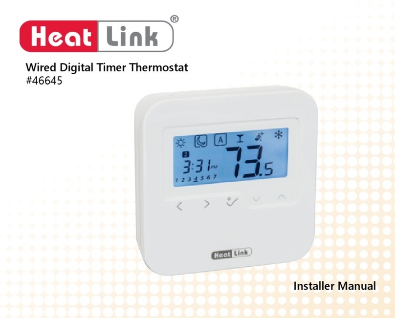
HeatLink 46544 User manual

®
Heat Link
www.heatlinkgroup.com
Toll Free: 1-800-661-5332
Canada Fax: 1-866-450-1155
USA Fax: 1-800-869-6098
©2013 HeatLink Group Inc.
L646544U
2013-01-08
#46544 Digital Thermostat
User Guide - Page 1 of 4
Parameter Number
Parameter Menu
Temperature Unit
Type of Sensor Used and
Temperature Displayed
(see legend below)
Regulation = Internal or external ambient sensor.
Regulation = Floor sensor.
Regulation = Internal sensor with floor limitation.
View of the external sensor temperature.
Plus Button
Lock Indicator
Cooling Demand Indicator
Heat Demand Indicator
COMFORT MODE
AUTO-SETBACK MODE
SETBACK MODE
FREEZE PROTECTION MODE
TIMER MODE
OFF MODE
Left Button
Minus Button
Back Button
Right Button
Edition Button
OK Button and Status LED
Status LED
Solid Red (when backlight is lit up) = heating demand
Solid Green (when backlight is lit up) = cooling demand
Flashing Red = sensor error
Flashing Green = waiting for input
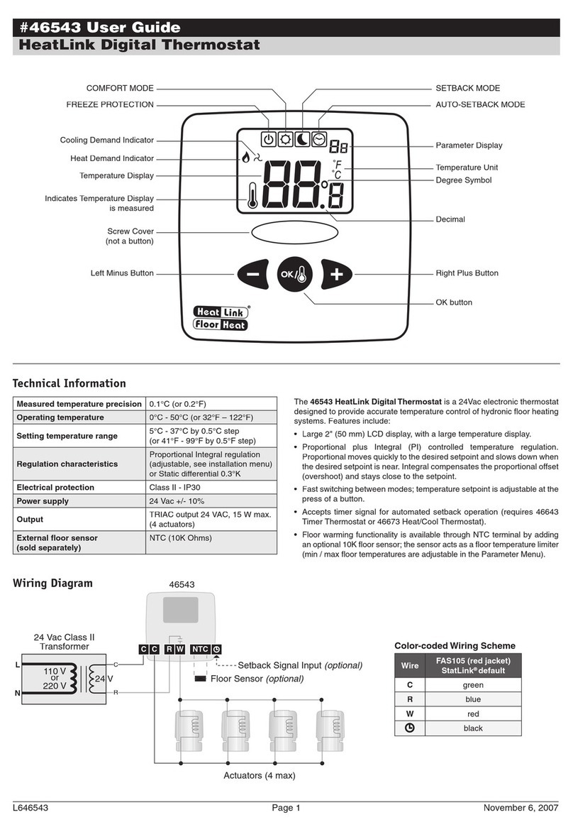
The 46544 HeatLink Digital Thermostat is a 24Vac electronic
thermostat designed to provide accurate temperature control of hydronic
floor heating systems. Features include:
• Large 2" (50 mm) backlit LCD display, with a large temperature display.
• Proportional plus Integral (PI) controlled temperature regulation.
Proportional moves quickly to the desired setpoint and slows
down when the desired setpoint is near. Integral compensates the
proportional offset (overshoot) and stays close to the setpoint.
Output signal is either Pulse Width Modulation (PWM) or Hysteresis
(on/off).
• Fast switching between modes; temperature setpoint is adjustable at
the press of a button.
• Accepts timer signal for automated setback operation (requires 46643
Timer Thermostat or 46673 Heat/Cool Thermostat).
• Floor warming functionality is available through NTC terminal by adding
an optional 10K floor sensor; the sensor acts as a floor temperature
limiter (min / max floor temperatures are adjustable in the Parameter
Menu).
Technical Information
Measured temperature precision 0.1°C (or 0.2°F)
Operating temperature 0 to 40°C (or 32 to 104°F)
Setting temperature range 5 to 37°C by 0.5°C step
(or 41 to 99°F by 0.5°F step)
Regulation characteristics
Proportional Integral regulation or
Static differential
(see Installer Parameters
L646544N)
Electrical protection Class II - IP30
Power supply 24 Vac +/- 10%
Output TRIAC output 24 VAC, 15 W max.
(4 actuators)
External sensor
(sold separately)
NTC (10K Ohms)

®
Heat Link
www.heatlinkgroup.com
Toll Free: 1-800-661-5332
Canada Fax: 1-866-450-1155
USA Fax: 1-800-869-6098
©2013 HeatLink Group Inc.
L646544U
2013-01-08
#46544 Digital Thermostat
User Guide - Page 2 of 4
Installation
➀Loosen the Wiring Terminals screws, connect the wires to each of the
terminals as per the wiring diagram, and tighten the screws.
The terminal block can be removed to make wiring connections easier.
➁Open the side panels to expose the screw holes.
➂Mount the thermostat using the supplied screws.
➃Close the side panels.
Mounting Location
• Mount the thermostat at 5' (1.5 m) from the floor
• Mount on inner walls only, and at least 2' (0.6 m) away from any outer wall. Avoid entrances.
• Mount away from any direct heat sources like: air vents, radiators, and lights.
• Avoid Moisture, it is damaging to electronics, so avoid installing in areas that would contain high humidity or condensation (e.g. bathrooms or
greenhouses).
• Do not cover or enclose, allow for proper air circulation, to get a good measurement of the current air temperature.
C RW NTC
Actuators (4 max)
C
24 Vac Class II
Transformer
L
N
24 V
110 V
or
220 V
External Sensor (optional)
Setback Signal Input (optional)
46544
R
Color-coded Wiring Scheme
Wire FAS105 (red jacket)
StatLink® default
Cgreen
Rblue
Wred
black
Wiring Diagram
2.36" (60 mm)

®
Heat Link
www.heatlinkgroup.com
Toll Free: 1-800-661-5332
Canada Fax: 1-866-450-1155
USA Fax: 1-800-869-6098
©2013 HeatLink Group Inc.
L646544U
2013-01-08
#46544 Digital Thermostat
User Guide - Page 3 of 4
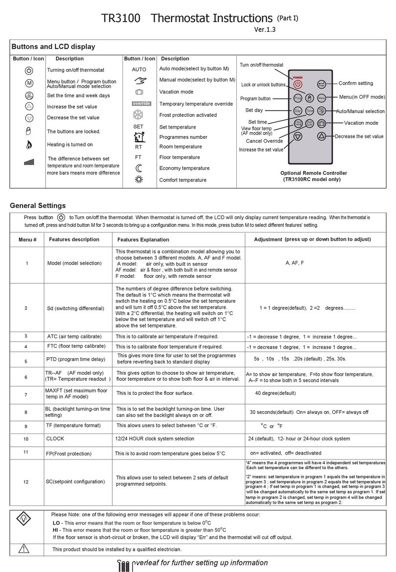
Lock Function
Use this function to prevent changing of the settings.
To activate the lock function:
1. Press and hold the “back” button, then press the
“edition” button.
2. The Lock Indicator will be shown.
To deactive the lock function:
1. Press and hold the “back” button, then press the
“edition” button.
2. The Lock Indicator will be disappear.
Information Function
Use this function to quickly view all current temperatures.
This function is available in all modes.
Repeatedly press the “back” button to “scroll” between
the current setpoint, measured ambient temperature, and
floor temperature (if floor sensor is connected).
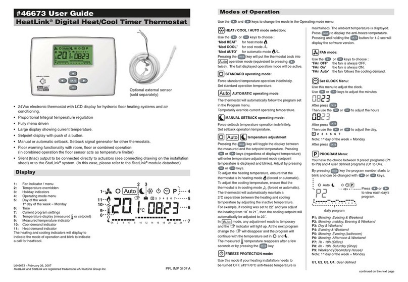
PRESS OR to cycle through the modes.
User Operation
In all modes, if a floor sensor is installed, blinking indicates that
the floor temperature is outside the limits set by the FL.L and FL.H
parameters.
Auto-setback mode
(Requires a timer setback signal)
In auto-setback mode, the 46544 operates automatically between
comfort mode ( blinking) and setback mode ( blinking)
according to the schedule of a timer thermostat (46643 or 46673).
Comfort mode (Default)
In comfort setpoint mode, the temperature is set to a comfortable level,
the default is 21°C (70°F). This mode is ideal for occupied areas. To
change the comfort setpoint temperature (while in comfort mode):
PRESS OR The Current Setpoint Temperature will
blink and can be changed.
After 5 seconds the setpoint will be set and the measured temperature
will return.
Freeze Protection mode
In Freeze Protection mode: instead of simply turning the system off,
this thermostat prevents freezing by maintaining a user adjustable
fixed temperature (see user parameter 06 “HG”).
This mode is ideal for unoccupied buildings (e.g. holidays).
Off mode
Use this mode in case you need to switch off your system.
When the display is off, press the “OK” button to display the current
temperature for a few seconds.
To restart your system, select a different mode.
Warning: Use this mode with caution, your system can freeze.
Setback mode
In setback mode, the temperature is set lower to conserve energy, the
default is 17°C (63°F). This mode is ideal for areas that are unoccupied.
To change the setback temperature (while in setback mode):
PRESS OR The Current Setpoint Temperature will
blink and can be changed.
After 5 seconds the setpoint will be set and the measured
temperature will return.
Timer mode
The Timer mode allows you to adjust the temperature for a set
period of time without changing your normal settings.
PRESS OR The Current Setpoint Temperature will
blink and can be changed.
PRESS This will change to the Duration
setting.
PRESS OR The Duration will blink and can be
changed.
The icon will blink and the number of hours/days remaining is shown
until the end of the period.
At the end of the period the thermostat will automatically change to
Comfort mode.
If you want to stop the Timer function early, change the duration to
“no”.

®
Heat Link
www.heatlinkgroup.com
Toll Free: 1-800-661-5332
Canada Fax: 1-866-450-1155
USA Fax: 1-800-869-6098
©2013 HeatLink Group Inc.
L646544U
2013-01-08
#46544 Digital Thermostat
User Guide - Page 4 of 4
User Parameter Menu
Exiting the User Parameter Menu
• After 30 seconds of inactivity the thermostat will automatically exit the
menu.
• Press the “back” button.
• Use the “left” or “right” buttons to navigate to parameter 10
and press the “OK” button.
Parameter Description Range Default
01 dEG Select the temperature unit. “°C” = Celsius
“°F” = Fahrenheit
“°C”
04 Internal sensor calibration; displays measured temperature. Adjust to show
“actual” internal sensor temperature.
The calibration should only be done after 1 day of system operation with the
same set temperature as follows:
Put a thermometer in the room at the same height as the thermostat and
check the thermometer temperature in the room after 1 hour.
When you enter the calibration parameter "no" is displayed to indicate no
calibration has been made.
Enter the thermometer temperature using the “minus” or “plus” buttons. The
message "YES" should be displayed; the value will be stored in the internal
memory.
If you need to erase a calibration press the “back” button. The old value will
be erased and the message “no” will be displayed.
Note: Only the heating controlled by the thermostat must be used during
calibration.
“no” = no calibration
“YES” = calibration applied
5.0 to 37.0°C
41°F to 99.0°F
“no”
05 External sensor calibration; displays measured temperature. Adjust to show
“actual” external sensor temperature. If no sensor is detected, no adjustment
can be made.
Follow the calibration prodedure as described in parameter 04.
“no” = no calibration
“YES” = calibration applied
5.0 to 37.0°C
41°F to 99.0°F
“no”
06 HG Freeze protection setpoint. 0.5 to 10.0°C
33°F to 50.0°F
10°C
50°F
08 CLr Resets all parameters to factory defaults.
PRESS & HOLD “OK” Button for 5 seconds to reset all installer parameters.
09 Displays the firmware version.
10 End Exits the user parameter menu.
To access the Installer Parameter Menu:
1. In any thermostat mode, press and hold the “edition” button for 10s.
2. Press the “left” or “right” buttons to cycle through the
parameters.
To see or adjust a parameter value:
1. Press the “OK” button.
2. Use the “minus” or “plus” buttons to adjust parameter value.
3. Press the “OK” button to set the adjustment.
Table of contents
Other HeatLink Thermostat manuals
Popular Thermostat manuals by other brands
Pro 1 IAQ
Pro 1 IAQ T605-2 operating manual
Fantini Cosmi
Fantini Cosmi KIT CH130ARR2 Instructions for use
Pro 1 IAQ
Pro 1 IAQ TRUE COMFORT III T605-2 installation manual
System air
System air S-27989 Instruction
smart home
smart home TempLinc INSTEON 2441ZTH owner's manual
CORAB
CORAB TSTPHA01 installation instructions
Pro 1 IAQ
Pro 1 IAQ T601-2 installation manual
Pro 1 IAQ
Pro 1 IAQ T631W-2 installation manual

Environmental Technologies
Environmental Technologies SST-2 Installation and operation manual

Nu-Heat
Nu-Heat SOLO user guide

eControls
eControls Comfort 365 C365T11 Installer manual

Pro 1 IAQ
Pro 1 IAQ T755 installation manual
