eControls Comfort 365 C365T11 User guide

Inside
Tu
Day
Upstairs
Auto
Downstairs
Airflow %
HEAT
Schedule
AUTO
FANMENU MODE
Heat
Set To
SYSTEM
AM
365
Comfort
UP/DOWN Keys.
SYSTEM MODE Key
OFF, HEAT, COOL or Auto
Displays the downstairs
(Inside) or upstairs (Inside2)
temperature.
Displays the Thermostat Mode
HOLD, SCHEDULE or VACANT
Displays the time, day and schedule
MORNING, DAYTIME, EVENING
or NIGHT
MENU Key Displays
the User options.
MODE Key Selects
Thermostat Mode
HOLD, SCHEDULE or VACANT
Displays the upstairs airflow
Displays the Airflow Mode
AUTOMATIC or MANUAL
Displays the heating or
cooling temperature
FAN MODE Key
AUTO or ON
Description
System Modes
Airflow Limits
Nighttime Operation
Upstairs Temperature Sensor
Modulating Dampers
Power
Warranty
Compatible HVAC Equipment
Thermostat Modes
Programs per Day
Program Format
Temperature Override
Airflow Override
Airflow Modes
Fan Modes
The C365 thermostat controls the heating and cooling system
the same as most programmable thermostats. It also controls
the airflow to the upstairs and downstairs using an upstairs and
a downstairs modulating damper. A temperature sensor
located upstairs monitors the upstairs temperature and the
temperature sensor in the C365 monitors the downstairs
temperature.
The C365 adjusts the upstairs and downstairs airflow during
heating and cooling calls to maintain uniform upstairs and
downstairs temperatures.
Off, Heating only, Cooling only, Automatic Heating or Cooling.
Maximum upstairs and downstairs, heating and cooling airflow
limits are set during installation.
Option used when bedrooms are located upstairs. C365 uses
the upstairs temperature sensor to control heating and cooling
calls and directs more airflow upstairs.
One Model TS5-10 or two Model TS5-20 upstairs temperature
sensors can be used.
Round or rectangular dampers using the A80MOC actuator
and up to 1 inch static pressure.
Operates on 24VAC from the HVAC equipment using the R
and C wires.
Single stage gas or electric heating with single stage
compressor.
Hold, Schedule or Vacant mode.
Morning, Daytime, Evening and Night.
Weekdays and weekend– 5/2.
Up/down keys adjust the setpoint temperature. Temperature
setting is held for 4 hours when adjusted in Schedule mode.
Up/down keys adjust the upstairs/downstairs airflow. Airflow
setting is held for 4 hours when adjusted in Automatic mode.
Automatic or Manual when Manual mode is enabled.
Continuous or Automatic fan operation.
This thermostat is warranted to be free of defects due to
workmanship or materials under normal use and service for a
period of 5 years from date of installation and not longer than
6 years from manufacturing date code.
Installer Manual
Model C365T11
365
Comfort
eControls, Inc. 26072 Merit Circle #110 / Laguna Hills, CA 92653
949-916-0945 Fax 949-458-8502 www.eControlsUSA.com
eControlseControls
Rev A Jan 2016
Displays the downstairs airflow
NEXT Key
Used to advance through
options
ENTER Key
Used to save options and
return to thermostat operation
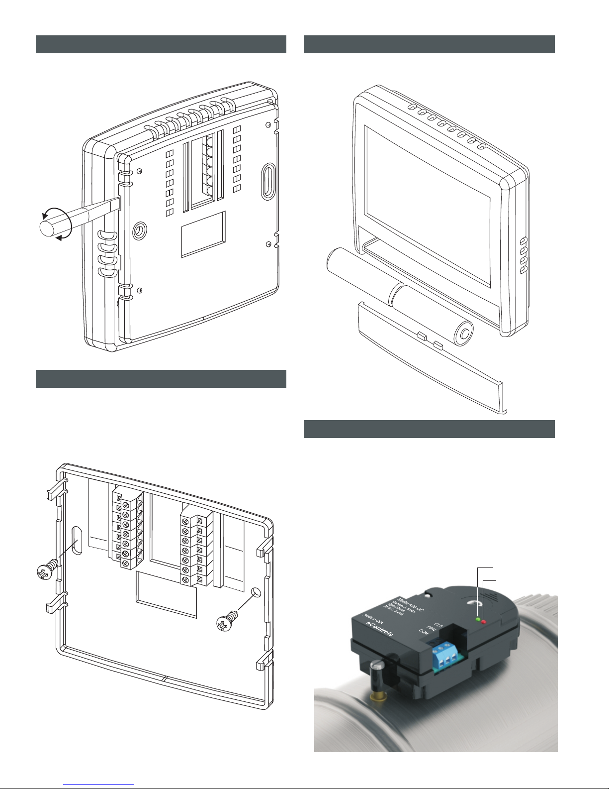
SEPARATE THE C365 SUBBASE
ATTACH THE SUBBASE TO THE WALL
INSTALL TWO AA BATTERIES
Place a slotted screwdiriver in the slots as shown and rotate to
remove subbase from the C365 housing.
Attach the subbase to an interior wall and about 5-feet above
the floor as shown using the screws and wall anchors supplied.
The wires to the dampers, HVAC equipment and the upstairs
temperature sensor pass through the opening between the
terminals.
The batteries power the clock when 24VAC power is lost. Slide
the battery cover downward and install the two AA batteries as
shown.
R
C
W
EQUIPMENT
Y
G
Upstairs
Sensor
COM
COM
CLS
CLS
OPN
OPN
Upstairs
Downstairs
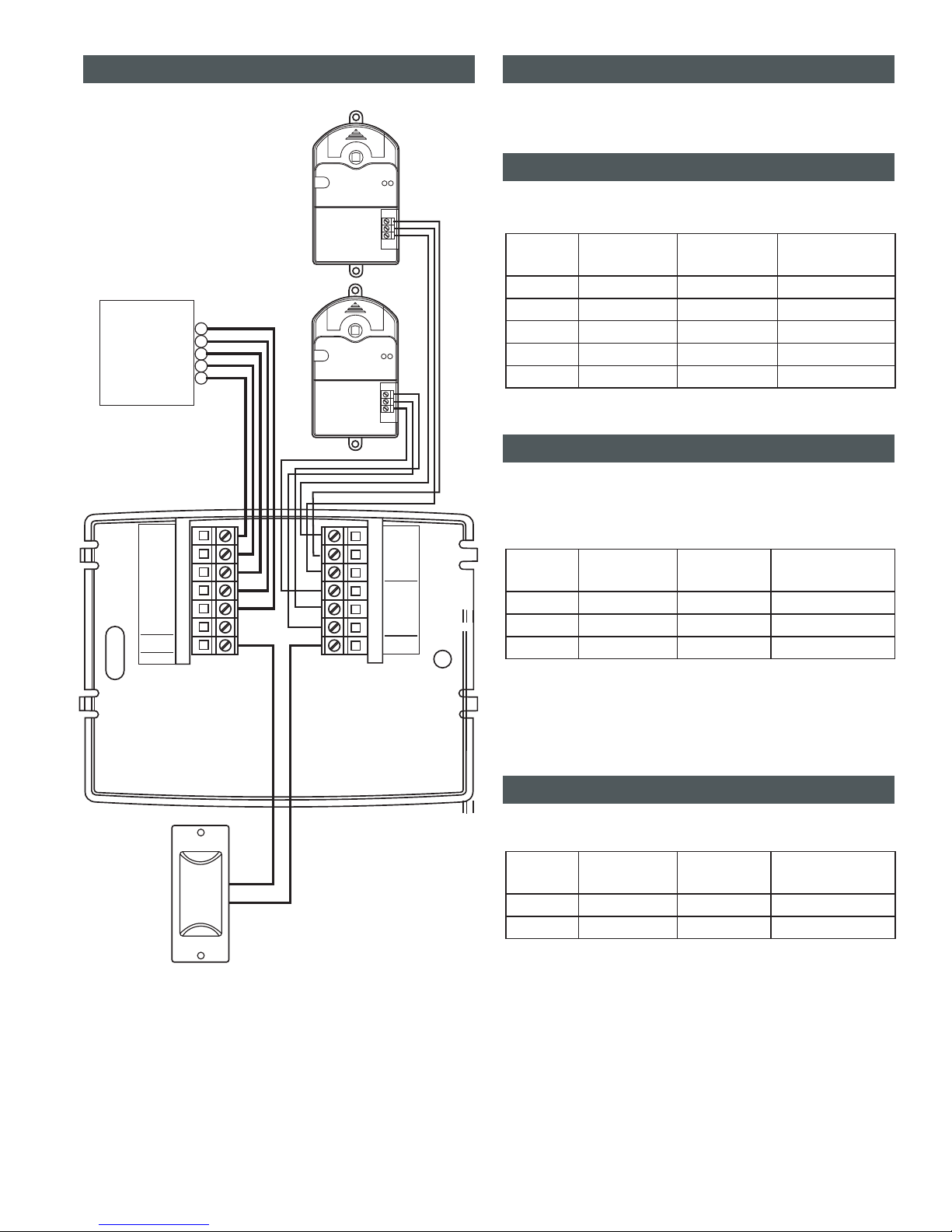
Install an R80CT damper in the duct supplying air to the upstairs
and wire the terminals to the corresponding terminals on the
C365T. Install a second R80CT damper in the duct supplying air
to the downstairs and wire it to the C365T. Each damper uses
2.4VA of power.
When two or more dampers are required to define the upstairs or
downstairs zones, the damper may be wired in parallel. LEDS
on the damper actuator indicate when the damper is fully open
(green) or fully closed (red).
Green LED
Red LED
INSTALL UPSTAIRS & DOWNSTAIRS DAMPERS
2
Upstairs
Sensor
RCOM
CLS
OPN
COM
CLS
OPN
C
W
EQUIPMENT
UpstairsDownstairs
Y
G
Upstairs
Sensor
Model A80-MOC
Damper Actuator
Modulating or
Open/Close
24VAC,2.4VA COM
OPN
CLS
Made in USA
eControls, Inc.
Model A80-MOC
Damper Actuator
Modulating or
Open/Close
24VAC,2.4VA COM
OPN
CLS
Made in USA
eControls, Inc.
G
HVAC System
Model R80CT-XX
Upstairs Damper
Model C365T11
Downstairs Thermostat
Model TS5
Upstairs
Temperature
Sensor
Model R80CT-XX
Downstairs Damper
Y
W
C
R
WIRING DIAGRAM WIRING INSTRUCTIONS
Equipment Wiring
Warning!
Damper Wiring
Upstairs Temperature Sensor Wiring
Use 5-conductor, 18 or 20 gage, thermostat cable to wire from
the C365 Thermostat to the equipment.
Turn the power to the HVAC equipment off before wiring.
Use 3-conductor, 18 or 20 gage, thermostat cable to wire from
the C365 Thermostat to the upstairs and downstairs dampers.
There are separate terminals for the upstairs and the
downstairs dampers.
Multiple dampers can be used to construct the upstairs or
downstairs zones. Daisy chain terminals– COM to COM, OPN
to OPN and CLS to CLS.
Use 2-conductor, 18 or 20 gage, thermostat cable to wire from
the C365 Thermostat to the upstairs temperature sensor.
C365
Terminal
C365
Terminal
C365
Terminal
R
COM
SNR
C
CLS
SNR
W
OPN
Y
G
Wire Color
Wire Color
Wire Color
Red
White
White
Blue
Red
Red
White
Green
Yellow
Green
Equipment
Terminal
Damper
Terminal
Sensor
Terminal
R, Rc, Rh
COM
SNR
C
CLS
SNR
W, W1
OPN
Y, Y1
G
Function
Function
Function
24VAC Power
Common
Thermistor
Common
Closes damper
Thermistor
Heating
Opens damper
Fan
Cooling
For single temperature sensor application, use Model TS5-10.
Two temperature sensors can be installed in different areas
upstairs and the two temperatures will be averaged. For dual
sensor applications, use Model TS5-20 and daisy chain the
sensors.
3
C365T11
Upstairs
Sensor
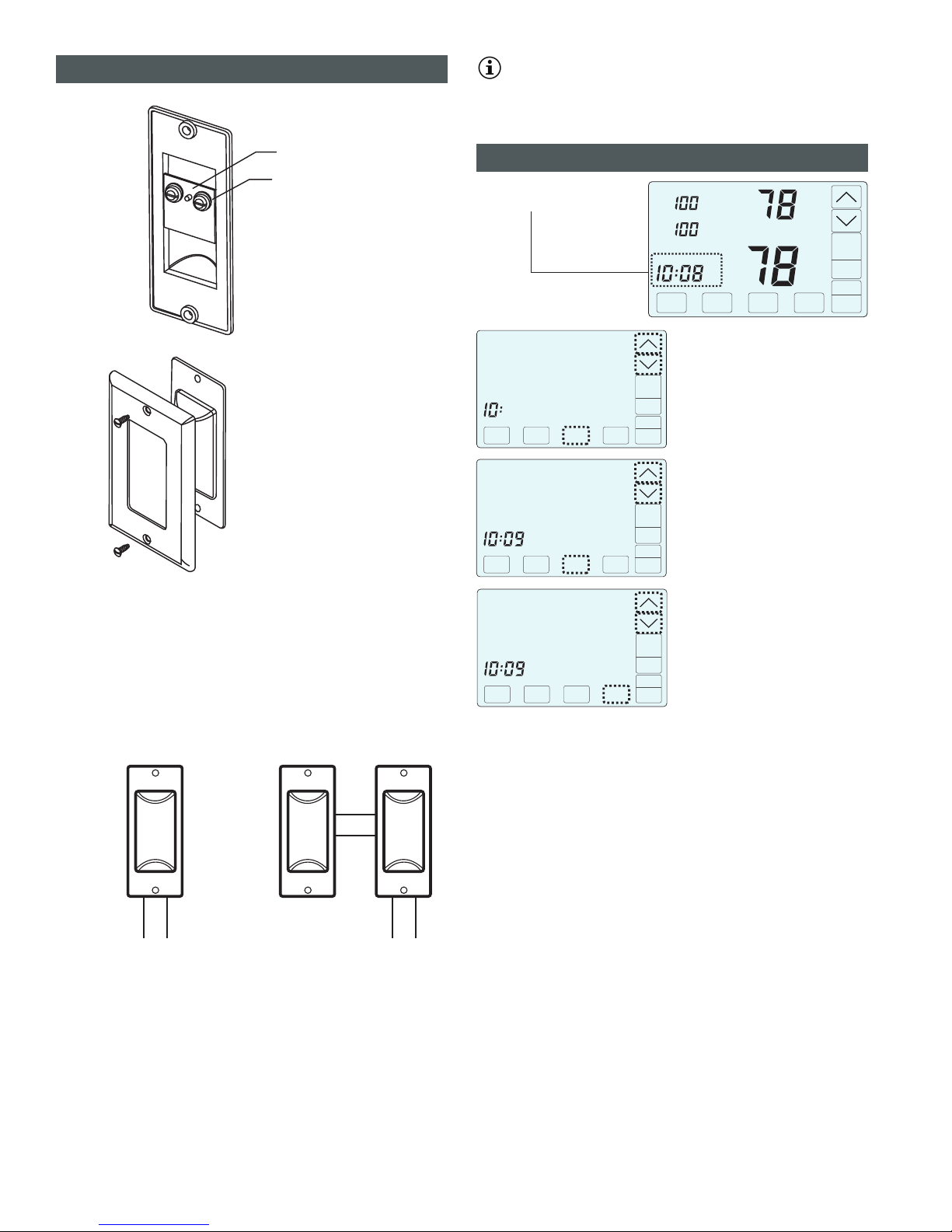
Upstairs Temperature Sensor Wiring (Cont)
Single Upstairs
Temperature Sensor
Dual Upstairs
Temperature Sensors
Place wire between brass
washer and the printed circuit
board and hand tighten screw.
The TS5 can be installed in a
single gang box or directly to
the wall using the hardware
provided.
HAND
TIGHTEN
Printed circuit board
Brass washer
Model TS5-10
Upstairs
Temperature
Sensor
Model TS5-20
Upstairs
Temperature
Sensor
Model TS5-20
Upstairs
Temperature
Sensor
Wire to
the C365T11
Wire to
the C365T11
4
Set Time and Day
NEXT ENTER
AM
Touch the UP/DOWN keys to change the
HOUR. Touch NEXT to save the hour and
go to change the minute.
CHANGE THE HOUR
Touch the UP/DOWN keys to change the
MINUTE. Touch NEXT to save the minute
and go to change the day of the week.
CHANGE THE MINUTE
Touch the UP/DOWN keys to change the
DAY OF THE WEEK.
Touch ENTER to save the day fo the
week and return to thermostat operation.
CHANGE THE DAY OF THE WEEK
Inside
Tu
Day
Upstairs
Auto
Downstairs
Airflow %
COOL
Schedule
AUTO
FANMENU MODE
Cool
Set To
SYSTEM
AM
Touch here to change the
time and day of the week.
We
ENTER
AM
NEXT ENTER
AM
Press the touchscreen with your fingertip
only, using a firm touch. Do not use a
sharp object such as a pen or pencil.
Option
01
02
03
04
05
06
07
08
09
10
12
13
14
15
16
17
19
18
20
21
Description
Compressor Stages
Heating Stages.
Fan Operation.
Compressor Minimum Off Time (minutes).
Gas Minimum Off Time (minutes).
Minimum Run Time (minutes).
On-Off Temperature Differential
Smart Recovery.
Vacant Heating Setpoint.
Vacant Cooling Setpoint.
Night Level LCD Backlight
Airflow Control On or Off
Enable Selecting Manual Airflow Control.
Maximum Upstairs Airflow in Heating.
Maximum Downstairs Airflow in Heating.
Maximum Upstairs Airflow in Cooling.
Maximum Downstairs Airflow in Cooling.
Maximum Temperature Difference Between
Upstairs and Downstairs.
Factory Restore
0 Cooling On 1 above setpoint, Off at setpoint. Heating On1 below setpoint, Off at setpoint.
o o
1 Cooling On 1 above setpoint, Off .5 below setpoint. Heating On1 below setpoint, Off .5 above setpoint.
o o o o
2 Cooling On 1 above setpoint, Off 1 below setpoint. Heating On1 below setpoint, Off 1 above setpoint.
o o o o
Display
Cpr
+ Heat
+ Cool
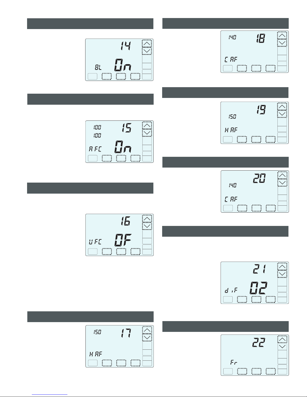
BL
AFC
UFC
HAF+Heat
HAF+Heat
CAF+Cool
CAF+Cool
diF
Fr
Htg
Fan
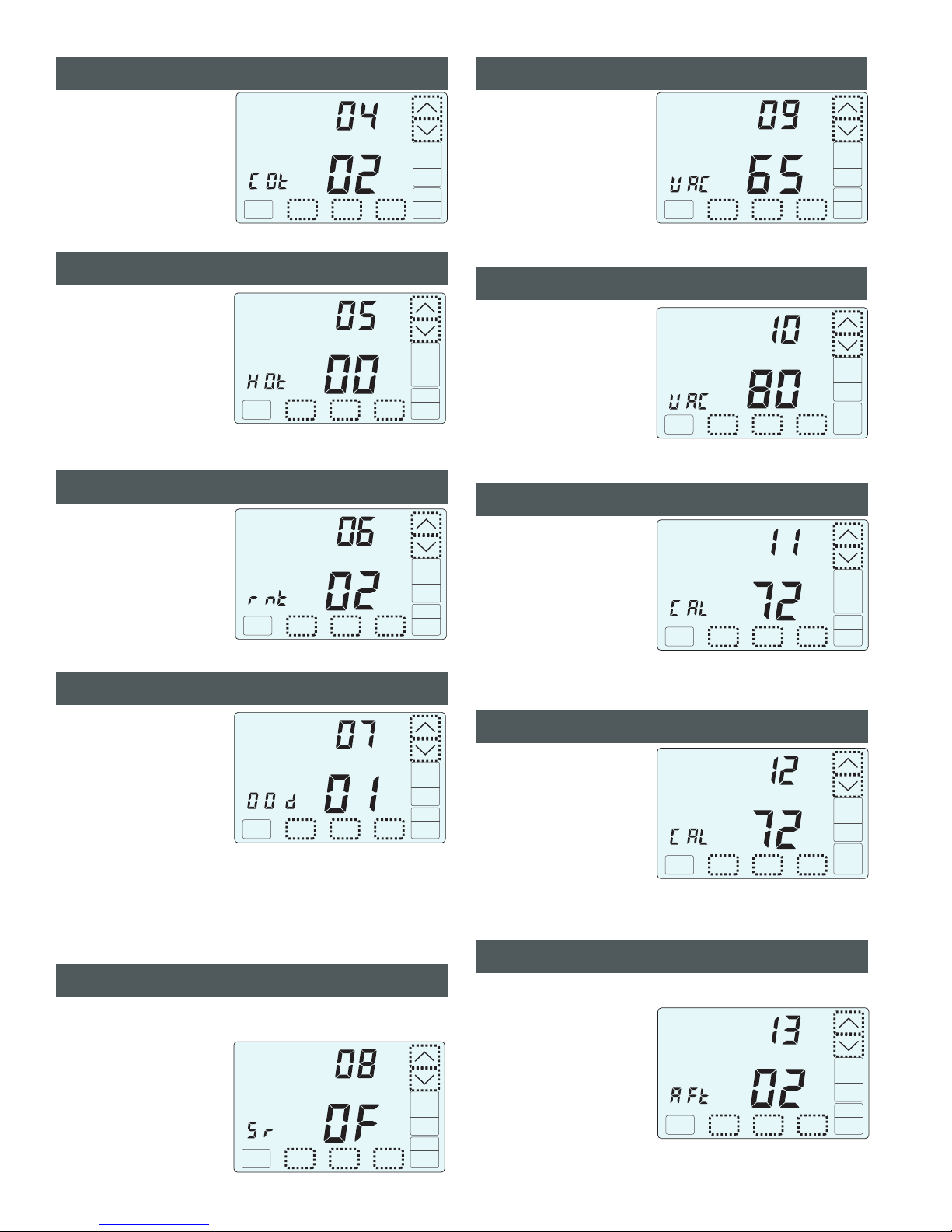
Cot
HOt
OOo
S r
V A C
V A C
Range
0 or 1
0 or 1
GA(Up) or EL(Down)
0 to 9
0 to 9
0, 1 or 2
0n(Up) or Off(Down)
44 to 75
74 to 95
On(Up) or Off(Down)
On(Up) or Off(Down)
On(Up) or Off(Down)
100 to 160%
100 to 160%
100 to 160%
100 to 160%
0 to 10
No(Next) or Yes(Enter)
Default
1
1
GA
2
0
1
Off
65
80
On
On
Off
150%
150%
140%
140%
2
NA
+ Night
INSTALLER OPTIONS
r n t 0 to 9 2
11 Calibrate Downstairs Sensor C A L +/- 5 0
Airflow Update Time A F t 1 to 20 minutes 2
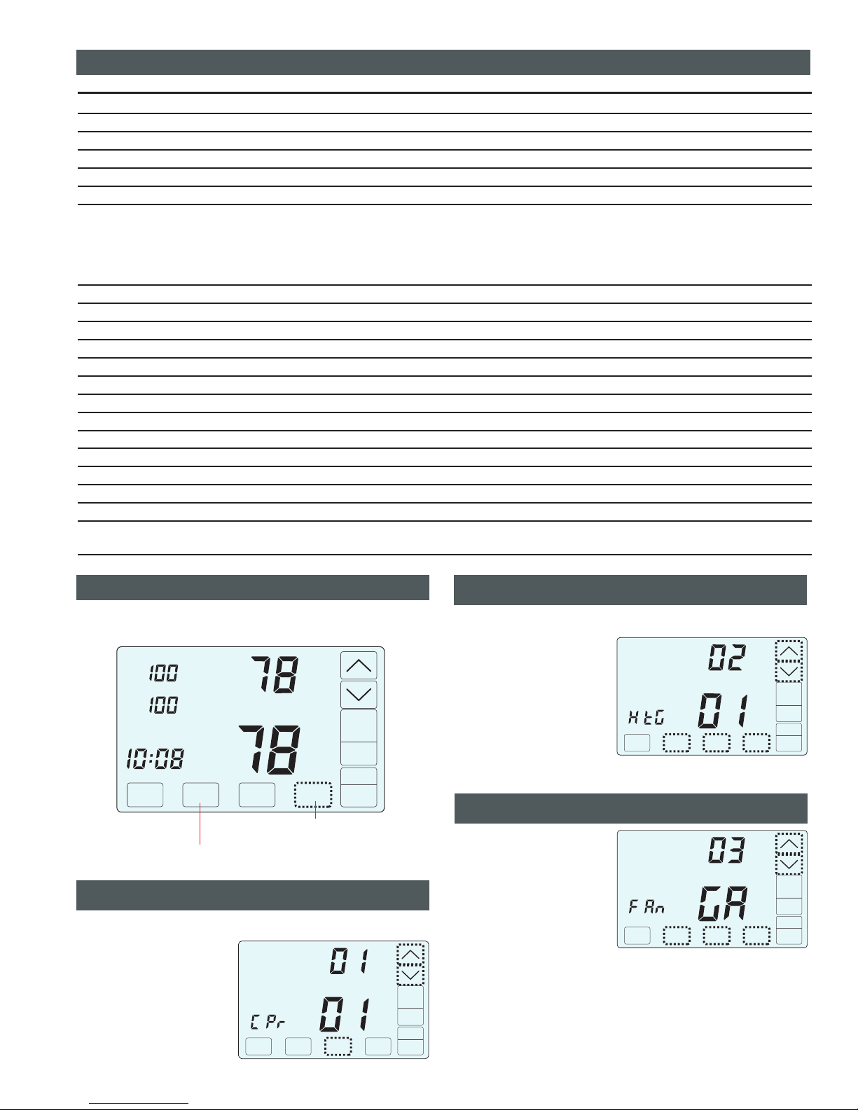
ACCESSING INSTALLER OPTIONS
To access the Installer Options, and the hidden Enter
key for 7 seconds until the first Option appears on the screen.
TOUCH HOLD
Inside
Tu
Day
Upstairs
Auto
Downstairs
Airflow %
COOL
Schedule
AUTO
FANMENU MODE
Cool
Set To
SYSTEM
AM
TOUCH HOLD and this key for 7 seconds
to access the Installer Options.
Touch the keys to
set 0 or 1 stage.
Touch to display the
next option. After about 20
seconds, the installer options
will time out and return to
normal thermostat operation.
UP/DOWN
NEXT
Option
NEXT ENTER
01 Setting the Compressor Stages
This option is used to set the number of cooling stages.
Option
NEXT ENTER
Touch the keys to
set 0 or 1 stage.
Touch to display the
next option, or to save
the option and return to normal
thermostat operation, or touch
the hidden key to return
to the previous option.
UP/DOWN
NEXT
ENTER
BACK
This option is used to set the number of heating stages.
Option
NEXT ENTER
Touch the key to select
“EL” for electric operation
where the thermostat activates
the indoor fan (G terminal)
during heating calls or
key to select GA for gas
operation where the equipment
plenum sensor activates the
indoor fan in heating calls.
Touch to display the
next option, or to save
the option and return to normal
thermostat operation.
UP
DOWN
NEXT
ENTER
5
22
Calibrate Upstairs Sensor. C A L +/- 5 0
Factory Default: 1 Stage. Range: 0 or 1
02 Setting the Heating Stages
Factory Default: 1 Stage. Range: 0 or 1
03 Setting the Fan Operation in Heating
Factory Default: Gas. Range: GA or EL
The hidden BACK key can be
used to return to previous options.
6
Touch the keys to
change the minimum off time
(minutes) before restarting the
compressor.
Touch to display the
next option, or to save
the option and return to normal
thermostat operation.
UP/DOWN
NEXT
ENTER
Option
NEXT ENTER
Option
NEXT ENTER
Touch the keys to
change the minimum run time
(minutes) before turning a
system off.
Touch to display the
next option, or to save
the option and return to normal
thermostat operation.
UP/DOWN
NEXT
ENTER
Option
NEXT ENTER
Touch the keys to
change the minimum off time
(minutes) before restarting a
gas furnace or electric strip
heater.
Touch to display the
next option, or to save
the option and return to normal
thermostat operation.
UP/DOWN
NEXT
ENTER
Touch the keys to
select 0, 1, 2.
Touch to display the
next option, or to save
the option and return to normal
thermostat operation, or touch
the hidden key to return
to the previous option.
UP/DOWN
NEXT
ENTER
BACK
Option
NEXT ENTER
0
1
2
o
Turns cooling On 1 above setpoint and Off at Setpoint.
o o
Turns cooling On 1 above setpoint, Off .5 below Setpoint.
Turns cooling On 1 above setpoint, Off 1 below Setpoint.
o o
Turns heating On 1 below setpoint and Off at Setpoint.
o
o o
Turns heating On 1 below setpoint, Off .5 above Setpoint.
o o
Turns heating On 1 below setpoint, Off 1 above Setpoint .
Touch the key to select ON
to turn on smart recovery or
touch the key to select
OF to turn smart recovery off.
Touch to display the
next option, or to save
the option and return to normal
thermostat operation.
UP
DOWN
NEXT
ENTER
Smart recovery initiates a heating or cooling call so that the space is
at temperature when the setback period ends.
Option
NEXT ENTER
Touch the keys to
select the heating temperature
when the space is vacant.
Touch to display the
next option, or to save
the option and return to normal
thermostat operation, or touch
the hidden key to return
to the previous option.
UP/DOWN
NEXT
ENTER
BACK
Option
NEXT ENTER
Touch the keys to
select the cooling temperature
when the space is vacant.
Touch to display the
next option, or to save
the option and return to normal
thermostat operation, or touch
the hidden key to return
to the previous option.
UP/DOWN
NEXT
ENTER
BACK
Option
NEXT ENTER
Cool
Vacant
Vacant
Touch the keys to
change the downstairs (Inside)
temperature to the temperature
that the user feels is correct.
Touch to display the
next option, or to save
the option and return to normal
thermostat operation, or touch
the hidden key to return
to the previous option.
UP/DOWN
NEXT
ENTER
BACK
Inside
Option
NEXT ENTER
Heat
Touch the UP/DOWN keys to
change the upstairs (Inside2)
temperature to the temperature
that the user feels is correct.
Touch NEXT to display the
next option, or ENTER to save
the option and return to normal
thermostat operation, or touch
the hidden BACK key to return
to the previous option.
Inside2
Option
NEXT ENTER
Touch the keys to
set the time in minutes to
update the upstairs and
downstairs airflow.
Touch to display the
next option, or to save
the option and return to normal
thermostat operation, or touch
the hidden key to return
to the previous option.
UP/DOWN
NEXT
ENTER
BACK
Option
NEXT ENTER
This is the frequency, in minutes, that the damper position is updated.
04 Compressor Minimum Off Time
Factory Default: 2 Minutes. Range: 0 to 9 Minutes
05 Heating Minimum Off Time
Factory Default: 0 Minutes. Range: 0 to 9 Minutes
06 Minimum Run Time
Factory Default: 2 Minutes. Range: 0 to 9 Minutes
10 Vacant Cooling Setpoint
o o
Range: 74 F to 95 F
o
Factory Default: 80 F.
09 Vacant Heating Setpoint
o o
Range: 44 F to 75 F
o
Factory Default: 65 F.
07 Setting On-Off Temp Differential
Factory Default: #1. Range: 0, 1 or 2.
08 Smart Recovery
Factory Default: Off. Range: On or Off.
11 Calibrate Downstairs Temperature Sensor
Factory Default: None. o
Range - +/-5
12 Calibrate Upstairs Temperature Sensor
Factory Default: None. o
Range - +/-5
13 Airflow Update Time
Factory Default: 2 Minutes. Range: 1 to 20 Minutes.
7
Option
NEXT ENTER
Night
Touch the key to turn the
low level backlight ON or touch
the key to turn OFF.
Touch to display the
next option, or to save
the option and return to normal
thermostat operation, or touch
the hidden key to return
to the previous option.
UP
DOWN
NEXT
ENTER
BACK
Touch the key to select ON
to enable manual airflow
control or touch the key
to select Off so that manual
airflow control is not an option.
Touch to display the next
option, or to save the
option and return to normal
thermostat operation, or touch
the hidden key to return
to the previous option.
UP
DOWN
NEXT
ENTER
BACK
This option enables the consumer to override automatic airflow control
for 3 hours. If off, the user will not be able to override automatic airflow
control.
Option
NEXT ENTER
Touch the key to select ON
for airflow control or touch the
key to select OFF to
disable airflow control.
Touch to display the
next option, or to save
the option and return to normal
thermostat operation, or touch
the hidden key to return
to the previous option.
UP
DOWN
NEXT
ENTER
BACK
Upstairs
Downstairs
Airflow %
Option
NEXT ENTER
This option turns the automatic airflow control on or off. If on, the
thermostat will automatically adjust the airflow. If off, airflow is disabled.
Touch the keys to
select the maximum allowable
upstairs airflow in heating.
Touch to display the next
option, or to save the
option and return to normal
thermostat operation, or touch
the hidden key to return
to the previous option.
UP/DOWN
NEXT
ENTER
BACK
Upstairs
Airflow %
Option
NEXT ENTER
Heat
For options 17 - 20, use the installer test o
imum allowable airflow.
n pages 7-8 to
determine the max
Touch the keys to
select the maximum allowable
upstairs airflow in cooling.
Touch to display the
next option, or to save
the option and return to normal
thermostat operation, or touch
the hidden key to return
to the previous option.
UP/DOWN
NEXT
ENTER
BACK
Upstairs
Airflow %
Option
NEXT ENTER
Cool
Touch the keys to
select the maximum allowable
downstairs airflow in heating.
Touch to display the
next option, or to save
the option and return to normal
thermostat operation, or touch
the hidden key to return
to the previous option.
UP/DOWN
NEXT
ENTER
BACK
Downstairs
Airflow %
Option
NEXT ENTER
Heat
Touch the keys to
select the maximum allowable
downstairs airflow in cooling.
Touch to display the
next option, or to save
the option and return to normal
thermostat operation, or touch
the hidden key to return
to the previous option.
UP/DOWN
NEXT
ENTER
BACK
Downstairs
Airflow %
Option
NEXT ENTER
Cool
Touch the keys to
select the maximum allowable
temperature difference between
the upstairs and downstairs.
Touch to display the next
option, or to save the
option and return to normal
thermostat operation, or touch
the hidden key to return
to the previous option.
UP/DOWN
NEXT
ENTER
BACK
Upstairs
Downstairs
Airflow %
Option
NEXT ENTER
Touch NEXT or to
return to normal thermostat
operation. Touch the hidden
BACK key to return to previous
option.
To restore factory settings,
touch ENTER, then touch the
UP key.
ENTER
Option
NEXT ENTER
This the maximum allowable temperature difference between the
upstairs and downstairs temperatures. When the temperature
difference is equal to or greater than the allowed differential, the airflow
is adjusted.
The LCD has a low level backlight that can be used as a night light.
Downstairs
Downstairs
Upstairs
Upstairs
14 Night Level LCD Backlight
Factory Default: On. Range: On or Off.
15 Airflow Control, On or Off
Factory Default: On. Range: On or Off.
16 Enable Selecting Manual Airflow Control
Factory Default: Off. Range: On or Off.
17 Maximum Upstairs Airflow in Heating
Factory Default: 150%. Range: 100% to 160%.
18 Maximum Upstairs Airflow in Cooling
Factory Default: 140%. Range: 100% to 160%.
19 Maximum Downstairs Airflow in Heating
Factory Default: 150%. Range: 100% to 160%.
20 Maximum Downstairs Airflow in Cooling
Factory Default: 140%. Range: 100% to 160%.
21 Maximum Temperature Differential
o
Factory Default: 2 F. o o
Range: 0 to 10 F
22 Factory Restore WARNING! Factory Restore
resets ALL settings.
8
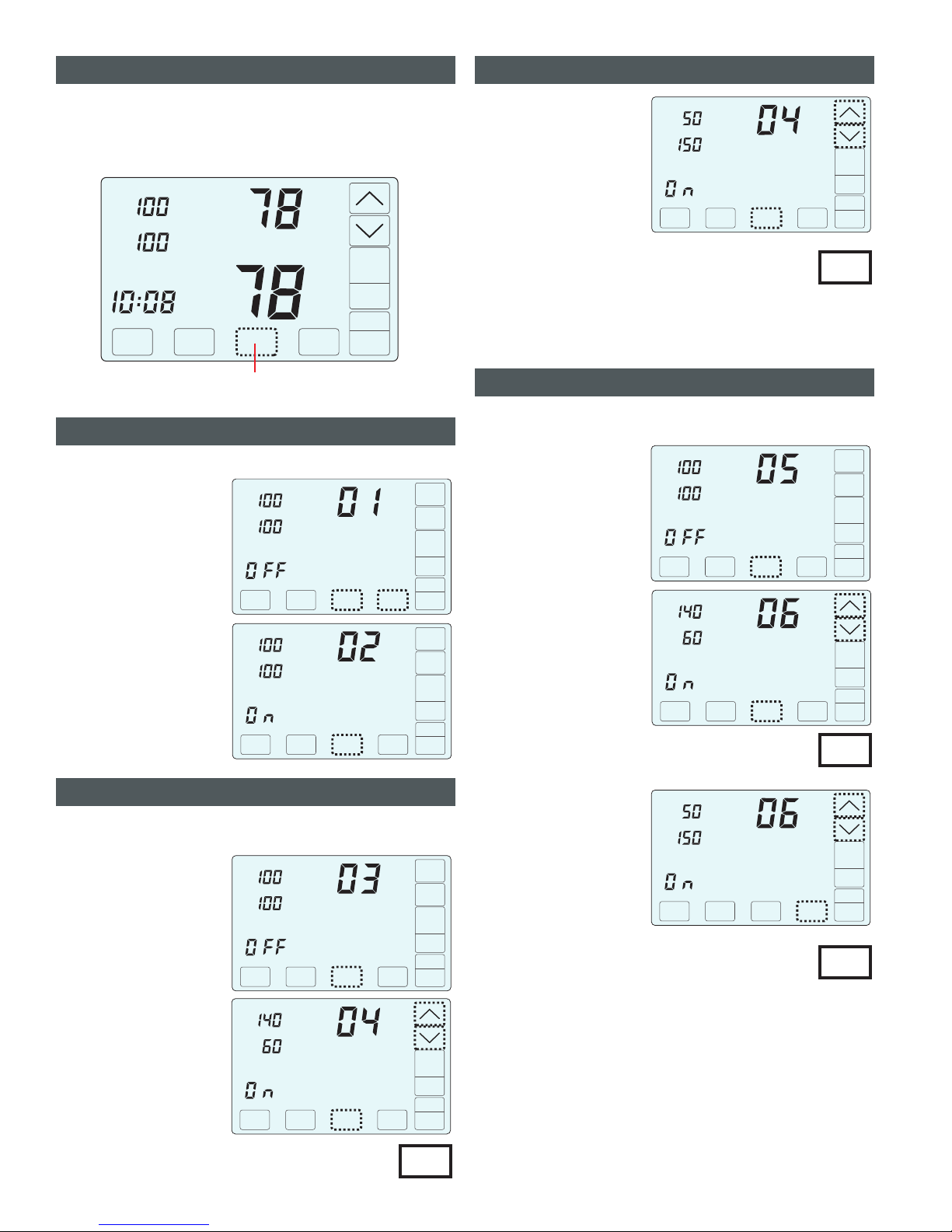
ACCESSING THE TEST MENU
To access the Test Menu, and the hidden Next key for 7
seconds until the fan test screen (Option 01) appears.
TOUCH HOLD
The Test Menu is used to test the Indoor Fan Operation, Allowable
Heating Airflow Limits and Allowable Cooling Airflow Limits.
Inside
Tu
Day
Upstairs
Auto
Downstairs
Airflow %
COOL
Schedule
AUTO
FANMENU MODE
Cool
Set To
SYSTEM
AM
TOUCH HOLD and this key for 7 seconds
to access the Installer Options.
01-02 Testing Indoor Fan Operation
In Option 1, the Fan is Off.
Touch to go to Option 2
to turn on the indoor fan. Verify
the fan is operating and
delivering airflow to the
upstairs and downstairs..
Touch to go Testing
Heating Airflow Limits.
NEXT
NEXT
Upstairs
Downstairs
Airflow % Test
FANNEXT ENTER
Upstairs
Downstairs
Airflow % Test
FANNEXT ENTER
03-04 Testing Heating Airflow Limits
In Option 3, the system is Off.
Touch to go to Option 4
to activate heating. Verify the
equipment is operating.
To determine the maximum
allowable upstairs airflow,
touch the key until the
airflow is too great and causes
noise or annoyance. Lower the
airflow using the key
until it is acceptable. This is the
maximum allowable upstairs
airflow in heating. Record the
airflow value.
NEXT
UP
DOWN
Upstairs
Downstairs
Airflow % Test
NEXT ENTER
Heat
Upstairs
Downstairs
Airflow %
NEXT ENTER
Heat
This test is used to verify that the indoor fan is operating correctly.
This test is used to determine the maximum allowable upstairs airflow
and the maximum allowable downstairs airflow in HEATING.
Maximum Allowable Upstairs Airflow in Heating
Upstairs
Downstairs
Airflow %
NEXT ENTER
Heat
To determine the maximum
allowable downstairs airflow,
touch the key until the
airflow is too great and causes
noise or annoyance. Increase
the airflow using the key
until it is acceptable. This is the
maximum allowable downstairs
airflow in heating. Record the
airflow value.
DOWN
UP
Maximum Allowable Downstairs Airflow in Heating
05-06 Testing Cooling Airflow Limits
In Option 5, the system is Off.
Touch to go to Option 6
to activate cooling. Verify the
equipment is operating.
To determine the maximum
allowable upstairs airflow,
touch the key until the
airflow is too great and causes
noise or annoyance. Lower the
airflow using the key
until it is acceptable. This is the
maximum allowable upstairs
airflow in cooling. Record the
airflow value.
NEXT
UP
DOWN
This test is used to determine the maximum allowable upstairs airflow
and maximum allowable downstairs airflow in COOLING.
Touch to go to Testing Cooling Airflow Limits.NEXT
Upstairs
Downstairs
Airflow %
NEXT ENTER
Cool
Upstairs
Downstairs
Airflow %
ENTER
Cool
Maximum Allowable Upstairs Airflow in Cooling
To determine the maximum
allowable downstairs airflow,
touch the key until the
airflow is too great and causes
noise or annoyance. Increase
the airflow using the key
until it is acceptable. This is the
maximum allowable downstairs
airflow in cooling. Record the
airflow value.
DOWN
UP
Maximum Allowable Downstairs Airflow in cooling
Touch to end testing and return to normal thermostat
operation.
ENTER
Upstairs
Downstairs
Airflow %
ENTER
Cool
Enter the maximum airflow limits using Options 17
through 20 of the installer menu.
03-04 Testing Heating Airflow Limits (cont.)
Test
Test
Test
Test
NEXT
Test
NEXT
Table of contents
Other eControls Thermostat manuals

eControls
eControls Comfort365 C365C32 User guide

eControls
eControls Comfort365 C365T21WF User manual

eControls
eControls Comfort365 C365T21 Operation and installation manual

eControls
eControls Comfort365 C365T11 User manual

eControls
eControls Comfort365 C365T21WF Operation and installation manual

eControls
eControls Comfort365 C365T21WF User manual

eControls
eControls C365T21WF Operation and installation manual

eControls
eControls Comfort365 C365T11 Operation and installation manual

eControls
eControls Comfort365 C365C32 User guide

eControls
eControls C365T21 Operation and installation manual


