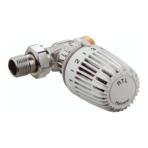
Heimeier Mikrotherm User manual

Pressurisation & Water Quality Balancing & Control Thermostatic Control ENGINEERING ADVANTAGE
Mikrotherm
Manual radiator valves with presetting

MANUAL RADIATOR VALVES - MIKROTHERM
2
Technical description
HEIMEIER Mikrotherm manual radiator valves made of corrosion-resistant gunmetal,
with white plastic hand wheel cap, tight-packed with protection film.
Lengths according to DIN 3841 part 1. Accurate presetting of the mass flow and finest heat
apportioning through a non-rising double spindle with a Mikrotherm presetting cone with
tandem sealing (metal and O-ring sealing). Spindle for DN 10 to DN 25 with double O-ring
sealing. Spindle sealing for DN 32 through stuffing box packaging which can be tightened.
Can be retrofitted as a thermostatic valve by replacing the Mikrotherm insert with a
thermostatic insert. Can be connected to a threaded pipe, or with compression fittings to a
copper, precision steel or multi-layer pipe. For HEIMEIER Mikrotherm, only use the auxiliary,
labelled HEIMEIER compression fittings (label e. g. 15 THE).
Permitted operating temperature TB 120°C (248°F). Permitted operating pressure
PB 10 bar, low pressure steam 110°C (230°F)/ 0.5 bar.
Assembly
Mikrotherm
Application
The HEIMEIER Mikrotherm manual radiator valve is used in warm water pump heating systems, gravity or low pressure steam
systems. With models in angle and straight form from DN 10 to DN 32, the manual radiator valve can be used for a number
of different purposes. The non-rising double spindle with the Mikrotherm presetting cone makes hydraulic balancing through
presetting possible. The aim here is to provide e. g. all heat consumers with hot water according to their needs.
Sample application
1. Double O-ring sealing
2. Double spindle
3. Tandem sealing
4. Presetting cone
• Body made of corrosion-resistant gunmetal nickel plated
• Double O-ring sealing (DN 10 – DN 25)
• Presetting through a non-rising double spindle
• Can be retrotted as a thermostatic valve
1. Mikrotherm

MANUAL RADIATOR VALVES - MIKROTHERM
3
Note
The contents of the heat transfer medium should comply with VDI guideline 2035 on damage and scale deposit formation in
warm water heating systems.
For industrial and long-distance energy systems, see the applicable codes VdTÜV 1466 and AGFW FW 510. Mineral oils in the
heat transfer medium or lubricants containing mineral oils of any type lead to strong swelling and in most cases cause EPDM
seals to fail.
When using nitrite-free frost and corrosion resistance solutions with an ethylene glycol base, pay close attention to the details
outlined in the manufacturers‘ documentation, particularly details concerning concentration and specific additives.
Operation
Presetting
1. Close the valve.
2. Unscrew the hand wheel fastening screw.
3. Screw in the control pin with a screw driver by turning it clockwise until it stops.
4. Use the diagrams to determine the presetting and preset by turning to the left.
5. Insert the hand wheel fastening screw and screw tight.
Notes:
– The insert should only be loosened or tightened when the valve is opened.
– After the first test heating with DN 32, check the stuffing box union nut and tighten if necessary.
Articles
Angle
DN kvs Article No
10 (3/8”) 1,71 0121-01.500
15 (1/2”) 1,99 0121-02.500
20 (3/4”) 3,30 0121-03.500
25 (1”) 6,60 0121-04.500
32 (1 1/4”) 10,10 0121-05.500
Straight
DN kvs Article No
10 (3/8”) 1,17 0122-01.500
15 (1/2”) 1,61 0122-02.500
20 (3/4”) 3,10 0122-03.500
25 (1”) 6,20 0122-04.500
32 (1 1/4”) 8,90 0122-05.500

MANUAL RADIATOR VALVES - MIKROTHERM
4
Accessories
Compression tting
for copper or precision steel pipes.
Metal-to-metal joint. Brass nickel-plated.
Female thread connection Rp 3/8 –
Rp 3/4. Support sleeves should be used
for a pipe wall thickness of 0.8 – 1 mm.
Follow the specifications of the pipe
manufacturer.
Ø Pipe DN Article No
12 10 (3/8”) 2201-12.351
15 15 (1/2”) 2201-15.351
16 15 (1/2”) 2201-16.351
18 20 (3/4”) 2201-18.351
22 20 (3/4”) 2201-22.351
Support sleeve
for copper or precision steel pipe with a
1 mm wall thickness. Brass.
LØ Pipe Article No
25,0 12 1300-12.170
26,0 15 1300-15.170
26,3 16 1300-16.170
26,8 18 1300-18.170
Compression tting
For multi-layer pipes.
Female thread connection Rp 1/2.
Nickel-plated brass.
Ø Pipe Article No
16 x 2 1335-16.351
Thermostatic insert
Conversion insert for valve bodies with
a «T label». Series to 1985.
DN Article No
10, 15 (3/8”, 1/2”) 4101-02.300
20 (3/4”) 4101-03.300
25 (1”) 2001-04.299
32 (1 1/4”) 2001-05.299
Thermostatic insert
Conversion insert for valve bodies with
a connector thread for the thermostatic
head. Series from 1985.
DN Article No
10, 15 (3/8”, 1/2”) 1302-02.300
20 (3/4”) 2001-03.300
Thermostatic insert
Standard. Conversion insert for valve
bodies with a boss marking. Series from
1994.
DN Article No
10, 15 (3/8”, 1/2”) 2001-02.300
Thermostatic insert
Presetting (V-exakt). Conversion insert
for valve bodies with a boss marking.
Brass numerical cap.
Series from 1994.
DN Article No
10, 15 (3/8”, 1/2”) 3501-02.300
Thermostatic insert
Finest presetting (F-exakt). Conversion
insert for valve bodies with a boss mar-
king. Nickel-plated brass numerical cap.
Series from 1994.
DN Article No
10, 15 (3/8”, 1/2”) 3420-02.300

MANUAL RADIATOR VALVES - MIKROTHERM
5
Technical data
Diagram DN 10 (3/8“)
Angle / Straight
0121-01 / 0122-01
Diagram DN 15 (1/2“)
Angle / Straight
0121-02 / 0122-02
60
50
30
20
10
5
3
2
1
0,1
0,2
0,3
0,5
35 10 20 30 50 100 200 300 500 1000 2000
ª “
600
500
300
200
100
50
30
20
10
1
2
3
5
6000
5000
3000
2000
1000
500
300
200
100
10
20
30
50
∆
p[kPa]
∆
p[mbar]
¥ /æ
230
∆
p[mm WS]
0,056 0,1
0,14
0,18 0,35 0,65 1
DM
æ 1,17 1,45
EM
æ 1,71
234567899
10
*)
60
50
30
20
10
5
3
2
1
0,1
0,2
0,3
0,5
35 10 20 30 50 100 200 300 500 1000 2000
ª “
600
500
300
200
100
50
30
20
10
1
2
3
5
6000
5000
3000
2000
1000
500
300
200
100
10
20
30
50
∆
p[kPa]
∆
p[mbar]
¥ /æ
230
∆
p[mm WS]
0,056 0,1
0,14
0,21 0,4 0,74
1,13 DM
æ 1,61
1,75
EM
æ 1,99
23456789
910
*)
*) Screwdriver rotations

MANUAL RADIATOR VALVES - MIKROTHERM
6
Diagram DN 20 (3/4“)
Angle / Straight
0121-03 / 0122-03
Diagram DN 25 (1“)
Angle / Straight
0121-04 / 0122-04
60
50
30
20
10
5
3
2
1
0,1
0,2
0,3
0,5
35 10 20 30 50 100 200 300 500 1000 2000
ª “
600
500
300
200
100
50
30
20
10
1
2
3
5
6000
5000
3000
2000
1000
500
300
200
100
10
20
30
50
∆
p[kPa]
∆
p[mbar]
¥ /æ
230
∆
p[mm WS]
0,064 0,11
0,15 0,32
0,54 1,12 1,98
DM
æ 3,1
2,5
EM
æ 3,3
23456789
10
10
*)
10 20 30 50 100 200 300 500
1000 2000
ª “
30
0,46 0,77 1,27 2,3 3,4
4,4
5,3
DM
æ 6,2
5,8
EM
æ 6,6
2
¥ /æ
60
50
30
20
10
5
3
2
1
0,1
0,2
0,3
0,5
∆
p[kPa]
3000 5000
50
30
3456789
12
12
600
500
300
200
100
20
10
1
2
3
5
6000
5000
3000
2000
1000
500
300
200
100
10
20
30
50
∆
p[mbar]
∆
p[mm WS]
*)
*) Screwdriver rotations

MANUAL RADIATOR VALVES - MIKROTHERM
7
Diagram DN 32 (11/4“)
Angle / Straight
0121-05 / 0122-05
*) Screwdriver rotations
Sample calculation
Target: Preset value
Given: Heat flow º= 2210 W
Temperature spread t = 20 K (70/50°C)
Pressure loss in manual valve DN 15 pv = 30 mbar
Solution: Mass flow ª= º/ (c · t) = 2210 / (1,163 · 20) = 95 kg/h
Screw driver turns from
diagram DN 15 = 6.5 turns
10 20 30 50 100 200 300 500
1000 2000
ª “
30
0,57
0,79
1,42 2,2 3,8
5,3
DM
æ 8,9
6,6 EM
æ 10,1
2
¥ /æ
60
50
30
20
10
5
3
2
1
0,1
0,2
0,3
0,5
∆
p[kPa]
3000 5000
50
30
345678
10
12
12
7,9
600
500
300
200
100
20
10
1
2
3
5
6000
5000
3000
2000
1000
500
300
200
100
10
20
30
50
∆
p[mm WS]
∆
p[mbar]
*)
cv= kv
0,86
kv= cv· 0,86

MANUAL RADIATOR VALVES - MIKROTHERM
Dimensions
Lengths according to DIN 3841, part 1
Angle form Straight form
Spanner opening
DN D b d1d2l1l2l3l4l5l6SW1SW2H1D1
10 Rp3/8 10,1 G5/8 R3/8 59 85 26 52 22 6 22 27 56 42
15 Rp1/2 13,2 G3/4 R1/2 66 95 29 58 26 7 27 30 56 42
20 Rp3/4 14,5 G1 R3/4 74 106 34 66 29 8 32 37 58 42
25 Rp1 13 G1 1/4 R1 84 118 40 75 30,5 9 41 47 73 55
32 Rp 1 1/4 15 G1 1/2 R1 1/4 95 135 46 85 39 10 49 52 74 55
α= 70° (±10°)
Ø D
1
l
6
d
2
d
1
α
l
3
l
4
D
b
H
1
l
5
SW
2
SW
1
d2
d1
α
l1
l2
SW2
b
H1
D
SW1
Ø D1
l6
The products, texts, photographs, graphics and diagrams in this document may be subject to alteration by TA Hydronics
without prior notice or reasons being given.
For the most up to date information about our products and specifications, please visit www.tahydronics.com.
4100-18.483 03.2011
partner in your country
www.tahydronics.com
Table of contents
Other Heimeier Control Unit manuals
Popular Control Unit manuals by other brands

Sun Oracle
Sun Oracle Sun Blade X6275 M2 installation guide

AUROOM
AUROOM DICIA D Installation and operation manual

Watts
Watts Ames 986GD Installation, operation and maintenance manual

SEW-Eurodrive
SEW-Eurodrive BMV operating instructions

Parallax
Parallax 28560 manual
Automated Logic
Automated Logic UNI/59 Technical instructions
